ESPAÑOL Aplacadora manual AG98F 4 ENGLISH AG98F
Anuncio
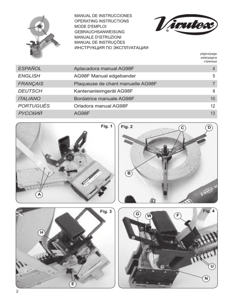
MANUAL DE INSTRUCCIONES OPERATING INSTRUCTIONS MODE D'EMPLOI GEBRAUCHSANWEISUNG MANUALE D'ISTRUZIONI MANUAL DE INSTRUÇÕES ИНСТРУКЦИЯ ПО ЭКСПЛУАТАЦИИ página/page seite/pagina страница ESPAÑOL Aplacadora manual AG98F 4 ENGLISH AG98F Manual edgebander 5 FRANÇAIS Plaqueuse de chant manuelle AG98F 7 DEUTSCH Kantenanleimgerät AG98F 8 ITALIANO Bordatrice manuale AG98F 10 PORTUGUÉS Orladora manual AG98F 12 РУССКИЙ AG98F 13 Fig. 1 Fig. 2 C D B A Fig. 3 G Fig. 4 W F H U N E 2 LADO FIJO G L P J K I Fig. 5 LADO MÓVIL Fig. 6 Fig. 7 Fig. 8 M R Q S Fig. 9 T Fig. 10 3 TE". (Fig. 5). 6. ENCOLADO DE CANTOS 1. Situar el aparato al principio del tablero, asegurándose que la cinta preencolada sobrepasa al menos 1 cm del extremo del mismo; (Fig. 6). 2. Pulsar el interruptor a la posición I ó II para la puesta en marcha del calefactor y esperar unos segundos hasta que alcance la temperatura de régimen y la cola del canto empiece a fundir. 3. Presionar la cinta preencolada contra el tablero, actuando sobre el pomo M, (Fig. 7), y desplazar la máquina a lo largo del mismo; (Fig. 6 y 7). 4. Accione la tijera al llegar el prensor al final del tablero con lo que la cinta quedará cortada, con un sobrante de 2 cm por este lado y continúe el encolado hasta su terminación. (Fig. 8). NOTA. - El calefactor del aparato dispone de dos temperaturas de salida (posiciones I y II del interruptor), 300°C. Y 525°C. Deberá emplear una u otra según la velocidad de avance con que encole Vd. y la calidad de la cola de la cinta preencolada que use. 7. MANTENIMIENTO Desconectar la máquina de la red eléctrica, antes de efectuar cualquier operación de mantenimiento. Cambio de cuchillas: Retirar el tornillo N, (Fig. 4), que sujeta el cuerpo portacuchillas sobre el rodillo encolador y dándole la vuelta a la máquina, soltar los tres tornillos P, (Fig. 6), que lo mantienen solidario con el lado fijo. Separar el cuerpo portacuchillas de la máquina; (Fig. 9). Retirar el canalizador de cinta Q, (Fig. 9), el deflector R y la cuchilla trasera S, (Fig. 10). En la parte superior del cuerpo portacuchillas aparecen las cabezas de los tornillos T, (Fig. 9) que sujetan la cuchilla delantera. Aflojar y retirar dichos tornillos con lo que la cuchilla delantera quedará suelta. Proceder al cambio de cuchillas, y el armado del conjunto de portacuchillas, en el orden inverso al seguido para desmontarlo. 8. ACCESORIOS OPCIONALES 5246025- Rodillo inclinado a 4°: pensado para aplacar cantos sobre planos inclinados de puertas, etc. 9. NIVEL DE RUIDO Y VIBRACIONES Los niveles de ruido y vibraciones de esta herramienta han sido medidos de acuerdo con la Norma Europea EN50144. El nivel de ruidos en el puesto de trabajo puede sobrepasar 85dB(A). En este caso es necesario tomar medidas de protección contra el ruido para el usuario de la herramienta. 10. GARANTIA Todas las máquinas electroportátiles VIRUTEX tienen una garantía válida de 12 meses a partir del día de su suministro, quedando excluidas todas las manipulaciones o daños ocasionados por manejos inadecuados o por desgaste natural de la máquina. Para cualquier reparación dirigirse al servicio oficial de asistencia técnica VIRUTEX. VIRUTEX se reserva el derecho de modificar sus productos sin previo aviso. English AG98F MANUAL EDGEBANDER IMPORTANT CAUTION. Read these OPERATING INSTRUCTIONS and the attached GENERAL SAFETY INSTRUCTIONS LEAFLET carefully before using the machine. Make sure you have understood them before operating the machine for the first time. Keep both sets of instructions for any future queries. WARNING! Before using the machine carefully read the GENERAL SAFETY INSTRUCTION LEAFLET enclosed with the machine documents. WARNING! This tool works at 525°C.=1000°F., without a flame or any visual indication. Precautions must be taken against the slight burning risk. • Cereless use of this device can cause fire. • Pay close attention when using the device in places where combustible materials are to be found. Do not use it in the same place over a long period of time. • Do not use the device in an atmosphere where an explosion could take place. • Heat can be transmitted to combustible materials located outside one's visual field. • After use, place the device on its holder and let it cool before putting it back in place. • Do not leave this device unattended when not in use. • If the feeding cable is damaged, have it replaced by the manufacturer, technical service or other qualified person in order to prevent possible hazards. 1. SPECIFICATIONS Input Power.................................................1.500 W Equivalent measured continuous acoustic pressure level A..........................65,6 dB(A) Normal level of vibrations (hand-arm)..........<2,5m/s2 Temperatures..................................I - 300°C=570°F ...................................................II - 525°C=1.000°F Approximate flow-rate................................400l/min Max. banding width.......50 mm with thickness of 1 mm Max. banding width........30 mm with thickness of 2 mm Weight...........................................................2,7 Kg 5 2. INSTRUCTIONS LOADER 1. Assembly: Fit the loader in its housing, by means of screws A, (Fig.1). 2. Adjustment: A) Loosen Knob B, (Fig. 2), and remove the cover from the loader. B) Adjust the Three rods C to the internal diameter of the strip roll. C) Place the pre-glued strip roll in the support, return the cover to the loader D and rescue it by means of knob B. 3. PASSING THROUGH OF STRIP 1. Loosen knobs E, (Fig. 3), and separate the two bodies so as to allow the strip to pass. 2. Pass the strip under the non-return rod F, (Fig. 4), and through knives U until it is under glueing roller W. 3. Close the moving body G by means of knob H, (Fig. 3), to the width of the strip, without clamping it so that it is guided, and secure it in this position with knobs E, (Fig. 3). 4. CLAMPS Carry out the adjustments in the order given bellow: 1. Fixed side: A) With an overlap: If you wish a 1,5 mm overlap on this side, place clamp I, (Fig. 5), at the end of the slotted lever (position furthest away from the fixed body), and lock it in this position with knob J. B) Flush with the board: If you wish to glue the edge on this side, flush with the board, place clamp I at the end of the fixed body and lock it in this position with knob J. 2. Moving side: Loosen knob K, (Fig. 5), open clamp G. Place the panel between the two clamps, bring clamp G up, until clamping the panel with knob K. Then remove the panel; close the moving clamp G 2 mm more, taking scaled plate L as a reference, and lock the clamp G in this position with knob K. In this way, the pressure of the leaf springs is adjusted, and the machine is ready to work. 5. OVERLAP DISTRIBUTION The overlap, or the difference in widths between the panel that we are going to edge and the width of the strip we are using, is distributed as follows: 1. Fixed side: The overlap on this side will be 1,5 mm, or there will be no overlap, depending on the way we have adjusted the clamp I (see clamps section) (Fig. 5). 2. Moving side: A) All the overlap will remain on this side of the panel, if the fixed side clamp I has been adjusted "FLUSH WITH THE BOARD". (Fig. 5). B) If the fixed side clamp I has been adjusted with an overlap of 1,5 mm, all the overlap excepting 1,5 mm will remain on this side of the panel; (Fig. 5). 6 6. EDGE BANDING 1. Place the tool at the beginning of the panel, making sure that the pre-glued strip exceeds the panel end by at least 1 cm: (Fig. 6). 2. Press the switch to position I or II to start up the heater and wait for a few seconds until the rated temperature is reached and the strip glue starts to melt. 3. Press the pre-glued strip against the panel, by pushing on knob M, (Fig. 7), and displace the machine along the panel; (Figs. 6 and 7). 4. Operate the cutting lever, when the clamps reaches the end of the panel, and continue edging until the panel end; (Fig. 8). NOTE. - The heater has two output temperatures (switch positions I and II): 300°C and 525°C (570°F. and 1000°F). One or the other is to be used in relation to the advance speed at which you are edging and the quality of the glued on the pre-glued strip you are using. 7. MAINTENANCE Before performing any maintenance operation, disconnect machine from power source. Changing knives: Remove screw N, (Fig. 4), which secures the knifeholding body on the glueing roller and, turning the machine over, loosen the three screws P, (Fig. 6), joining it to the fixed body. Separate the knife-holding body from the machine; (Fig.9). Remove the strip guide Q, (Fig. 9), deflector R and rear knife S, (Fig. 10). The heads of screws T, (Fig. 9) securing the front knife appear in the upper part of the knife-holding body. Loosen and remove these screws, and the front knife will thus be released. Change the knives, and assemble the knife-holding unit in the opposite order to that given for dismantling it. 8. OPTIONAL ACCESSORIES 5246025- Inclined roller (4°), for door edges,.... 9. NOISE AND VIBRATION LEVEL The noise and vibration levels of this electrical device have been measured according to the European standard EN50144. The noise level in the workplace can exceed 85dB(A), in which case it is necessary for the user to take noise protection measures. 10. WARRANTY All VIRUTEX power tools are guaranteed for 12 months from the date of purchase, excluding any damage which is a result of incorrect use or fo natural wear and tear on the machine. All repairs should be carried out by the official VIRUTEX technical assistance service. VIRUTEX reserves the right to modify its products without prior notice.

