manual
Anuncio
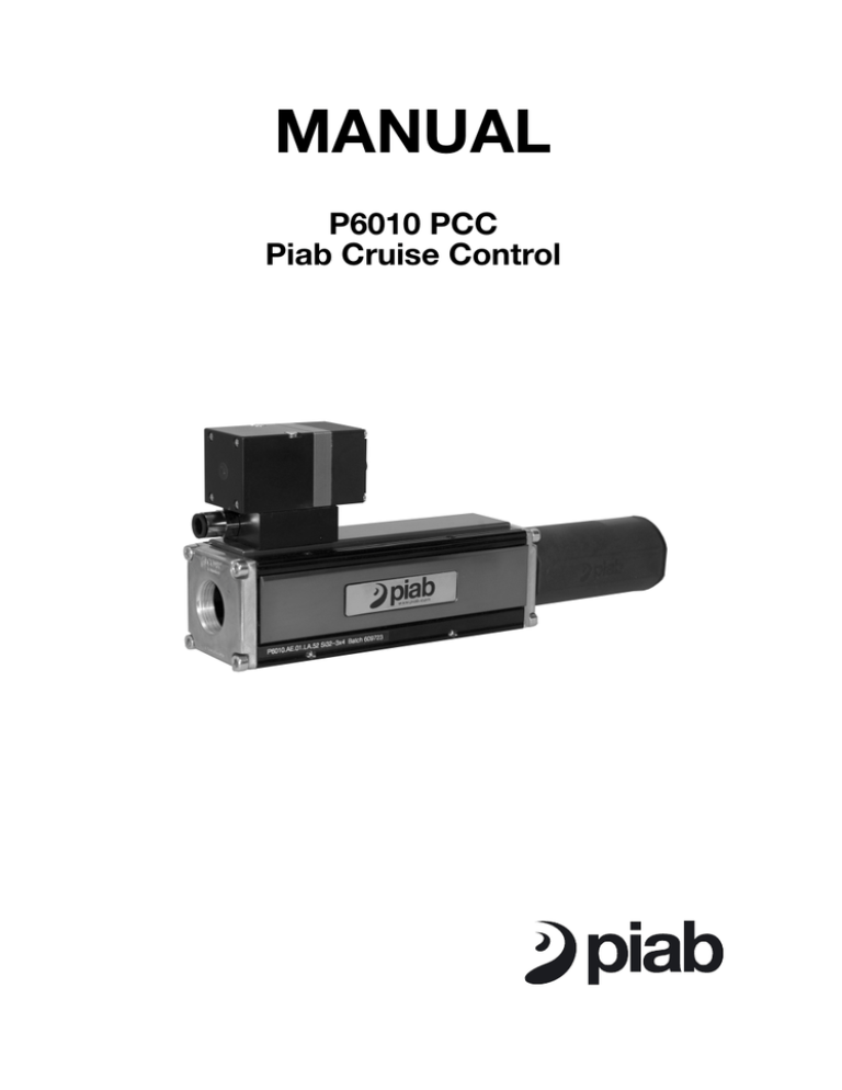
MANUAL P6010 PCC Piab Cruise Control English P6010 PCC Piab Cruise Control FUNCTION P6010 PCC is used in applications where a constant vacuum pressure is desired. When the P6010 PCC starts up, it works with maximum efficiency until the requested vacuum level is reached and then the feed pressure is controlled by P6010 PCC so that the operating vacuum level in the pump is kept constant. The analogue voltage, setpoint value, corresponds to the operation pressure. The regulator senses the actual operation pressure, actual value, that is required for the application, and the feed pressure of the compressed air to the Piab pump is controlled accordingly. The operation pressure is thus kept constant in this manner. In order to control ON/OFF of the pump, the analogue control voltage has to be set to zero. Note: If the power supply, 24VDC, to the PCC is turned off, P6010 PCC will shut off. . 2 1 1. Vacuum pump P6010 (see separate manual) 2. PCC module Constant vacuum E P 1 3 2 2 English P6010 PCC Piab Cruise Control INTERNAL CONNECTIONS The PCC is built in a “closed loop”, which means that the microprocessor compares the actual operation pressure (actual value) with the set operation pressure (setpoint). Setpoint Microprocessor Actual value Solenoid valve Pressure chamber Pressure converter Outlet pressure Pump Setpoint, 0–10V Power Supply GND Microprocessor Regulator exhaust In Sensing Out 3 English P6010 PCC Piab Cruise Control INSTALLATION P6010 PCC can be mounted in any desired angle. Make sure that the deaeration port is not blocked. If blocked, it will deteriorate the function of the PCC. The design of the PCC requires that the incoming pressure is 0.2 MPa [29 psi] higher than the output pressure. Valid for max flow, lower flows require lower differences. Note: The quality of the compressed air must meet the DIN ISO 8573-1 class 4 requirements. Check that correct hose dimensions are used, so that no pressure drops are caused. Avoid using long hoses, angled couplings and sharp bends. DIN ISO 8573-1 Class 1 2 3 4 5 6 7 Particle size max. in μm Particle density max. in mg/ m³ 0.1 1 5 15 40 — — 0.1 1 5 8 10 — — Water Water Oil Pressure dew point in °C Water g/m³ Residual oil content in mg/m³ -70 0.003 -40 0.117 -20 0.88 3 5.95 7 7.73 10 9.36 Cannot be specified. 0.01 0.1 1 5 25 — — The P6010 PCC should always be connected to a stabilized 24 V power supply and an external control voltage (setpoint). The unit is controlled either by an external control unit (a PLC, for example) or by a simple potentiometer. The controlling unit must be able to supply a 0–10 V signal for the setpoint value. If a potentiometer is used for control, it should be connected according to the schematics. The position of the potentiometer sets the setpoint value. 4 English P6010 PCC Piab Cruise Control 24V Power supply > 120 mA - + PLC P6010 PCC Pin 1 Pin 2 Pin 3 Pin 4 Pin 5 0-10V Setpoint value Signal ground +24 VDC Power supply 0-10V Setpoint value GND Supply / Signal Analog out 0-10V Not used 24V Power supply > 100 mA - + P6010 PCC 0-10V Setpoint value Potentiometer Pin 1 Pin 2 Pin 3 Pin 4 Pin 5 +24 VDC Power supply 0-10V Setpoint value GND Supply / Signal Analog out 0-10V Not used 5 English P6010 PCC Piab Cruise Control PNEUMATIC CONNECTIONS A B 1 2 1 Compressed air, inlet 2 Vacuum 3 Exhaust A Power supply/Signal B Regulator exhaust port, PCC 6 3 English P6010 PCC Piab Cruise Control ELECTRICAL CONNECTION 2 3 1 5 4 2 3 1 5 4 A Detail A Pin No. Description 1 2 3 4 5 +24VDC Power supply 0-10V Setpoint value GND Supply / Signal Analog out 0-10V Not used DIMENSIONAL DRAWING E 4x M5 P 1 G1" 3 25 0.984" 2 77 3.03" 170 6.69" 214 8.43" 10.5 0.413" 117 4.61" 5-pin male, M12 G1/4" M5 73 2.87" 5.5 0.217" 7.5 0.295" 11 0.433" 142.5 5.61" 22 0.866" 1 1/4"NPSF, G1/4" 1"NPSF, G1" 2 1"NPSF, G1" 18.5 0.728" 1/8"NPSF, G1/8" 1/8"NPSF, G1/8" 3 34 1.34" 82 3.23" 53 2.09" 7 English P6010 PCC Piab Cruise Control TECHNICAL DATA Description Feed pressure, max. Feed pressure, min. Outlet pressure Unit Value MPa [psi] MPa [psi] MPa [psi] 1.0 [14.5] 0.12 [17.4] 0.02–0.9 [2.9–130.5] Nominal flowrate at 0.6 MPa Nl/s [scfm] in, 0.1 MPa ΔP Air consumption, internal Nl/s [scfm] Particle size, max μm Noise level dBA Material Connection, vacuum/exhaust Connection, compressed air Connection, regulator exhaust Voltage, supply VDC Voltage, signal in VDC Safety classification Current consumption mA Electrical connection Pressure drop (ΔP) MPa [psi] Linearity %FS Hysteresis %FS Repeteability %FS Input impedance, signal in kΩ 18.3 [38.8] 0.04 [0.085] 20 50–70 Al, CuZn, PA, NBR, SS G1” / 1” NPSF G1/4” G1/8” 24 (21.8–26.4) 0–10 IP65 30 M12 5-pin male 0.1 [14.5] <1.5 <0.5 <0.5 55 TECHNICAL DATA, SPECIFIC Description Scale factor, signal in Regulator operating range, vacuum level 8 Unit Value 0–90 -kPa = 0–10VDC [0–27 -inHg = 0–10VDC] -kPa [-inHg] 0–90 [0–27] English P6010 PCC Piab Cruise Control SPARE PARTS AND ACCESSORIES Pos Description Spare part no. 1 2 3 4 5 6 7 8 Function PCC Vacuum cpl. Regulator PCC Vacuum O-ring 8x1.5 O-ring 8x1.5 O-ring 9.1x1.5 O-ring 2.1x1.2 O-ring 2x1.3 O-ring 12x1.5 Cable M12 4-pin female PUR, 5m 0120021 0125796 0121817 2 1 3 4 5 6 8 7 PRECAUTIONS Irresponsible use of compressed air may cause injuries. Compressed air should never be used for any other purpose than the intended purpose. Remember to always shut off the supply of compressed air when cleaning or carrying out maintenance on the modules. WARRANTY One year warranty. 9 Svenska P6010 PCC Piab Cruise Control FUNKTION P6010 PCC används i applikationer där en konstant vakuumnivå önskas. När P6010 PCC startar arbetar den med maximal effekt tills den önskade vakuumnivån nåtts. Drivtrycket styrs då av P6010 PCC så att vakuumnivån i pumpen hålls konstant. Den analoga spänningen, BÖR-värdet, motsvarar arbetstrycket. Regulatorn känner av det verkliga arbetstrycket, ÄR-värdet, som krävs för applikationen, och tryckluftens drivtryck till Piab-pumpen regleras därefter. Arbetstrycket hålls på så sätt konstant. För att styra pumpen TILL/FRÅN skall den analoga spänningen ställas in på noll (0). OBS! Om spänningen, 24 VDC, till PCC bryts, kommer P6010 PCC att stängas av. . 2 1. Vakuumpump P6010 (se separat manual) 1 2. PCC-modul Konstant vakuum E P 1 3 2 10 Svenska P6010 PCC Piab Cruise Control INTERNA ANSLUTNINGAR PCC är uppbyggd med "sluten slinga," vilket innebär att mikroprocessorn jämför det verkliga (ÄR) arbetstrycket med det inställda (BÖR) arbetstrycket. Referenssignal Mikroprocessor ÄR-värde Solenoidventil Tryckkammare Utloppstryck Tryckomvandlare Pump BÖR-värde, 0–10V Strömförsörjning Jord Mikroprocessor Avluftning In Avkänning Ut 11 Svenska P6010 PCC Piab Cruise Control INSTALLATION P6010 PCC kan monteras i vilken vinkel som helst. Se till att avluftningsporten inte är blockerad. Blockerad avluftning försämrar funktionen hos PCC. Konstruktionen av PCC kräver att inloppstrycket är 0,2 MPa högre än utloppstrycket. Gäller vid max. flöde. Lägre flöden kräver mindre skillnader. Notera: Tryckluftens kvalitet skall uppfylla DIN ISO 8573-1 klass 4. Kontrollera att rätt slangdimension används så att inga tryckfall uppstår. Undvik långa slangar, vinklade kopplingar och skarpa böjar. DIN ISO 8573-1 Klass Restpartiklar μm 1 2 3 4 5 6 7 0,1 1 5 15 40 — — Restpartiklar mg/m³ 0,1 1 5 8 10 — — Restvatten DTP°C Restvatten g/m³ -70 0,003 -40 0,117 -20 0,88 3 5,95 7 7,73 10 9,36 Kan inte specificeras. Resterande olja mg/m³ 0,01 0,1 1 5 25 — — P6010 PCC kopplas alltid in till en stabiliserad 24 V spänningskälla och en extern styrspänning (BÖR-värde). Styrning av enheten kan ske på två sätt; antingen via en yttre kontrollenhet (t. ex. en PLC) eller med en enkel potentiometer. Kontrollenheten måste klara att tillföra en 0-10 V signal för BÖR-värdet. Om styrningen sker via en potentiometer kopplas den in enligt schemat. Potentiometerns läge ställer in BÖR-värdet. 12 Svenska P6010 PCC Piab Cruise Control 24V strömförsörjning > 120 mA - + PLC P6010 PCC Pin 1 Pin 2 Pin 3 Pin 4 Pin 5 0-10V BÖR-värde Signaljord +24 VDC strömförsörjning 0-10V BÖR-värde Matnings- / signaljord Analog utgång 0-10V Används ej 24V strömförsörjning > 100 mA - + P6010 PCC 0-10V BÖR-värde Potentiometer Pin 1 Pin 2 Pin 3 Pin 4 Pin 5 +24 VDC strömförsörjning 0-10V BÖR-värde Matnings- / signaljord Analog utgång 0-10V Används ej 13 Svenska P6010 PCC Piab Cruise Control PNEUMATISKA ANSLUTNINGAR A B 1 2 1 Tryckluft, inlopp 2 Vakuum 3 Utblås A Strömförsörjning/Signal B Avluftningsport PCC 14 3 Svenska P6010 PCC Piab Cruise Control ELANSLUTNING 2 3 1 5 4 2 3 1 5 4 A Detalj A Pin nr. Beskrivning 1 2 3 4 5 +24VDC strömförsörjning 0-10V BÖR-värde Matnings- / signaljord Analog utgång 0-10V Används ej MÅTTSKISS E 4x M5 P 1 G1" 3 25 0.984" 2 77 3.03" 170 6.69" 214 8.43" 10.5 0.413" 117 4.61" 5-pin male, M12 G1/4" M5 73 2.87" 5.5 0.217" 7.5 0.295" 11 0.433" 142.5 5.61" 22 0.866" 1 1/4"NPSF, G1/4" 1"NPSF, G1" 2 1"NPSF, G1" 18.5 0.728" 1/8"NPSF, G1/8" 1/8"NPSF, G1/8" 3 34 1.34" 82 3.23" 53 2.09" 15 Svenska P6010 PCC Piab Cruise Control TEKNISKA DATA Beskrivning Drivtryck, max. Drivtryck, min. Utloppstryck Nominellt flöde vid 0.6 MPa in, 0.1 MPa ΔP Luftförbrukning, intern Partikelstorlek, max Ljudnivå Material Anslutning, vakuum/utblås Anslutning, tryckluft Anslutning, regulatorutblås Spänning, strömförsörjning Spänning, signal in Säkerhetsklass Strömförbrukning Elanslutning Tryckfall (ΔP) Linearitet Hysteres Repeternoggrannhet Ingångsimpedans, insignal Enhet Värde MPa MPa MPa Nl/s Nl/s μm dBA 1.0 0.12 0.02–0.9 18.3 0.04 20 50–70 Al, CuZn, PA, NBR, SS G1” / 1” NPSF G1/4” G1/8” 24 (21.8–26.4) 0–10 IP65 30 M12 5-pin hane 0.1 <1.5 <0.5 <0.5 55 VDC VDC mA MPa %FS %FS %FS kΩ TEKNISKA DATA, SPECIFIKA Beskrivning Skalfaktor, signal in Regulatorns arbetsområde, vakuumnivå 16 Enhet Värde -kPa 0–90 -kPa = 0–10 VDC 0–90 Svenska P6010 PCC Piab Cruise Control RESERVDELAR OCH TILLBEHÖR Pos Beskrivning Art. nr. 1 2 3 4 5 6 7 8 Funktion PCC Vakuum kpl. Regulator PCC Vakuum O-ring 8x1.5 O-ring 8x1.5 O-ring 9.1x1.5 O-ring 2.1x1.2 O-ring 2x1.3 O-ring 12x1.5 Kabel M12 4-pin hona, PUR, 5m 0120021 0125796 0121817 2 1 3 4 5 6 8 7 SÄKERHETSÅTGÄRDER Ansvarslöst användande av tryckluft kan orsaka personskador. Tryckluft får aldrig användas till något annat än det avsedda ändamålet. Kom ihåg att alltid stänga av tillförseln av tryckluft vid rengöring eller reparation av modulerna. GARANTI Ett års garanti. 17 Deutsch P6010 PCC Piab Cruise Control FUNKTION Die P6010 PCC wird eingesetzt, bei Anwendungen in denen ein konstantes Vakuum gewünscht wird. Wenn die P6010 PCC startet, arbeitet diese mit maximaler Leistung, bis das erforderliche Vakuumniveau erreicht ist. Dann wird der Speisedruck durch die P6010 PCC gesteuert, so dass das im Betrieb befindliche Vakuumniveau in der Pumpe konstant gehalten wird. Die analoge Spannung, Sollwert, entspricht dem benötigten Vakuum = Arbeitsvakuum. Der Regler erfasst das anstehende Arbeitsvakuum, das tatsächliche Vakuum, welches für die Anwendung erforderlich ist. Der Speisedruck zum betreiben der Piab Pumpe wird entsprechend gesteuert. Das Arbeitsvakuum wird auf diese Weise konstant gehalten. Zum EIN/AUS-Schalten der Pumpe, muss die analoge Steuerspannung auf Null gesetzt werden. Anmerkung: Bei Unterbrechung der Stromversorgung, 24 VDC, wird die Funktion der P6010 PCC komplett abgeschaltet. 2 1 1. Vakuumpumpe P6010 (siehe separates Handbuch) 2. Funktionsmodul PCC Konstantes Vakuum E P 1 3 2 18 Deutsch P6010 PCC Piab Cruise Control INTERNE ANSCHLÜSSE Die PCC ist als "geschlossener Kreis" konzipiert: d.h. der Mikroprozessor vergleicht den tatsächlichen (IST-Wert) mit dem eingestellten Betriebsdruck (SOLL-Wert). SOLL-Wert Mikroprozessor IST-Wert Magnetventil Druckkammer Druckumwandler Ausgangsdruck Pumpe SOLL-Wert, 0–10V Betriebsspannung Erde Mikroprozessor Entlüftung Eingang Eingang IST-Wert DruckAusgang 19 Deutsch P6010 PCC Piab Cruise Control INSTALLATION Der P6010 PCC lässt sich in jedem beliebigen Winkel montieren. Dabei darf der Entlüftungsport jedoch nicht blockiert sein, da sonst die Funktion des PCC beeinträchtigt wird. Konstruktionsbedingt muss der Vordruck 0,2 MPa höher als der Ausgangsdruck sein. Nur gültig für max. Volumenstrom, niedrigerer Volumenstrom benötigt eine geringere Druckdifferenz. Bitte beachten! Die Druckluftqualität muss entsprechen. DIN ISO 8573-1 Klasse 4 Bitte beachten Sie, dass der richtige Schlauchdurchmesser verwendet wird, damit kein Druckabfall entsteht. Lange Schläuche, gewinkelte Anschlüsse und scharfe Krümmungen sind zu vermeiden. DIN ISO 8573-1 Klasse Restpartikel μm 1 2 3 4 5 6 7 0,1 1 5 15 40 — — Restpartikel mg/m³ 0,1 1 5 8 10 — — Restwasser DTP°C Restwasser g/m³ -70 0,003 -40 0,117 -20 0,88 3 5,95 7 7,73 10 9,36 Lässt sich nicht spezifizieren. Restöl mg/m³ 0,01 0,1 1 5 25 — — Die P6010 PCC muss an eine stabilisierte Betriebsspannung sowie an einen externen SOLL-Wertgeber angeschlossen werden. Die Einheit wird entweder über eine externe Überwachung ( z.B. ein PLC ) oder ein Potentiometer gesteuert. Die Überwachungseinheit muss 0 - 10V Signale zur Bestimmung des SOLLWertes geben können. Potentiometer werden entsprechend nachstehenden Schemen angeschlossen. Die Einstellung des SOLL-Wertes geschieht über das Potentiometer. 20 Deutsch P6010 PCC Piab Cruise Control 24V Betriebsspannung > 120 mA - + PLC P6010 PCC Pin 1 Pin 2 Pin 3 Pin 4 Pin 5 0-10V Sollwert Erde, Signal +24 VDC-Betriebsspannung 0-10V Sollwert Erde Analoger Ausgang 0-10V nicht angeschlossen 24V Betriebsspannung > 100 mA - + P6010 PCC 0-10V Sollwert Potentiometer Pin 1 Pin 2 Pin 3 Pin 4 Pin 5 +24 VDC-Betriebsspannung 0-10V Sollwert Erde Analoger Ausgang 0-10V nicht angeschlossen 21 Deutsch P6010 PCC Piab Cruise Control ANSCHLÜSSE, PNEUMATISCH A B 1 2 1 Druckluft, Einlass 2 Vakuum 3 Abluft A Stromversorgung/Signal B Entlüftungsport PCC 22 3 Deutsch P6010 PCC Piab Cruise Control ELEKTRISCHE ANSCHLÜSSE 2 3 1 5 4 2 3 1 5 4 Detail A Pin Nr. Beschreibung 1 2 3 4 5 +24VDC Betriebsspannung 0-10V Sollwert Erde Analoger Ausgang 0-10V Nicht angeschlossen MAßSKIZZE E 4x M5 P 1 G1 3 25 0.984" 2 77 3.03" 170 6.69" 214 8.43" 10.5 0.413" 117 4.61" 5-pin male, M12 G1/4" M5 73 2.87" 5.5 0.217" 7.5 0.295" 11 0.433" 142.5 5.61" 22 0.866" 1 1/4"NPSF, G1/4" 1"NPSF, G1" 2 1"NPSF, G1" 18.5 0.728" 1/8"NPSF, G1/8" 1/8"NPSF, G1/8" 3 34 1.34" 82 3.23" 53 2.09" 23 Deutsch P6010 PCC Piab Cruise Control TECHNISCHE DATEN Beschreibung Betriebsdruck, max. Betriebsdruck, min. Druck, Ausgang Durchfluss, nomineller, bei 0,6 MPa am Eingang, 0.1 MPa ΔP Luftverbrauch, intern Partikelgröße max., Druckluft Geräuschpegel Material Anschluss, Vakuum Abluft Anschluss, Druckluft Anschluss, Entlüftung PCC Betriebsspannung Signalspannung, Eingang Schutzart Stromaufnahme Steckanschluss, elektrisch Druckunterschied (ΔP) Liniarität, vom Messbereich Hysterese, vom Messbereich Wiederholgenauigkeit, vom Messbereich Impedanz, Signaleingang Einheit Wert MPa MPa MPa Nl/s 1.0 0.12 0.02–0.9 18.3 Nl/s μm dBA 0.04 20 50–70 Al, CuZn, PA, NBR, SS G1” / 1” NPSF G1/4” G1/8” 24 (21.8–26.4) 0–10 IP65 30 M12 5-Pin Stecker 0.1 <1.5 <0.5 <0.5 55 VDC VDC mA MPa % % % kΩ TECHNISCHE DATEN, SPEZIFISCHE Beschreibung Vehältnisfaktor, Signaleingang PCC Arbeitsbereich, Vakuum 24 Einheit Wert -kPa 0–90 -kPa = 0–10VDC [0–27 -inHg = 0–10VDC] 0–90 [0–27] Deutsch P6010 PCC Piab Cruise Control ZUBEHÖR UND ERSATZTEILE Pos Beschreibung Ersatzteil-Nr. 1 2 3 4 5 6 7 8 Funktion PCC Vakuum kpl Reglulator PCC Vakuum O-Ring 8x1.5 O-Ring 8x1.5 O-Ring 9.1x1.5 O-Ring 2.1x1.2 O-Ring 2x1.3 O-Ring 12x1.5 Kabel M12 4-Pin Buchse PUR, 5m 0120021 0125796 0121817 2 1 3 4 5 6 8 7 SICHERHEITSMAßNAHMEN Ein verantwortungsloser Umgang mit Druckluft kann zu Personenschäden führen. Druckluft darf nur für den dafür bestimmten Zweck eingesetzt werden. Zur Reinigung oder Reparatur der Module ist die Druckluftzufuhr abzuschalten. GEWÄHRLEISTUNG 1 Jahr. 25 Français P6010 PCC Piab Cruise Control PRINCIPE DE FONCTIONNEMENT La P6010 PCC est préconisée pour les applications où un niveau de vide doit demeurer constant. Au démarrage, la P6010 PCC fonctionne à la puissance maximale jusqu'à atteindre le niveau de vide souhaité. La pression d'alimentation est ensuite ajustée automatiquement pour maintenir ce niveau de vide constant. Le signal d'entrée analogique, valeur de consigne, correspond au niveau de vide souhaité. Le régulateur mesure en permanence la dépression de service, valeur réelle effective, et la pression de l'alimentation en air comprimé de la pompe Piab est régulée en conséquence pour maintenir la dépression constante. La tension analogique doit être réglée à zéro pour commander le marche/ arrêt de la pompe. Note : En cas de coupure de l'alimentation 24Vdc du PCC, la P6010 PCC s'arrête. 2 1 1. Pompe à vide P6010 (voir manuel séparé) 2. Module de fonction PCC Vide constant E P 1 3 2 26 Français P6010 PCC Piab Cruise Control DIAGRAMME DE FONCTIONNEMENT Le PCC a une configuration en circuit fermé impliquant que le microprocesseur compare la pression de service réelle (VALEUR EFFECTIVE) avec la pression de service choisie (VALEUR DE CONSIGNE). Signal de référence Microprocesseur Valeur courante Electrovanne Chambre sous pression UPression de refoulement Convertisseur de pression Pompe Valeur de consigne, 0–10V Alimentation Terre Microprocesseur Purge d'air Entrée Détection Sortie 27 Français P6010 PCC Piab Cruise Control INSTALLATION La P6010 peut être installée dans toutes les positions. Il convient de veiller à ce que le port d'échappement du régulateur ne soit pas obstrué, ce qui détériorerait le PCC. La conception du PCC exige que la pression d'entrée soit supérieure de 0,2 MPa à la pression de sortie. Valable pour le débit max, des débits plus faibles nécessitent moins de différence. Note: La qualité de l'air comprimé doit satisfaire aux critères de la norme DIN ISO 8573-1 classe 4. Vérifiez que les diamètres des tuyaux utilisés soient correctement dimensionnés pour ne pas créer de pertes de charges. Evitez les tuyaux trop longs, les raccords coudés et les pincements. DIN ISO 8573-1 Classe Particules résiduelles μm Particules résiduelles mg/m³ Eau résiduelle Eau résiduelle Huile résiduelle DTP°C g/m³ mg/m³ 1 2 3 4 5 6 7 0,1 1 5 15 40 — — 0,1 1 5 8 10 — — -70 -40 -20 3 7 10 0,003 0,117 0,88 5,95 7,73 9,36 Non spécifiable. 0,01 0,1 1 5 25 — — La pompe P6010 PCC doit toujours être raccordée à une alimentation stabilisée 24Vcc et à une tension externe de commande (consigne). L'appareil peut aussi bien être piloté par une unité externe (un API par exemple), ou par un simple potentiomètre. L'unité externe doit simplement être en mesure de pouvoir fournir un signal 0-10V pour la valeur de consigne. Si un potentiomètre est utilisé pour la commande, veuillez respecter les schémas de raccordement ci-après. La position du potentiomètre fixe la valeur de consigne. 28 Français P6010 PCC Piab Cruise Control Alimentation 24V > 120 mA - + API P6010 PCC Borne 1 Borne 2 Borne 3 Borne 4 Borne 5 Point de consigne 0-10V Terre +24 Vdc Consigne 0-10V Terre Alimentation/Signal Sortie analogique 0-10V Non utilisée Alimentation 24V > 100 mA - + P6010 PCC Point de consigne 0-10V Potentiomètre Borne 1 Borne 2 Borne 3 Borne 4 Borne 5 +24 Vdc Consigne 0-10V Terre Alimentation/Signal Sortie analogique 0-10V Non utilisée 29 Français P6010 PCC Piab Cruise Control RACCORDEMENTS PNEUMATIQUES A B 1 2 1 Air comprimé, entrée 2 Aspiration 3 Echappement A Alimentation électrique / Signaux B Port d'échappement du régulateur PCC 30 3 Français P6010 PCC Piab Cruise Control RACCORDEMENTS ÉLECTRIQUES 2 3 1 5 4 2 3 1 5 4 A Détail A Borne n° Description 1 2 3 4 5 Alimentation +24Vdc Valeur de consigne 0-10V Terre Alimentation/Signaux Sortie analogique 0-10V Non utilisée DIMENSIONS E 4x M5 P 1 G 3 25 0.984" 2 77 3.03" 170 6.69" 214 8.43" 10.5 0.413" 117 4.61" 5-pin male, M12 G1/4" M5 73 2.87" 5.5 0.217" 7.5 0.295" 11 0.433" 142.5 5.61" 22 0.866" 1 1/4"NPSF, G1/4" 1"NPSF, G1" 2 1"NPSF, G1" 18.5 0.728" 1/8"NPSF, G1/8" 1/8"NPSF, G1/8" 3 34 1.34" 82 3.23" 53 2.09" 31 Français P6010 PCC Piab Cruise Control CARACTÉRISTIQUES TECHNIQUES Description Pression d'alimentation maxi. Pression d'alimentation mini. Pression de sortie Débit d'aspiration nominal à 0,6 MPa avec une ΔP de 0,1 MPa Consommation d'air, interne Taille des particules, max Niveau sonore Matériaux Raccordement, Aspiration & Echappement Raccordement, Air comprimé Raccordement, Échappement régulateur Tension d'alimentation Tension des signaux entrée/sortie Indice de protection Consommation électrique Raccordement électrique Perte de charge (ΔP) Linéarité Hystérésis Répétabilité Impédance d’entrée Unité Valeur MPa MPa MPa Nl/s 1,0 0,12 0,02–0,9 18,3 Nl/s μm dBA 0,04 20 50–70 Al, CuZn, PA, NBR,SS G1” / 1” NPSF G1/4” G1/8” 24 (21,8–26,4) 0–10 IP65 30 Connecteur mâle M12-5 bornes 0,1 <1,5 <0,5 <0,5 55 Vdc Vdc mA MPa %PE %PE %PE kΩ CARACTÉRISTIQUES TECHNIQUES, SPÉCIFIQUES Description Echelle des signaux d’entrée Etendue de régulation, vide 32 Unité Valeur -kPa 0–90 -kPa = 0–10Vdc 0–90 Français P6010 PCC Piab Cruise Control PIÈCES DÉTACHÉES ET ACCESSOIRES Pos Description Référence 1 2 3 4 5 6 7 8 Fonction PCC Vide, complet Régulateur PCC Vide Joint torique 8x1,5 Joint torique 8x1,5 Joint torique 9,1x1,5 Joint torique 2,1x1,2 Joint torique 2x1,3 Joint torique 12x1,5 Câble PUR 5m, M12 4 contacts 0120021 0125796 0121817 2 1 3 4 5 6 8 7 CONSIGNES DE SÉCURITÉ Une utilisation sans précaution de l'air comprimé peut provoquer de graves blessures. L'air comprimé ne doit jamais être utilisé à des fins autres que celles pour lesquelles elle est prévue. Veillez tout particulièrement à bien fermer l'alimentation de l'air comprimé avant toute intervention de maintenance ou de nettoyage sur les différents modules. GARANTIE 1 an. 33 Italiano P6010 PCC Piab Cruise Control FUNZIONAMENTO La P6010 PCC viene utilizzata in quelle applicazioni dove è richiesto un grado di vuoto costante. Avviando la pompa, questa si pone nella massima condizione di aspirazione fino al raggiungimento del grado di vuoto richiesto. La pressione di alimentazione viene quindi controllata dal dispositivo PCC, in modo da mantenere costante il livello di vuoto raggiunto. Alla tensione analogica in ingresso, valore di settaggio, corrisponde il valore di vuoto generato in uscita. Il sensore misura il grado di vuoto del sistema e mediante una valvola proporzionale viene regolata la pressione di alimentazione della pompa per raggiungere il grado di vuoto impostato. In questo modo il grado di vuoto viene mantenuto costante. Per il controllo ON/OFF della pompa, la tensione di alimentazione analogica deve essere regolata a zero. Nota: se la tensione di alimentazione di 24 VDC del PCC viene a mancare, la pompa verrà spenta. 2 1. Pompa a vuoto P6010 (vedi manuale specifico) 1 2. Modulo PCC Vuoto costante E P 1 3 2 34 Italiano P6010 PCC Piab Cruise Control STRUTTURA LOGICA Il PCC lavora in anello chiuso. Questo significa che l’uscita dipende dal confronto tra il valore attuale ed il valore impostato. Riferimento Microprocessore Elettrovalvola Pompa Lettura uscita Circuito Uscita Riferimento, 0–10V Alimentazione Terra Microprocessore Scarico regolatore In Lettura uscita Out 35 Italiano P6010 PCC Piab Cruise Control INSTALLAZIONE La P6010 PCC può essere installata con orientamento qualunque. Assicurarsi che lo scarico del regolatore sia libero. Diversamente, la funzionalità del PCC può essere compromessa. La struttura del PCC impone che la pressione di alimentazione sia superiore di almeno 0.2 MPa alla pressione di uscita. Valido per portata massima, portate inferiori richiedono differenze minori. Nota: L’aria compressa deve soddisfare la Norma DIN ISO 8573-1 classe 4. Le pompe dotate di PCC devono essere protette da filtri Piab, per evitare che la polvere possa intasare il sistema di controllo. Controllare il diametro delle tubazioni per non generare perdite di pressione. Evitare, inoltre, tubazioni lunghe, raccordi ad angolo e girevoli. DIN ISO 8573-1 Classe Polvere μm Polvere mg/m³ 1 2 3 4 5 6 7 0,1 1 5 15 40 — — 0,1 1 5 8 10 — — Acqua DTP°C Acqua g/m³ -70 0,003 -40 0,117 -20 0,88 3 5,95 7 7,73 10 9,36 Non specificata. Olio mg/m³ 0,01 0,1 1 5 25 — — La P6010 PCC deve sempre essere connessa ad una tensione di 24 V stabilizzata, nonchè, ad un sistema di controllo (per l’impostazione del riferimento). Tale sistema può essere un PC, un PLC o un semplice potenziometro, e deve essere in grado di gestire una tensione 0-10 V. Utilizzando un potenziometro la connessione deve essere effettuata secondo lo schema. La sua posizione imposta il valore di riferimento. 36 Italiano P6010 PCC Piab Cruise Control Tensione di alimentazione 24V > 120 mA - + PLC P6010 PCC Pin 1 +24 VDC Tensione di alimentazione Pin 2 0-10V Valore di settaggio Pin 3 Massa Pin 4 Uscita analogica 0-10V Pin 5 Non utilizzato 0-10V Valore di settaggio Massa Tensione di alimentazione 24V > 100 mA - + P6010 PCC 0-10V Valore selezionato Potenziometro Pin 1 +24 VDC Tensione di alimentazione Pin 2 0-10V Valore selezionato Pin 3 Massa Pin 4 Uscita analogica 0-10V Pin 5 Non utilizzato 37 Italiano P6010 PCC Piab Cruise Control CONNESSIONI PNEUMATICHE A B 1 2 1 Ingresso aria compressa 2 Vuoto 3 Scarico A Alimentazione elettrica/Ingresso analogico B Scarico regolatore 38 3 Italiano P6010 PCC Piab Cruise Control CONNESSIONE ELETTRICA DEL PCC - CAVO A 8 POLI, DIN 45326 2 3 1 5 4 2 3 1 5 4 A Dettaglio A Pin N° Descrizione 1 2 3 4 5 +24VDC Tensione di alimentazione 0-10V Valore selezionato Messa a terra Alimentazione/Segnale Uscita analogica 0-10V Non utilizzato DISEGNI QUOTATI E 4x M5 P 1 G1 3 25 0.984" 2 77 3.03" 170 6.69" 214 8.43" 10.5 0.413" 117 4.61" 5-pin male, M12 G1/4" M5 73 2.87" 5.5 0.217" 7.5 0.295" 11 0.433" 142.5 5.61" 22 0.866" 1 1/4"NPSF, G1/4" 1"NPSF, G1" 2 1"NPSF, G1" 18.5 0.728" 1/8"NPSF, G1/8" 1/8"NPSF, G1/8" 3 34 1.34" 82 3.23" 53 2.09" 39 Italiano P6010 PCC Piab Cruise Control CARATTERISTICHE TECNICHE Descrizione Pressione di alimentazione massima Pressione di alimentazione minima Pressione di uscita Portata nominale a 0.6 MPa, 0.1 MPa ΔP Consumo interno Granulometria impurità Livello di rumorosità Materiale Connessioni vuoto/scarico Connessione aria compressa Connessione scarico regolatore Tensione di alimentazione Tensione segnali analogici Classe di protezione Assorbimento Connessione elettrica Caduta di pressione (ΔP) Linearità Isteresi Ripetibilità Impedenza ingresso Unità Valore MPa MPa MPa Nl/s Nl/s μm dBA 1.0 0.12 0.02–0.9 18.3 0.04 20 50–70 Al, CuZn, PA, NBR, SS G1” / 1” NPSF G1/4” G1/8” 24 (21.8–26.4) 0–10 IP65 30 M12 5-pin maschio 0.1 <1.5 <0.5 <0.5 55 VDC VDC mA MPa %FS %FS %FS kΩ CARATTERISTICHE TECNICHE SPECIFICHE Descrizione Campo regolazione vuoto Range regolazione livello di vuoto 40 Unità Valore -kPa 0–90 -kPa = 0–10VDC 0–90 Italiano P6010 PCC Piab Cruise Control RICAMBI Pos. Descrizione Cod. rif. 1 2 3 4 5 6 7 8 Modulo funzione PCC Vuoto cpl. Regolatore PCC Vuoto O-ring 8x1.5 O-ring 8x1.5 O-ring 9.1x1.5 O-ring 2.1x1.2 O-ring 2x1.3 O-ring 12x1.5 Cavo M12 4-pin femmina PUR, 5m 0120021 0125796 0121817 2 1 3 4 5 6 8 7 PRECAUZIONI L’uso scorretto dell’aria compressa può essere causa di infortuni. L’aria compressa non deve mai essere utilizzata per scopi differenti da quanto indicato. Ricordarsi di disattivare sempre l’alimentazione di aria compressa durante le operazioni di manutenzione e pulizia. GARANZIA Un anno. 41 Español P6010 PCC Piab Cruise Control FUNCIONAMIENTO P6010 PCC es usado en aplicaciones donde se desea una presión constante de vacío. Cuando la unidad P6010 PCC se pone en marcha, su objetivo es alcanzar los niveles de vacío requeridos con la máxima eficacia, controlando además la presión de alimentación de forma que la operación de la bomba mantenga constante los niveles de vacío. El valor de referencia de la tensión analógica, corresponde a la presión de trabajo. El regulador detecta el valor actual de la presión de funcionamiento, valor real, que es necesaria para la aplicación y de acuerdo a ella se regula la presión de alimentación del aire comprimido a la bomba Piab. De esta forma la presión de trabajo se mantiene constante. Para el control ON/OFF de la bomba, el control analógico de tensión ha de ser ajustado en cero. Nota: Si la alimentación eléctrica, 24 VDC, a la unidad PCC está apagada, la unidad P6010 PCC se apagará. 2 1. Bomba de vacío P6010 (ver manual aparte) 1 2. Módulo PCC Vacío constante E P 1 3 2 42 Español P6010 PCC Piab Cruise Control CONEXIONES INTERNAS El PCC está construido con un "bucle cerrado", lo que significa que el microprocesador compara la presión de trabajo real con la presión de trabajo pre-establecida. Punto de referencia Microprocesador Valor real Válvula solenoide Cámara de presión Presión de salida Convertidor de presión Bomba Punto de referencia, 0–10 V Tensión de Alimentación GND Microprocesador Descarga Detección Entrada Salida 43 Español P6010 PCC Piab Cruise Control INSTALACIÓN El P6010 PCC puede montarse en cualquier ángulo. Asegúrese que la vía de descarga no esté bloqueada. Si lo está, afectará el funcionamiento del PCC. El diseño del PCC requiere que la presión entrante sea 0,2 MPa superior que la presión de salida. Válido para el caudal máximo, a menor caudal la diferencia es menor. Nota: El aire comprimido debe cumplir con la norma de calidad DIN ISO 8573-1, clase 4. Controlar que la dimensión de la tubería utilizada sea la correcta, para no causar caídas de presión. Evitar el uso de tuberías largas, acoplamientos en ángulo y codos pronunciados. DIN ISO 8573-1 Clase Partículas residuales μm Partículas residuales mg/m³ 1 2 3 4 5 6 7 0,1 1 5 15 40 — — 0,1 1 5 8 10 — — Agua residual DTP°C Agua residual g/m³ -70 0,003 -40 0,117 -20 0,88 3 5,95 7 7,73 10 9,36 No puede ser especificado. Aceite residual mg/m³ 0,01 0,1 1 5 25 — — El P6010 PCC se debe conectar siempre a una alimentación estabilizada de 24 V y a un control de voltaje externo (punto de referencia). La unidad es supervisada por un control externo (por ejemplo un PLC) o por un potenciómetro simple. La unidad de control debe ser capaz de suministrar una señal de 0-10 V para el valor del punto de referencia. Si se utiliza un potenciómetro para el control debe ser conectado según los diagramas. La posición del potenciómetro fija el valor del punto de referencia. 44 Español P6010 PCC Piab Cruise Control 24V Tensión de alimentación > 120 mA - + PLC P6010 PCC Pin 1 +24 VDC Tensión de alimentación Pin 2 0-10V Valor del punto de referencia Pin 3 GND Tensión / Señal Pin 4 Salida análoga 0-10V Pin 5 Sin uso 0-10V Valor del punto de referencia Señal de tierra 24V Tensión de alimentación > 100 mA - + P6010 PCC 0-10V Valor del punto de referencia Potenciómetro Pin 1 +24 VDC Tensión de alimentación Pin 2 0-10V Valor del punto de referencia Pin 3 GND Tensión / Señal Pin 4 Salida análoga 0-10V Pin 5 Sin uso 45 Español P6010 PCC Piab Cruise Control CONEXIONES NEUMÁTICAS A B 1 2 1 Aire comprimido, entrada 2 Vacío 3 Escape A Tensión de alimentación/Señal B Vía de descarga, PCC 46 3 Español P6010 PCC Piab Cruise Control CONEXIÓN ELÉCTRICA 2 3 1 5 4 2 3 1 5 4 A Referencia A Pin No. Descripción 1 2 3 4 5 +24VDC Tensión de alimentación 0-10V Valor del punto de referencia GND Tensión / Señal Salida análoga 0-10V Sin uso DIBUJO DIMENSIONADO E 4x M5 P 1 G 3 25 0.984" 2 77 3.03" 170 6.69" 214 8.43" 10.5 0.413" 117 4.61" 5-pin male, M12 G1/4" M5 73 2.87" 5.5 0.217" 7.5 0.295" 11 0.433" 142.5 5.61" 22 0.866" 1 1/4"NPSF, G1/4" 1"NPSF, G1" 2 1"NPSF, G1" 18.5 0.728" 1/8"NPSF, G1/8" 1/8"NPSF, G1/8" 3 34 1.34" 82 3.23" 53 2.09" 47 Español P6010 PCC Piab Cruise Control DATOS TÉCNICOS Descripción Presión de alimentación, máx. Presión de alimentación, min. Presión de salida Caudal nominal a 0.6 MPa entrada, 0.1 MPa ΔP Consumo de aire, interno Grado de filtración, máx Nivel de ruido Material Conexión, vacío/escape Conexión, aire comprimido Conexión, escape regulador Voltaje, alimentación Voltaje, señal entrada Clasificación de seguridad Intensidad Conexión eléctrica Presión, caída (ΔP) Linealidad Histéresis Repetitividad Impedancia de entrada, señal entrada Unidad Valor MPa MPa MPa Nl/s Nl/s μm dBA 1.0 0.12 0.02–0.9 18.3 0.04 20 50–70 Al, CuZn, PA, NBR, SS G1” / 1” NPSF G1/4” G1/8” 24 (21.8–26.4) 0–10 IP65 30 M12 5-pin macho 0.1 <1.5 <0.5 <0.5 55 VDC VDC mA MPa %FS %FS %FS kΩ DATOS TÉCNICOS, ESPECÍFICOS Descripción Factor de escala, señal entrada Rango de operación del regulador, nivel de vacío 48 Unidad Valor -kPa 0–90 -kPa = 0–10VDC 0–90 Español P6010 PCC Piab Cruise Control PIEZAS DE REPUESTO Y ACCESORIOS Pos Descripción Art. No. 1 2 3 4 5 6 7 8 PCC función de Vacío cpl PCC Regulador de Vacío Arandela 8x1.5 Arandela 8x1.5 Arandela 9.1x1.5 Arandela 2.1x1.2 Arandela 2x1.3 Arandela 12x1.5 Cable M12 4-pin hembra, PUR, 5m 0120021 0125796 0121817 2 1 3 4 5 6 8 7 PRECAUCIONES Un uso irresponsable del aire comprimido puede causar daños personales. No está permitido usar aire comprimido para otra finalidad que la prevista. Recuerde siempre cerrar el aire comprimido al limpiar o reparar los módulos. GARANTÍA Un año de garantía. 49 Piab gives you service all over the world. To find your local distributor, please visit www.piab.com Art. No. 0112198, Rev. 04 Piab AB, 2013-11 / Printed in Sweden by Elanders No need to compromise www.piab.com
