Product and Function Description
Anuncio
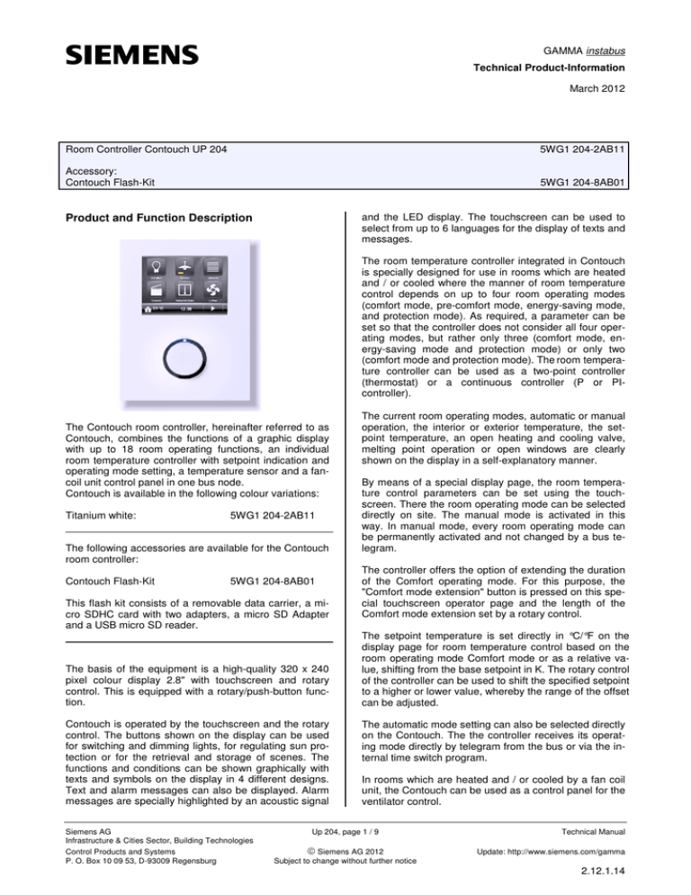
GAMMA instabus Technical Product-Information March 2012 Room Controller Contouch UP 204 5WG1 204-2AB11 Accessory: Contouch Flash-Kit 5WG1 204-8AB01 and the LED display. The touchscreen can be used to select from up to 6 languages for the display of texts and messages. Product and Function Description The room temperature controller integrated in Contouch is specially designed for use in rooms which are heated and / or cooled where the manner of room temperature control depends on up to four room operating modes (comfort mode, pre-comfort mode, energy-saving mode, and protection mode). As required, a parameter can be set so that the controller does not consider all four operating modes, but rather only three (comfort mode, energy-saving mode and protection mode) or only two (comfort mode and protection mode). The room temperature controller can be used as a two-point controller (thermostat) or a continuous controller (P or PIcontroller). The Contouch room controller, hereinafter referred to as Contouch, combines the functions of a graphic display with up to 18 room operating functions, an individual room temperature controller with setpoint indication and operating mode setting, a temperature sensor and a fancoil unit control panel in one bus node. Contouch is available in the following colour variations: Titanium white: 5WG1 204-2AB11 The following accessories are available for the Contouch room controller: Contouch Flash-Kit 5WG1 204-8AB01 This flash kit consists of a removable data carrier, a micro SDHC card with two adapters, a micro SD Adapter and a USB micro SD reader. The basis of the equipment is a high-quality 320 x 240 pixel colour display 2.8" with touchscreen and rotary control. This is equipped with a rotary/push-button function. Contouch is operated by the touchscreen and the rotary control. The buttons shown on the display can be used for switching and dimming lights, for regulating sun protection or for the retrieval and storage of scenes. The functions and conditions can be shown graphically with texts and symbols on the display in 4 different designs. Text and alarm messages can also be displayed. Alarm messages are specially highlighted by an acoustic signal Siemens AG Infrastructure & Cities Sector, Building Technologies Control Products and Systems P. O. Box 10 09 53, D-93009 Regensburg The current room operating modes, automatic or manual operation, the interior or exterior temperature, the setpoint temperature, an open heating and cooling valve, melting point operation or open windows are clearly shown on the display in a self-explanatory manner. By means of a special display page, the room temperature control parameters can be set using the touchscreen. There the room operating mode can be selected directly on site. The manual mode is activated in this way. In manual mode, every room operating mode can be permanently activated and not changed by a bus telegram. The controller offers the option of extending the duration of the Comfort operating mode. For this purpose, the "Comfort mode extension" button is pressed on this special touchscreen operator page and the length of the Comfort mode extension set by a rotary control. The setpoint temperature is set directly in °C/°F on the display page for room temperature control based on the room operating mode Comfort mode or as a relative value, shifting from the base setpoint in K. The rotary control of the controller can be used to shift the specified setpoint to a higher or lower value, whereby the range of the offset can be adjusted. The automatic mode setting can also be selected directly on the Contouch. The the controller receives its operating mode directly by telegram from the bus or via the internal time switch program. In rooms which are heated and / or cooled by a fan coil unit, the Contouch can be used as a control panel for the ventilator control. Up 204, page 1 / 9 Siemens AG 2012 Subject to change without further notice Technical Manual Update: http://www.siemens.com/gamma 2.12.1.14 GAMMA instabus Technical Product - Information March 2012 Room Controller Contouch UP 204 5WG1 204-2AB11 Accessory: Contouch Flash-Kit 5WG1 204-8AB01 The current fan speed is shown on the display. In manual operation, the speed level of the fan can be set by the rotary control on the Contouch. At speed level "0", the fan switches off and a possibly open valve closes, i.e. the room is then neither heated nor cooled. If the setpoint for heat protection is then exceeded or the setpoint for frost protection fallen short of, automatic mode becomes active in the case of a continuous controller and the fan is switched to the highest fan speed if a two-point controller is used. The controller heats or cools until reaching the setpoint of the previously set operating mode. With option "A", the Contouch rotary control is used to set the fan control to automatic mode. Then the speed is specified by the control system. The display lighting switches on when Contouch is operated. The lighting switches off after a certain time period, which must be configured. The device is in standby mode. Time programs with weekly switching plans can be configured for the 18 room operating functions and for setting the room operating mode of the controller. Up to 16 switching points can be set for each time switch program. The time switch programs for setting the room operating mode are activated in automatic mode. Contouch offers a cleaning function. If this has been activated by the touchscreen, then the device is blocked for servicing for a specific time period, which must be configured. The device, in particular the touchscreen, can be cleaned without triggering unwanted functions. The internal Contouch signal generator provides the acoustic display of alarm messages and can be used as a response when a button is activated. You use the ETS3 (Version 3 and higher) to select the application program, to allocate specific parameters and addresses and to transfer these into the Contouch UP 204 room controller. Application program Contouch room controller: 0705 Contouch room controller 970001 Technical Manual Update: http://www.siemens.com/gamma 2.12.1.14 The bus coupler contained in the scope of supply make it possible to connect the Contouch to the bus line by means of its user interface. The telegrams received through the bus line are processed by the bus coupler and forwarded to Contouch. In the opposite direction, signals coming from Contouch are converted into telegrams and sent through the bus. The bus coupler is connected directly to the bus, where it monitors this constantly and is therefore always informed as to whether the bus line is free or busy with telegrams. If an event occurs and the bus line is free, the bus coupler begins sending immediately. Otherwise the sending request is stored until the bus line is free. Note: Contouch can only be used together with the supplied bus coupler. Bus Coupler Technical Data Power supply Input voltage • Bus: DC 24V (DC 21...30 V), 10 mA • Booster voltage: DC 24 V (DC 12…30 V), 50 mA, from external SELV power supply • Recommended power supplies: DC 24V (before choke) from EIB power supply N125/21 Output voltage and current on Contouch • DC 3.3 V, > 150 mA Operating elements 1 learning key: To switch between normal and addressing modes Indicating elements 1 red LED: To display normal and addressing modes Connections • Bus line: Bus terminal (black/red) , screwless 0.6 ... 0.8 mm Ø solid • Power supply: Bus terminal (yellow-white), screwless 0.6...0.8 mm Ø, solid • 6-pole socket (AST) for connecting the Contouch Mechanical specifications • Casing plastic • Dimensions: Hole pitch: 72 x 72 mm mounting depth: 21 mm UP 204, page 2 / 9 Siemens AG 2012 Subject to change without further notice Siemens AG Infrastructure & Cities Sector, Building Technologies Control Products and Systems P. O. Box 10 09 53, D-93009 Regensburg GAMMA instabus Technical Product-Information March 2012 Room Controller Contouch UP 204 5WG1 204-2AB11 Accessories: Contouch Flash-Kit 5WG1 204-8AB01 Construction, location and functioning of the display and operating elements of the bus coupler • Weight: 58 g (with hanger) • Fire resistance: approx. 610 kJ • Assembly: is fastened to the flush-mounting box Electrical safety • Degree of contamination (acording to IEC 60664-1): 2 • Degree of protection (according to EN 60529): IP 20 • Protection class (according to IEC 61140): III • Overvoltage category class (according to IEC 606641): II • Bus: Secure low voltage SELV 24V DC • Auxiliary supply voltage SELV 24V DC • Device complies with EN 50491-3, EN 61558-2-6 and EN 61558-2-16 EMC criteria fulfills EN 50491-5-1, EN 50491-5-2, EN 50491-5-3 Environmental specifications • Resistance to climate EN 50090-2-2 • Ambient temperature in operation: - 5 ... + 45 °C • Storage temperature: - 25 ... + 70 °C • Relative humidity (non-condensing): 5% to 93% Approval mark KNX EIB EC marking to EMC directive (residential and functional building), low voltage guideline Control Products and Systems P. O. Box 10 09 53, D-93009 Regensburg A1 A3 A4 A4 A6 A5 A7 Figure 1: Location of the display and operating Elements Bus couplers Reliability • Failure rate: 136 fit at 40°C Siemens AG Infrastructure & Cities Sector, Building Technologies A2 A1 Red LED for indicating normal mode (LED Off) or addressing mode (LED On); it goes out automatically after transferring the physical address A2 Key for switching between normal mode and addressing mode for transferring the physical address A3 Nameplate for entering the physical address A4 Holes for the centring spikes for fastening the Contouch to the bus coupler A5 6-pin user interface (AST) for connecting the Contouch A6 Slots for fastening the bus coupler to the installation mounting box A7 Threads for the fixing screw (for the additional fastening of the Contouch, e.g. theft protection) UP 204, page 3 / 9 Siemens AG 2012 Subject to change without further notice Technical Manual Update: http://www.siemens.com/gamma 2.12.1.14 GAMMA instabus Technical Product - Information March 2012 Room Controller Contouch UP 204 5WG1 204-2AB11 Accessory: Contouch Flash-Kit 5WG1 204-8AB01 Technical data for the Room Controller Contouch Power supply Input voltage from the bus coupler via 6-pin plug connector • 3.3 V DC • Overvoltage category class (according to IEC 606641): II • Bus: Secure low voltage SELV 24V DC • Device complies with EN 50491-3, EN 61558-2-6 and EN 61558-2-16 Reliability • Failure rate: 1198,7 fit at 40°C Operating elements • Rotary control with rotary / push-button function • Touch display with touch function EMC criteria fulfills EN EN 50491-5-1, EN 50491-5-2, EN 50491-5-3 Indicating elements • 320 x 240 Pixel colour display 2.8" with touchscreen, 18 bit colour depth, effectively used 16 bit colour depth • RGB LED under the colourless, transparent ring around the rotary control/push-button; serves as orientation light to signal alarms and describe the start behaviour Environmental specifications • Resistance to climate EN 50090-2-2 • Ambient temperature in operation: - 5 ... + 45 °C • No direction sunlight • Storage temperature: - 25 ... + 70 °C • Relative humidity (non-condensing): 5% to 93% Temperature measurement • Measuring range: 0 ... + 40 °C • Resolution: 0.1 K • Accuracy in relation to the sensor temperature: ± 1,0 K under reference conditions ± 2.0 K under environmental condition and in the measuring range Approval mark • KNX EIB EC marking • according to EMC directive (residential and functional building), low voltage guideline Connections • 6-pin plug connector for attaching and connecting with the bus coupler Mechanical specifications • Casing plastic • Dimensions: - (L x W x D): 116 x 86 x 14 mm (without rotary/pushbutton and without plug connector guidance ), - (L x W x D): 116 x 86 x 24 mm (with rotary/pushbutton and without plug connector guidance ), - (L x W x D): 116 x 86 x 30 mm (with rotary/pushbutton and without plug connector guidance ), • Weight: 88 g • Fire resistance: approx. 2320 KJ • Mounting: The Contouch is attached to the bus coupler and screwed to its support frame with a Phillips screw M 2.5 x 5 (theft protection) Electrical safety • Degree of contamination (according to IEC 60664-1): 2 • Degree of protection (according to EN 60529): IP 20 • Protection class (according to IEC 61140): III Technical Manual Update: http://www.siemens.com/gamma 2.12.1.14 UP 204, page 4 / 9 Siemens AG 2012 Subject to change without further notice Siemens AG Infrastructure & Cities Sector, Building Technologies Control Products and Systems P. O. Box 10 09 53, D-93009 Regensburg GAMMA instabus Technical Product-Information March 2012 Room Controller Contouch UP 204 5WG1 204-2AB11 Accessories: Contouch Flash-Kit 5WG1 204-8AB01 Construction, location and functioning of the display and operating elements of the Contouch B1 C1 C2 C3 C1 B2 C4 C5 B3 Figure 3: Rear view of the Contouch unit C1 Figure 2: Location of the display and operating elements Front view of the Contouch unit C2 C3 B1 B2 B3 Touch display RGB LED Rotary control with push-button function C4 C5 Spikes for centring the Contouch on the Bus coupler 6-pin plug connector as user interface to the Bus coupler Screw for fastening the Contouch to the support frame of the bus coupler Insert for the micro SD card Temperature sensor Assembly, wiring and commissioning Connection example Bus coupler 6 Room controller: Contouch AST Siemens AG Infrastructure & Cities Sector, Building Technologies Control Products and Systems P. O. Box 10 09 53, D-93009 Regensburg UP 204, page 5 / 9 Siemens AG 2012 Subject to change without further notice Technical Manual Update: http://www.siemens.com/gamma 2.12.1.14 GAMMA instabus Technical Product - Information March 2012 Room Controller Contouch UP 204 5WG1 204-2AB11 Accessory: Contouch Flash-Kit 5WG1 204-8AB01 Installation notes • The system is used for fixed installation in dry internal areas for the installation of flush-mounting boxes. V WARNING • The system may only be installed and commissioned by a licensed electrician. • The device may not be inserted together in the same socket with 230V equipment and/or 230V cables. • The relevant safety and accident prevention rules are to be obeyed. • The system must not be opened. • When planning and installing electrical systems, the relevant national directives, rules and regulations of the country in question are to be obeyed. The bus terminal and supply terminal (terminal block) (E1) consist of two parts (E1.1, E1.2), each with four terminal contacts. You must take care that both test sockets (E1.3) are not damaged, either with the bus lead (accidental attempt to plug in) or with the screwdriver (when trying to remove the terminal).. Insert the screwdriver carefully into the wire insertion slot of the red/black or yellow/white part of the terminal and remove the terminal from the bus coupler (Figure 5). Note Do not lever the terminals outwards from below! Risk of short-circuit Attach bus terminal and supply terminal Plug the terminals into the guide grooves of the bus coupler and push the terminals downwards to the end stop. Connecting the bus and supply terminals • D1 • D2 The terminals (E1) are suitable for solid leads with a diameter of 0.6 ... 0.8 mm. Remove insulation on the ends of the leads (E1.4) and plug them into the terminal (E1) (red = +, black = -) or (yellow = +, white = -) (Fig. 6). E 1.4 E1 Figure 4: Connection of the bus and supply terminals The connection to the bus line (D1) and to the booster voltage (D2) is achieved using screwless plug-in terminals. Remove bus terminal and supply terminal The bus terminal (D1) and the supply terminal (D2) are located on the rear side of the bus coupler (Figure 4). 5 mm E 1.4 Figure 6: Connection and disconnection of leads If the bus line is connected with reverse polarity, then the bus coupler is switched off by a protective device (reverse polarity protection). This also applies for the required booster voltage. Disconnection of the bus and supply lines • E1 E1.3 E1.1 E1 Remove the terminal (E1) and pull out its lead (E1.4) by turning it alternately backwards and forwards (Figure 6). E1.2 Figure 5: Terminals Technical Manual Update: http://www.siemens.com/gamma 2.12.1.14 UP 204, page 6 / 9 Siemens AG 2012 Subject to change without further notice Siemens AG Infrastructure & Cities Sector, Building Technologies Control Products and Systems P. O. Box 10 09 53, D-93009 Regensburg GAMMA instabus Technical Product-Information March 2012 Room Controller Contouch UP 204 5WG1 204-2AB11 Accessories: Contouch Flash-Kit 5WG1 204-8AB01 Mounting G1 A screw connection is used to install the bus coupler in Ø 60 mm mounting boxes (see Fig. 7). G2 G3 F1 F2 Figure 8: Mounting of the Contouch F3 Starting up Figure 7: Assembly of the bus coupler F1 F2 F3 Mounting box (60 mm Ø in accordance with DIN 49073) Bus coupler Bus coupler fixing screws Note: The bus coupler must be mounted in such a way that the user interface (AST) is located at the bottom (see Fig. 1 or 7). Please ensure thereby that the Contouch to be attached to the AST is mounted in the correct position for operation. For a permanently secure contact connection to the AST, it is urgently recommended to lock the Contouch into place with the fixing screw. Siemens AG Infrastructure & Cities Sector, Building Technologies Control Products and Systems P. O. Box 10 09 53, D-93009 Regensburg - Fasten the bus coupler (F2) to the flash-mounting box (F1) and connect it to the bus line and the booster voltage. - Press the start-up button (A2): Start-up LED (A1) illuminates - Use the ETS to load the physical address and the configured application program - Use the two centring spikes (C1) and the 6-pin plug connector (C2) to attach Contouch to the bus coupler and screw this onto the support frame (G1) with the fixing screw (G2) (Theft protection) - Attach rotary/push-button (G3) to the Contouch Along with the user interface, Contouch is equipped with a removable data carrier (micro SDHS card). This flash card contains various files (Firmware and defined configuration settings) for the start-up of Contouch, which have been stored or generated by ETS plug-in. Thus, the removable data carrier is to be connected with the commissioning PC for every start-up. The Contouch flash kit, which is available as an accessory for the Contouch room controller, offers both adapters (micro SD Adapter and USB microSD reader) along with the micro SDHC card. The two adapters can be used to install the removable data carrier into the SD card slot or in the USB port of the commissioning PC. During start-up with the Contouch plug-in, the "generate" command is used to store the following files on the removable data carrier: RC-Programming-card.info rc.bin (Firmware Contouch) rcconfig.bin (Configuration Contouch) UP 204, page 7 / 9 Siemens AG 2012 Subject to change without further notice Technical Manual Update: http://www.siemens.com/gamma 2.12.1.14 GAMMA instabus Technical Product - Information March 2012 Room Controller Contouch UP 204 5WG1 204-2AB11 Accessory: Contouch Flash-Kit 5WG1 204-8AB01 The storage card is subsequently inserted into the Contouch micro SD card slot. For this purpose, the Contouch is removed from the bus coupler, Fig. 8. This occurs by removing the rotary/push-button (G3) and by loosening the safety screw (G2). After insertion of the micro SD card into the shaft (C4) on the Contouch (contacts point toward the front of the Contouch) and its attachment to the bus coupler, the Contouch is booted. In the process, the current Firmware and the configuration data are automatically loaded into the Contouch. The storage card should be removed again after restarting the Contouch (the main menu is displayed). This will considerably shorten the start behaviour of the Contouch. All changes have now been accepted and are now permanently stored in the memory. After completion of start-up, relock the Contouch to the bus coupler with the fixing screw and plug the rotary/push-button (G3) back into the Contouch. • care must be taken to ensure a low-vibration installation site Drafts from windows and doors must be avoided! Figure 9: Installation instructions for sensors and temperature controllers Note: If the micro SD card is changed without removing the Contouch from the bus coupler, then the device must be restarted for the data transfer. The device-side end of the installation tube must be sealed so that no drafts form in the tube which negatively affect the measurements, see Fig. 10. Micro SD and micro SDHC cards can be used as storage media. Dismounting - Remove rotary/push-button (G3) Unscrew the fixing screw (G2). Remove Contouch from the bus coupler Remove the bus coupler from the flush-mounting box Mounting site (see Fig. 9) Observe the following notes when mounting the Contouch room controller: Figure 10: Sealing of the installation tube Controller mounting on the interior wall of the room to be air-conditioned, opposite the heating source: • at a height of around 1.5 m in the occupied zone and at least 50 cm away from the nearest wall. • not on exterior walls • not in niches or behind curtains • not above or near heat sources or shelves • not on walls, behind which heat sources such as a fireplace are located • not in the radiation range of heat sources and lights such as spot lamps • not in areas with direct sunlight Technical Manual Update: http://www.siemens.com/gamma 2.12.1.14 UP 204, page 8 / 9 Siemens AG 2012 Subject to change without further notice Siemens AG Infrastructure & Cities Sector, Building Technologies Control Products and Systems P. O. Box 10 09 53, D-93009 Regensburg GAMMA instabus Technical Product-Information March 2012 Room Controller Contouch UP 204 5WG1 204-2AB11 Accessories: Contouch Flash-Kit 5WG1 204-8AB01 Dimensional drawing of the bus coupler Dimensions in mm 72 Ø 23.5 72 21 Dimensional drawing of Contouch 14 Dimensions in mm 10 44 86 56,4 42 116 642 General notes • The operating manual is to be handed over to the customer. • A defective device is to be sent back to the responsible sales office with a return shipping note. • If you have further questions concerning the product, please contact our Technical Support: ℡ +49 (911) 895-7222 +49 (911) 895-7223 support.automation@siemens.com www.siemens.de/automation/support-request Siemens AG Infrastructure & Cities Sector, Building Technologies Control Products and Systems P. O. Box 10 09 53, D-93009 Regensburg UP 204, page 9 / 9 Siemens AG 2012 Subject to change without further notice Technical Manual Update: http://www.siemens.com/gamma 2.12.1.14

