Voyager II - Orbit Irrigation Products
Anuncio
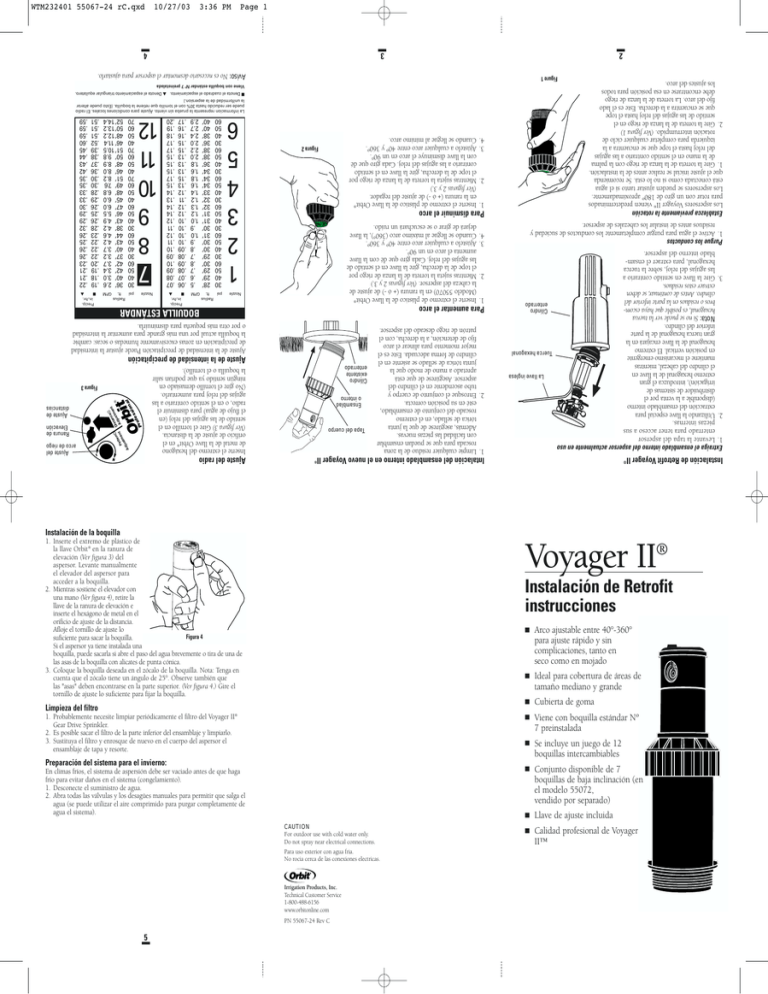
5 PN 55067-24 Rev C Irrigation Products, Inc. Technical Customer Service 1-800-488-6156 www.orbitonline.com CAUTION For outdoor use with cold water only. Do not spray near electrical connections. Para uso exterior con agua fria. No rocia cerca de las conexiones electricas. Calidad profesional de Voyager II™ Llave de ajuste incluida En climas fríos, el sistema de aspersión debe ser vaciado antes de que haga frío para evitar daños en el sistema (congelamiento). 1. Desconecte el suministro de agua. 2. Abra todas las válvulas y los desagües manuales para permitir que salga el agua (se puede utilizar el aire comprimido para purgar completamente de agua el sistema). 1. Probablemente necesite limpiar periódicamente el filtro del Voyager II Gear Drive Sprinkler. 2. Es posible sacar el filtro de la parte inferior del ensamblaje y limpiarlo. 3. Sustituya el filtro y enrosque de nuevo en el cuerpo del aspersor el ensamblaje de tapa y resorte. Viene con boquilla estándar Nº 7 preinstalada Preparación del sistema para el invierno: Conjunto disponible de 7 boquillas de baja inclinación (en el modelo 55072, vendido por separado) Se incluye un juego de 12 boquillas intercambiables ® Limpieza del filtro Cubierta de goma Professional Orbit Ideal para cobertura de áreas de tamaño mediano y grande Arco ajustable entre 40°-360° para ajuste rápido y sin complicaciones, tanto en seco como en mojado Instalación de Retrofit instrucciones Voyager II® Pattern Adjustment Dist ance Adjustment ® 1. Inserte el extremo de plástico de la llave Orbit® en la ranura de elevación (Ver figura 3) del aspersor. Levante manualmente el elevador del aspersor para acceder a la boquilla. 2. Mientras sostiene el elevador con una mano (Ver figura 4), retire la llave de la ranura de elevación e inserte el hexágono de metal en el orificio de ajuste de la distancia. Afloje el tornillo de ajuste lo Figura 4 suficiente para sacar la boquilla. Si el aspersor ya tiene instalada una boquilla, puede sacarla si abre el paso del agua brevemente o tira de una de las asas de la boquilla con alicates de punta cónica. 3. Coloque la boquilla deseada en el zócalo de la boquilla. Nota: Tenga en cuenta que el zócalo tiene un ángulo de 25°. Observe también que las "asas" deben encontrarse en la parte superior. (Ver figura 4.) Gire el tornillo de ajuste lo suficiente para fijar la boquilla. Instalación de la boquilla Instalación de Retrofit Voyager II® Intalación del ensamblado interno en el nuevo Voyager II® Ajuste del radio Inserte el extremo del hexágono de metal de la llave Orbit® en el orificio de ajuste de la distancia. (Ver figura 3) Gire el tornillo en el sentido de las agujas del reloj (en el flujo de agua) para disminuir el radio, o en el sentido contrario a las agujas del reloj para aumentarlo. (No gire el tornillo demasiado en ningún sentido ya que podrían salir la boquilla o el tornillo). A P bit Or Tapa del cuerpo s fe ro sio na l Ensamblad o interno Cilindro existente enterrado ce t tan men ® Dis just Ad 1. Limpie cualquier residuo de la zona roscada para que se puedan ensamblar con facilidad las piezas nuevas. Además, asegúrese de que la junta tórica de sellado, en el extremo roscado del conjunto de ensamblado, esté en su posición correcta. 2. Enrosque el conjunto de cuerpo y tubo ascendente en el cilindro del aspersor. Asegúrese de que está apretado a mano de modo que la junta tórica de sellado se asiente en el cilindro de forma adecuada. Este es el mejor momento para alinear el arco fijo de detención, a la derecha, con el patrón de riego deseado del aspersor. rn tte t Pa men st dju Extraiga el ensamblado interno del aspersor actualmente en uso 1. Levante la tapa del aspersor enterrado para tener acceso a sus piezas internas. 2. Utilizando la llave especial para extracción del ensamblado interno (disponible a la venta por el distribuidor de sistemas de irrigación), introduzca el gran La llave inglesa extremo hexagonal de la llave en el cilindro del cabezal, mientras mantiene el mecanismo emergente Tuerca hexagonal en posición vertical. El extremo hexagonal de la llave encajará en la gran tuerca hexagonal de la parte inferior del cilindro. Nota: Si no se puede ver la tuerca Cilindro hexagonal, es posible que haya escomenterrado bros o residuos en la parte inferior del cilindro. Antes de continuar, se deben extraer estos residuos. 3. Gire la llave en sentido contrario a las agujas del reloj, sobre la tuerca hexagonal, para extraer el ensamblado interno del aspersor. Ajuste del arco de riego Ranura de Elevación Ajuste de distancias Figura 3 Ajuste de la intensidad de precipitación Ajuste de la intensidad de precipitación Puede ajustar la intensidad de precipitación en zonas excesivamente humedas o secas: cambie la boquilla actual por una más grande para aumentar la intensidad o por otra más pequeña para disminuirla. BOQUILLA ESTÁNDAR Para aumentar el arco 1. Inserte el extremo de plástico de la llave Orbit® (Modelo 55070) en la ranura (+ ó -) de ajuste de la cabeza del aspersor. (Ver figuras 2 y 3.) 2. Mientras sujeta la torreta de la lanza de riego por el tope de la derecha, gire la llave en el sentido de las agujas del reloj. Cada giro que dé con la llave aumenta el arco en un 90°. 3. Ajústelo a cualquier arco entre 40º y 360º. 4. Cuando se llegue al máximo arco (360°), la llave dejará de girar o se escuchará un ruido. Nozzle Professional Orbit Pattern Adjustment Distance Adjustment ® Purgue los conductos 1. Active el agua para purgar completamente los conductos de suciedad y residuos antes de instalar los cabezales de aspersor. Establezca previamente la rotación Los aspersores Voyager II® vienen predeterminados para rotar con un giro de 180º aproximadamente. Los aspersores se pueden ajustar tanto si el agua está conectada como si no lo está. Se recomienda que el ajuste inicial se realice antes de la instalación. 1. Gire la torreta de la lanza de riego con la palma de la mano en el sentido contrario a las agujas del reloj hasta el tope que se encuentra a la izquierda para completar cualquier ciclo de rotación interrumpido. (Ver figura 1) 2. Gire la torreta de la lanza de riego en el sentido de las agujas del reloj hasta el tope que se encuentra a la derecha. Este es el lado fijo del arco. La torreta de la lanza de riego debe encontrarse en esa posición para todos los ajustes del arco. nret aP tnemtsujdA lanoisseforP tibrO ecnatsiD tnemtsujdA ® Para disminuir el arco 1. Inserte el extremo de plástico de la llave Orbit® en la ranura (+ ó -) de ajuste del regador. (Ver figuras 2 y 3.) 2. Mientras sujeta la torreta de la lanza de riego por el tope de la derecha, gire la llave en el sentido contrario a las agujas del reloj. Cada giro que dé con la llave disminuye el arco en un 90°. 3. Ajústelo a cualquier arco entre 40º y 360º. 4. Cuando se llegue al mínimo arco. Figura 2 1 2 3 4 5 6 psi 30 40 50 60 30 40 50 60 30 40 50 60 30 40 50 60 30 40 50 60 30 40 50 60 Radius ft. GPM 28’ 29’ 29’ 30’ 29’ 30’ 30’ 31’ 30’ 31’ 31’ 32’ 32’ 33’ 34’ 34’ 34’ 36’ 38’ 38’ 36’ 38’ 40’ 40’ .5 .6 .7 .8 .7 .8 .9 1.0 .9 1.0 1.2 1.3 1.2 1.4 1.6 1.8 1.6 1.8 2.0 2.2 2.0 2.4 2.7 2.9 Precip. in./hr. ▲ ■ .06 .07 .08 .09 .08 .09 .10 .10 .10 .10 .12 .12 .11 .12 .13 .15 .13 .13 .13 .15 .15 .16 .16 .17 .07 .08 .09 .10 .09 .10 .11 .12 .11 .12 .14 .14 .13 .14 .15 .17 .15 .15 .15 .17 .17 .18 .19 .20 Nozzle 7 8 9 10 11 12 Radius ft. GPM psi 30 40 50 60 30 40 50 60 30 40 50 60 40 50 60 70 40 50 60 70 40 50 60 70 36’ 2.6 40’ 3.0 42’ 3.4 42’ 3.7 37’ 3.2 40’ 3.7 43’ 4.2 44’ 4.6 38’ 4.2 43’ 4.9 46’ 5.5 47’ 6.0 45’ 6.0 48’ 6.8 49’ 7.6 51’ 8.2 46’ 8.0 48’ 8.9 50’ 9.8 51’10.5 46’ 11.4 48’12.2 50’13.2 52’14.4 Precip. in./hr. ▲ ■ .19 .18 .19 .20 .22 .22 .22 .23 .28 .26 .25 .26 .29 .28 .30 .30 .36 .37 .38 .39 .52 .51 .51 .51 .22 .21 .21 .23 .26 .26 .25 .26 .32 .29 .29 .30 .33 .33 .35 .35 .42 .43 .44 .45 .60 .59 .59 .59 La informacion representa la prueba sin viento. Ajuste para condiciones locales. El radio puede ser reducido hasta 30% con el tornillo que retiene la boquilla. (Esto puede alterar la uniformidad de la aspersion.) ■ Denota el cuadrado el espaciamiento. ▲ Denota el espaciamiento triangular equilatero. Viene con boquilla estándar Nº 7 preinstalada Figure 1 Aviso: No es necesario desmontar el aspersor para ajustarlo. 3 4 10/27/03 3:36 PM 2 WTM232401 55067-24 rC.qxd Page 1 5 PN 55067-24 Rev C Irrigation Products, Inc. Technical Customer Service 1-800-488-6156 www.orbitonline.com In freezing climates, your sprinkler system must be drained prior to freezing to prevent damage. 1. Turn off the water supply. 2. Open all valves and manual drains to allow water to escape (compressed air can be used to completely purge the system of water). Winterizing Your System CAUTION For outdoor use with cold water only. Do not spray near electrical connections. Para uso exterior con agua fria. No rocia cerca de las conexiones electricas. 1. Your Voyager II® Gear Drive Sprinkler filter may need to be cleaned periodically. To access the filter, unscrew the cap and remove the cap/spring assembly from the body. 2. The filter can be pulled out from the bottom of the assembly and cleaned. If necessary use pliers. 3. Replace the filter and screw the cap/spring assembly back on the sprinkler body. ® Professional Rubber cover Ideal for medium to large area coverage 40°-360° adjustable arc for fast, hassle-free adjustment, wet or dry Retrofit Sprinkler Instructions Voyager II® Pattern Adjustment Dist ance Adjustment Orbit Voyager II® professional quality Adjustment key included Set of 7 low-angle nozzles available (Model 55072, sold separately) Set of 12 interchangeable nozzles included Cleaning the Filter Comes with pre-installed, Standard #7 nozzle 1. Insert the plastic end of the Orbit® key into the lifting socket (Figure 3) of the sprinkler. Pull the riser up to gain access to the nozzle socket. 2. While holding the riser up with one hand (Figure 4), remove the key from the lifting socket and insert the metal hex end into the distance adjustment socket. Figure 4 Loosen the adjustment screw far enough to clear the nozzle. If a nozzle is already installed in the sprinkler, it can be removed by briefly turning on the water, or by pulling on one of the nozzle “ears” with needle-nose pliers. 3. Slip the desired nozzle into the nozzle socket. Note that the socket is angled up 25°. Also note that the “ears” should be located at the top. (See Figure 4.) Rotate the adjustment screw in far enough to secure the nozzle. Nozzle Installation Installation of Retrofit Voyager II® Radius Adjustment Installing the new Voyager II ® internal assembly 1. Clean any debris in the thread area for easy assembly of the new parts. Body cap Also make sure the O-ring seal on the threaded end of the stem assembly is in place. Internal 2. Thread the entire body/riser assemassembly bly into the existing sprinkler canExisting ister. Make sure this assembly is in-ground hand tight so that the O-ring seal canister seats properly in the existing canister. At this time, it is usually most convenient to align the right, fixed arc stop of the sprinkler's intended watering pattern. A Insert the metal hex end of the Orbit® key into the distance adjustment socket. (See Figure 3.) Turn the screw clockwise (into the stream of water) to decrease the radius, or counterclockwise to increase the radius. (Do not rotate the screw too far either way or the nozzle or screw may come out.) Pattern Adjustment Socket P bit Or s fe ro Lifting Socket sio na l Distance Adjustment Socket Figure 3 Precipitation Rate Adjustment For excessively wet or dry areas, the precipitation rate can be adjusted: replace the existing nozzle with a larger one to increase the rate or a smaller one to decrease the rate of precipitation. STANDARD NOZZLES To Increase the Arc 1. ce t tan men ® Dis just Ad Wrench Hex nut In-ground canister 2. Nozzle Professional Orbit Pattern Adjustment Distance Adjustment ® 3. 4. Insert the plastic end of the Orbit® key (Model 55070) into the pattern adjustment socket. (See Figures 2 & 3.) While holding the nozzle turret at the right stop, turn the key clockwise. Each full turn of the key increases the arc 90°. Adjust to any arc between 40° and 360°. When the maximum arc (360°) is reached, the key will stop turning or there will be a ratcheting noise. To Decrease the Arc 1. 2. 3. 4. rn tte t Pa men st dju Remove the internal assembly of the existing sprinkler 1. Pry up the lid on the in-ground sprinkler to gain access to the internal parts. 2. Using the special internal assembly removal wrench (available from your irrigation distributor), insert the large hex end of the wrench into the canister of the head while holding the pop-up mechanism upright. The hex end of the wrench will fit onto the large hex nut at the bottom of the canister. Note: If the hex nut is not visible, there may be debris in the bottom of the canister. This debris should be removed before continuing. 3. Turn the wrench counterclockwise on the hex nut to remove the internal assembly of the sprinkler. Flush Lines 1. Turn the water on to thoroughly flush the lines of dirt and debris before installing any sprinkler heads. Pre-Set the Rotation Voyager II® sprinklers are preset to rotate approximately 180°. Sprinklers may be adjusted with water on or off. It is recommended that initial adjustment be made before installation. 1. Using the palm of you hand, rotate the nozzle turret counterclockwise to the left stop to complete any interrupted rotation cycle. (See Figure 1.) 2. Rotate the nozzle turret clockwise to the right stop. This is the fixed side of the arc. The nozzle turret must be held in this position for all arc adjustments. nret aP tnemtsujdA lanoisseforP tibrO e c n at s i D tnemtsujdA ® Insert the plastic end of the Orbit® key into the pattern adjustment socket. (See Figures 2 & 3.) While holding the nozzle turret at the right stop, turn the key counterclockwise. Each full turn of the key decreases the arc 90°. Adjust to any arc between 40° and 360°. When the minimum arc (40°) is reached, the key will stop turning or there will be a ratcheting noise. Figure 2 1 2 3 4 5 6 psi 30 40 50 60 30 40 50 60 30 40 50 60 30 40 50 60 30 40 50 60 30 40 50 60 Precip. in./hr. ▲ Radius ft. GPM 28’ 29’ 29’ 30’ 29’ 30’ 30’ 31’ 30’ 31’ 31’ 32’ 32’ 33’ 34’ 34’ 34’ 36’ 38’ 38’ 36’ 38’ 40’ 40’ ■ .5 .6 .7 .8 .7 .8 .9 1.0 .9 1.0 1.2 1.3 1.2 1.4 1.6 1.8 1.6 1.8 2.0 2.2 2.0 2.4 2.7 2.9 .06 .07 .08 .09 .08 .09 .10 .10 .10 .10 .12 .12 .11 .12 .13 .15 .13 .13 .13 .15 .15 .16 .16 .17 .07 .08 .09 .10 .09 .10 .11 .12 .11 .12 .14 .14 .13 .14 .15 .17 .15 .15 .15 .17 .17 .18 .19 .20 Nozzle 7 8 9 10 11 12 Radius ft. GPM psi 30 40 50 60 30 40 50 60 30 40 50 60 40 50 60 70 40 50 60 70 40 50 60 70 36’ 2.6 40’ 3.0 42’ 3.4 42’ 3.7 37’ 3.2 40’ 3.7 43’ 4.2 44’ 4.6 38’ 4.2 43’ 4.9 46’ 5.5 47’ 6.0 45’ 6.0 48’ 6.8 49’ 7.6 51’ 8.2 46’ 8.0 48’ 8.9 50’ 9.8 51’10.5 46’ 11.4 48’12.2 50’13.2 52’14.4 Precip. in./hr. ▲ ■ .19 .18 .19 .20 .22 .22 .22 .23 .28 .26 .25 .26 .29 .28 .30 .30 .36 .37 .38 .39 .52 .51 .51 .51 .22 .21 .21 .23 .26 .26 .25 .26 .32 .29 .29 .30 .33 .33 .35 .35 .42 .43 .44 .45 .60 .59 .59 .59 Data represent test results in zero wind. Adjust for local conditions. Radius can be reduced by up to 30% with nozzle retaining screw. (This may alter the uniformity of the spray pattern.) ■ Denotes square spacing. ▲ Denotes equilateral triangular spacing. Your Voyager II® Pop-Up Sprinkler comes with a pre-installed, Standard #7 nozzle. Figure 1 Note: It is not necessary to disassemble the sprinkler to make adjustments. 3 4 10/27/03 3:36 PM 2 WTM232401 55067-24 rC.qxd Page 2
