MR MR MR MR MR MR
Anuncio

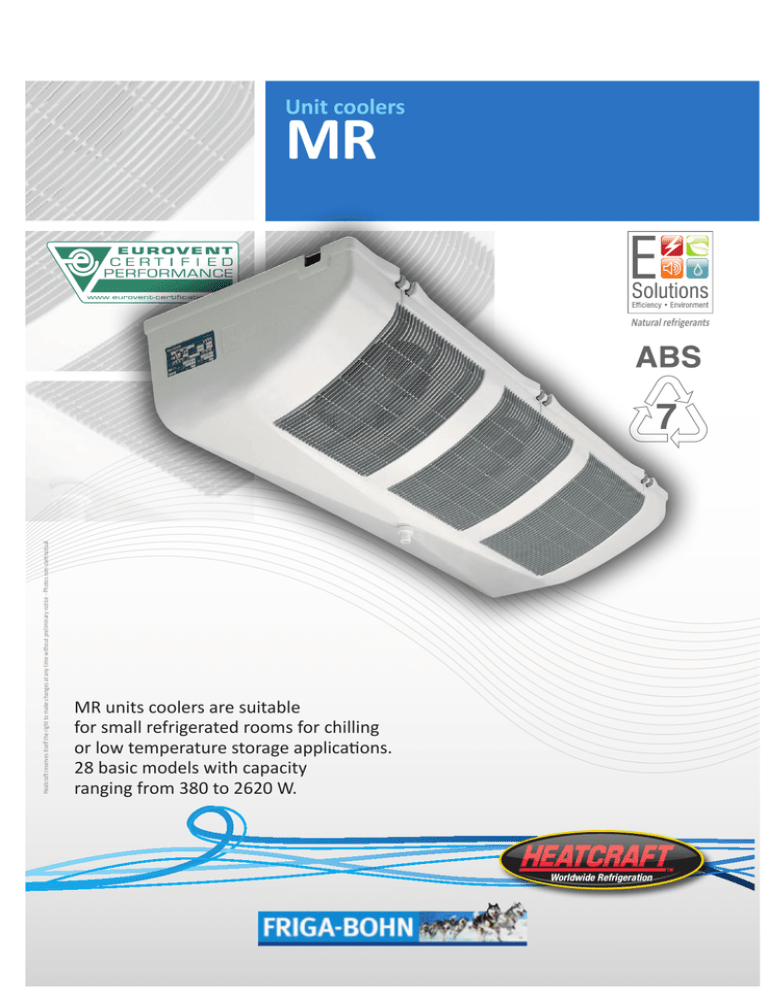
Unit coolers MR Natural refrigerants Heatcraft reserves itself the right to make changes at any time without preliminary notice - Photos non-contractual 7 MR units coolers are suitable for small refrigerated rooms for chilling or low temperature storage applications. 28 basic models with capacity ranging from 380 to 2620 W. Accessibility Unit coolers MR • The MR line has been designed to facilitate easy installation, maintenance and cleaning. Casing fitted with polyamid hinges, enables full access to all unit components (coil, motorfan, defrost heater, connections,...). These hinges allow the casing removal, too. Nomenclature MRE 210 E (1) Coil with a polyester painting protection (2) (3) (1) Unit cooler: MR : positive temp. application without defrost system MRE : negative temp. application with defrost system (2) Model (3) Fins spacing : R / E : 4.23 mm - L / C : 6.35 mm Description Casing • ABS recyclabe casing guarantees a high quality level with regard to: - robustness: high thermal (at low and high temperatures) and mechanical shock-proof characteristics, - aesthetics: its look, its finish and granulated white casing make the MR integrate completely with its installed environment, MR fins with polyester finish, - hygiene: no water retaining areas favourable to germ development due to its round cornered casing and no corrosive elements (for example: stainless steel screws), - safety: no sharp or cutting edges. Ventilation • 50-60 Hz fan assembly (Ø 200 mm) used for MR and MRE models, is designed with an enclosed frame, class B, impedance protected, life lubricated motor, connected to the junction box (except for MR 75/65). • Fan guards conform to safety regulations. Coil • The high efficient and compact MR range finned coils, are designed with corrugated aluminium fins (fin spacing: 4.23 or 6,35 mm) and grooved internal structure copper tubes. • The refrigerant distributors are Venturi type for models MR 160/140 to MR 270/250 and MRE 135/120 to MRE 270/250. • The whole MR coil has a polyester painting protection, particularly for corrosive atmospheres. Defrost • 230 V /1 tubular electric heater connected to a junction box (MRE only) is inserted in slots, under the coil which facilitates easy maintenance and ensures equal heat distribution through the coil. So, defrost is perfect. • Defrost water is collected in an intermediate drain pan then drained through a Ø 1” G threaded polyamid drain fitting. Options Coil WCO CO2 Glycol water, brine (please consult us). R744 optimzation (please consult us). Defrost E1K THD (MRE) Light electric defrosting: MR ... R and MR ... L. For low temperature refrigerated rooms, defrost termination and fan delay thermostat with single-pole, double throw switch at +12 °C (±3 K) and +2 °C (±3 K). Supplied with a sensor and a fitting clamp. Fully equipped unit coolers EEC Fully equipped unit cooler (see pages “APPENDIX”). E U R O V E N T CERTIFIED PERFORMANCE CERTIFY ALL DX AIR COOLERS AIR COOLED CONDENSERS DRY COOLERS EUROVENT - The performance published of our products are certified in conformity with european standards EN327, EN328, EN1048. ISO 9001 - Our company is certified by LRQA to comply with quality standards ISO 9001. RoHS - WEEE - Our products are compliant with regards to european guideline 2002/95/CE and 2002/96/CE concerning electric and enlectronic components. CE - Our products are in conformity with european guidelines. GOST - Products in conformity with "GOST" agreement. "According the requirements of the European measures, we draw your attention to the fact that our technical documents are at least translated into french and english. For any translation in another language such as the end user can require it, thank you to consult us." 20 - Unit coolers es. R404A MR ... tA1 +10°C +E1K +2°C MFE ... -5°C -10°C -25°C MR ... 4,23 mm Capacity Surface Circuit volume Air flow DT1 = 8K - SC 2 (1) 110 135 160 180 210 270 1070 3,66 0,63 650 3,7 2 2 x 38 2 x 0,24 7,5 784 596 3/8” 10 mm ** 1270 6,10 1,05 580 3,5 2 2 x 38 2 x 0,24 9,5 784 596 3/8” 10 mm ** 1550 8,04 1,1 880 4,1 3 3 x 38 3 X 0,24 14,5 1174 493 1860 8,04 1,38 880 4,1 3 3 x 38 3 X 0,24 14,5 1174 493 2060 10,05 1,73 870 4 3 3 x 38 3 x 0,24 15 1174 493 2620 13,40 2,30 1160 4,5 4 4 x 38 4 x 0,24 20 1504 658 D 1/2” *** D 1/2” *** D 1/2” *** D 1/2” *** 3/8” 10 mm 3/8” 10 mm 1/2” 12 mm 1/2” 12 mm 1/2” 12 mm 1/2” 12 mm Inlet Ø ODF * Outlet Ø ODF * 3/8” 10 mm 230 V/1/50 Hz Net weight A B Dimensions 75 W m2 dm3 m3/h m Num. W max A max (3) kg mm mm 680 3,35 0,58 290 3 1 1 x 38 1 x 0,24 3 514 326 3/8” 10 mm ** Air throw (2) Ø 200 mm Fan 230 V/1/50-60 Hz 1500 r.p.m. MR ... R Connections MR ... 6,35 mm Capacity Glycol water (4) Surface Circuit volume Air flow DT1 = 8K - SC 2 (1) DT1 = 8K - SC 2 (1) 100 120 140 170 190 250 890 2,53 0,63 660 3,7 2 2 x 38 2 x 0,24 7,5 784 596 3/8” 10 mm ** 1180 1220 4,22 1,05 620 3,5 2 2 x 38 2 x 0,24 9,5 784 596 3/8” 10 mm ** 1370 1150 5,56 1,10 960 4,1 3 3 x 38 3 x 0,24 14,5 1174 493 1680 5,56 1,38 960 4,1 3 3 x 38 3 x 0,24 14,5 1174 493 1890 1790 6,96 1,73 930 4 3 3 x 38 3 x 0,24 15 1174 493 2440 2380 9,27 2,30 1240 4,5 4 4 x 38 4 x 0,24 20 1504 658 D 1/2” *** D 1/2” *** D 1/2” *** D 1/2” *** 3/8” 10 mm 3/8” 10 mm 1/2” 12 mm 1/2” 12 mm 1/2” 12 mm 1/2” 12 mm Inlet Ø ODF * Outlet Ø ODF * 3/8” 10 mm 230 V/1/50 Hz Net weight A B Dimensions 65 W W m2 dm3 m3/h m Num. W max A max (3) kg mm mm 620 2,32 0,58 310 3 1 1 x 38 1 x 0,24 3 514 326 3/8” 10 mm ** Air throw (2) Ø 200 mm Fan 230 V/1/50-60 Hz 1500 r.p.m. MR ... L Connections (1) See pages “APPENDIX”. (2) Effective when the room cross section allows air circulation (see CECOMAF GT 6001, DIN8955, ENV328). (3) Setting of overload protections. For room temperatures ‘ti’ other than +20 °C, multiply the given amperage by the ratio 293/ (273 + ‘ti’) so as to obtain the approximate amperage after the room pull down. = A B (4) Glycol water : Percentage of glycol = 30% Fluid inlet temp. = -8°C Fluid outlet temp. = -4°C Dry air inlet temp. = +2°C Relative humidity = 85% * ODF: Female sweat type connection. ** Adapter parts supplied for Ø 1/2” or Ø 12 mm expansion valve to be brazed. *** Liquid distributor: Ø 1/2” male to be brazed. Adapter part supplied for either Ø 12 mm expansion valve to be brazed. 51 A B 208 209ˇ 18 mm 180 mini 9 18 = 438 90 * = B Ø 1" G = * 90 mini: Casing opening 160 mini: Casing removal es, as MR ... WCO A� CO2 E1K THD EEC - O - O Unit coolers - 21 R404A MR ... tA1 +10°C +E1K +2°C MRE ... -5°C -10°C -25°C MRE ... 4,23 mm MRE ... E DT1 = 7K - SC 3 (1) DT1 = 6K - SC 4 (1) Capacity Surface Circuit volume Air flow W W m2 dm3 m3/h m Num. W max A max (3) W A kg mm mm Air throw (2) Ø 200 mm Fan 230 V/1/50-60 Hz 1500 r.p.m. 230 V/1/50 Hz Electric defrost 230 V/1/50 Hz Net weight A B Dimensions Connections Inlet Ø ODF * Outlet Ø ODF * 75 110 530 420 3,35 0,58 290 3 1 1 x 38 1 x 0,24 400 1,8 3 514 326 3/8” 10 mm ** 3/8” 10 mm 820 640 3,66 0,63 650 3,7 2 2 x 38 2 x 0,24 440 2,0 7,5 784 596 3/8” 10 mm ** 3/8” 10 mm 65 100 135 160 180 210 270 1070 840 6,10 1,05 580 3,5 2 2 x 38 2 x 0,24 730 3,3 9,5 784 596 1210 960 8,04 1,1 880 4,1 3 3 x 38 3 X 0,24 960 4,4 14,5 1174 493 1440 1140 8,04 1,38 880 4,1 3 3 x 38 3 X 0,24 960 4,4 14,5 1174 493 1660 1320 10,05 1,73 870 4 3 3 x 38 3 x 0,24 1200 5,5 15 1174 493 2230 1780 13,40 2,30 1160 4,5 4 4 x 38 4 x 0,24 1600 7,3 20 1504 658 D 1/2” *** D 1/2” *** D 1/2” *** D 1/2” *** D 1/2” *** 1/2” 12 mm 5/8” 16 mm 5/8” 16 mm 5/8” 16 mm 3/4” 18 mm 120 140 170 190 MRE ... 6,35 mm MRE ... C DT1 = 7K - SC 3 (1) DT1 = 6K - SC 4 (1) Capacity Surface Circuit volume Air flow W W m2 dm3 m3/h m Num. W max A max (3) W A kg mm mm Air throw (2) Ø 200 mm Fan 230 V/1/50-60 Hz 1500 r.p.m. 230 V/1/50 Hz Electric defrost 230 V/1/50 Hz Net weight A B Dimensions Connections Inlet Ø ODF * Outlet Ø ODF * 480 380 2,32 0,58 310 3 1 1 x 38 1 x 0,24 400 1,8 3 514 326 3/8” 10 mm ** 3/8” 10 mm 670 540 2,53 0,63 660 3,7 2 2 x 38 2 x 0,24 440 2,0 7,5 784 596 3/8” 10 mm ** 3/8” 10 mm 250 950 760 4,22 1,05 620 3,5 2 2 x 38 2 x 0,24 730 3,3 9,5 784 596 1080 850 5,56 1,10 960 4,1 3 3 x 38 3 x 0,24 960 4,4 14,5 1174 493 1310 1040 5,56 1,38 960 4,1 3 3 x 38 3 x 0,24 960 4,4 14,5 1174 493 1510 1210 6,96 1,73 930 4 3 3 x 38 3 x 0,24 1200 5,5 15 1174 493 2030 1630 9,27 2,30 1240 4,5 4 4 x 38 4 x 0,24 1600 7,3 20 1504 658 D 1/2” *** D 1/2” *** D 1/2” *** D 1/2” *** D 1/2” *** 1/2” 12 mm 5/8” 16 mm 5/8” 16 mm 5/8” 16 mm 3/4” 18 mm (1) See pages “APPENDIX”. (2) Effective when the room cross section allows air circulation (see CECOMAF GT 6001, DIN8955, ENV328). (3) Setting of overload protections. For room temperatures ‘ti’ other than +20 °C, multiply the given amperage by the ratio 293/(273 + ‘ti’) so as to obtain the approximate amperage after the room pull down. * ODF: Female sweat type connection. ** Adapter parts supplied for Ø 1/2” or Ø 12 mm expansion valve to be brazed. *** Liquid distributor: Ø 1/2” male to be brazed. Adapter part supplied for either Ø 12 mm expansion valve to be brazed. = A B 51 A B 208 209ˇ 18 mm 180 mini 9 18 = 438 90 * = B Ø 1" G = * 90 mini: Casing opening 160 mini: Casing removal WCO MRE ... 22 - Unit coolers - CO2 A� E1K THD EEC O - O


