SEC99A UltraCap Armored Capillary and SEC99B Ultratube
Anuncio
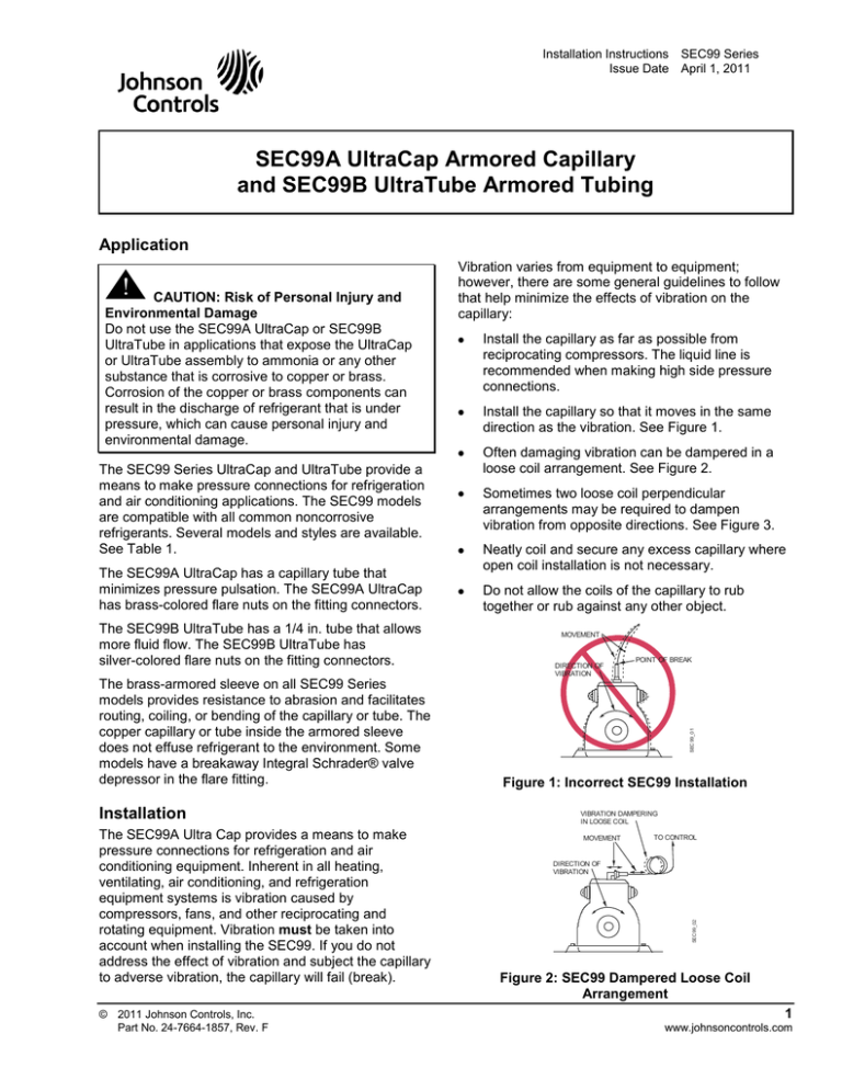
Installation Instructions SEC99 Series Issue Date April 1, 2011 SEC99A UltraCap Armored Capillary and SEC99B UltraTube Armored Tubing Application The SEC99 Series UltraCap and UltraTube provide a means to make pressure connections for refrigeration and air conditioning applications. The SEC99 models are compatible with all common noncorrosive refrigerants. Several models and styles are available. See Table 1. The SEC99A UltraCap has a capillary tube that minimizes pressure pulsation. The SEC99A UltraCap has brass-colored flare nuts on the fitting connectors. The SEC99B UltraTube has a 1/4 in. tube that allows more fluid flow. The SEC99B UltraTube has silver-colored flare nuts on the fitting connectors. The brass-armored sleeve on all SEC99 Series models provides resistance to abrasion and facilitates routing, coiling, or bending of the capillary or tube. The copper capillary or tube inside the armored sleeve does not effuse refrigerant to the environment. Some models have a breakaway Integral Schrader® valve depressor in the flare fitting. Installation The SEC99A Ultra Cap provides a means to make pressure connections for refrigeration and air conditioning equipment. Inherent in all heating, ventilating, air conditioning, and refrigeration equipment systems is vibration caused by compressors, fans, and other reciprocating and rotating equipment. Vibration must be taken into account when installing the SEC99. If you do not address the effect of vibration and subject the capillary to adverse vibration, the capillary will fail (break). © 2011 Johnson Controls, Inc. Part No. 24-7664-1857, Rev. F Install the capillary as far as possible from reciprocating compressors. The liquid line is recommended when making high side pressure connections. Install the capillary so that it moves in the same direction as the vibration. See Figure 1. Often damaging vibration can be dampered in a loose coil arrangement. See Figure 2. Sometimes two loose coil perpendicular arrangements may be required to dampen vibration from opposite directions. See Figure 3. Neatly coil and secure any excess capillary where open coil installation is not necessary. Do not allow the coils of the capillary to rub together or rub against any other object. MOVEMENT DIRECTION OF VIBRATION POINT OF BREAK SEC 99_01 CAUTION: Risk of Personal Injury and Environmental Damage Do not use the SEC99A UltraCap or SEC99B UltraTube in applications that expose the UltraCap or UltraTube assembly to ammonia or any other substance that is corrosive to copper or brass. Corrosion of the copper or brass components can result in the discharge of refrigerant that is under pressure, which can cause personal injury and environmental damage. Figure 1: Incorrect SEC99 Installation VIBRATION DAMPERING IN LOOSE COIL MOVEMENT TO CONTROL DIRECTION OF VIBRATION SEC99_02 ! Vibration varies from equipment to equipment; however, there are some general guidelines to follow that help minimize the effects of vibration on the capillary: Figure 2: SEC99 Dampered Loose Coil Arrangement 1 www.johnsoncontrols.com DIRECTION OF VIBRATION COILS E-W SEC 99_03 COILS N-S Figure 3: SEC99 Loose Coil Perpendicular Arrangement Note: You may require a double coil arrangement if vibration in different directions is present. Use a bracket or brace between the coils, if necessary. After considering the vibration effect, follow these instructions to install an SEC99 Series UltraCap or UltraTube: ! CAUTION: Risk of Environmental and Property Damage Avoid sharp bends in capillary tubes. Sharp bends can weaken or kink capillary tubes, which may result in refrigerant leaks or restrictions of flow. ! CAUTION: Risk of Environmental and Property Damage Coil and secure excess capillary tubing away from contact with sharp or abrasive objects or surfaces. Vibration or sharp or abrasive objects in contact with capillary tubes can cause damage that may result in refrigerant leaks, which may result in damage to the environment or property. Straight Fitting o 90 Fitting Distance from coil to fitting must be at least 1 in. (25 mm) Interior diameter of coiled capillary must be at least 2 in. (50 mm) for SEC99A UltraCap and at least 4 in. (102 mm) for SEC99B UltraTube. SEC 99_04 Note: It may be necessary to secure the capillary to a bracket or brace to quiet the vibration. The capillary may need to be secured in more than one place. 1. Uncoil the capillary or tube as needed (Figure 4). 2. Hand-start the flare nuts to avoid damaging the fitting threads. Note: If the fitting flare nut cannot be tightened onto the male flare fitting, it may be necessary to remove the Schrader valve depressor. See Removing the Breakaway Schrader Valve Depressor on page 2. Figure 4: SEC99 Installation Requirements Note: A bracket or brace may be required depending on vibration. 3. Use a 5/8 in. wrench to tighten the flare nuts. Do not apply more than 10 lb·ft (13.6 N·m) of torque. Removing the Breakaway Schrader Valve Depressor If you cannot hand tighten the SEC99 flare nut onto the male flare fitting, remove the snap-off Schrader valve depressor as follows: 4. Check all fittings and connections for leaks before placing the system into operation. 5. Insert the tip of a pair of needle-nose pliers as shown in Figure 5. Armored Sleeve Flare Nut Capillary Tube Breakaway Schrader Valve Depressor SEC 99_05 6. Apply firm pressure to snap off the Schrader valve depressor. Figure 5: Removing the Schrader Valve Depressor 2 SEC99A UltraCap Armored Capillary and SEC99B UltraTube Armored Tubing Installation Instructions Repairs and Replacement Do not attempt to repair a damaged SEC99 UltraCap or UltraTube. Contact the nearest Johnson Controls/Penn® representative to obtain a replacement. Table 1: SEC99 Series Dimensions and Physical Features Selection Matrix Series First Fitting Type and Internal Letter Capillary/Tube Diameter SEC99 A B 1/4 in. SAE Female Flare with a 0.06 in. (1.5 mm) Internal Diameter Capillary 1/4 in. SAE Female Flare with a 0.2 in. (5 mm) Internal Diameter Tube Second First Tube Angle and Letter Depressor Second Tube Angle and Depressor A Straight, with Depressor Straight, without Depressor B Straight, with Depressor 90 , with Depressor C D E F Straight, with Depressor Straight, without Depressor Straight, without Depressor 90 , without Depressor 90 , without Depressor 90 , without Depressor Straight, without Depressor 90 , without Depressor Technical Specifications Product Fittings Materials Style Capillary Diameter Shape Outside Inside Ambient Operating Conditions Maximum Working Pressure Burst Pressure Suggested Torque to Seal Compliance SEC99A UltraCap /SEC99B UltraTube SEC99A: Forged brass nut with copper stem SEC99B: Silver-color plated forged brass nut with copper stem 1/4 in. SAE female flare connector with breakaway Schrader valve depressor (depending on type selected) Straight or 90 elbow SEC99A 0.125 in. (3.1 mm), SEC99B 0.250 in. (6.3 mm) SEC99A 0.06 in. (1.5 mm), SEC99B 0.2 in. (5 mm) -50 to 300 F (-46 to 149 C), 95% RH 690 psig (4,757 kPa) 3,450 psig (23,786 kPa) 8 to 10 lb·ft (10.9 to 13.6 N·m) UL Recognized: File SA9457, CCN SFCS2 UL Recognized for Canada: SA9457, CCN SFCS8 The performance specifications are nominal and conform to acceptable industry standards. For application at conditions beyond these specifications, consult Johnson Controls/PENN Application Engineering at 1-800-275-5676. Johnson Controls, Inc. shall not be liable for damages resulting from misapplication or misuse of its products. Controls Group 507 E. Michigan Street P.O. Box 423 Milwaukee, WI 53201 Published in U.S.A. www.johnsoncontrols.com SEC99A UltraCap Armored Capillary and SEC99B UltraTube Armored Tubing Installation Instructions 3 SEC99A UltraCap Capilar Blindado y SEC99B UltraTube Tubo Blindado Aplicación ! PRECAUCIÓN: Riesgo de Lesión Personal y Daño Ambiental: No use el UltraCap SEC99A ni el UltraTube SEC99B en aplicaciones que expongan al ensamble UltraCap o UltraTube al amoniaco o a cualquier otra sustancia corrosiva al cobre o latón. La corrosión de dichos componentes puede resultar en la descarga de refrigerante bajo presión, pudiendo causar daños personales o ambientales. La serie SEC99 de UltraCap y UltraTube ofrece conexiones de presión para aplicaciones de refrigeración y aire acondicionado. Los modelos SEC99 son compatibles con todos los refrigerantes comunes no corrosivos. Hay varios modelos y estilos disponibles. Ver la Table 1. El UltraCap SEC99A tiene un tubo capilar que minimiza pulsaciones de presión; además, tiene tuercas color latón tipo campana en los conectores. El UltraTube SEC99B tiene un tubo de 1/4" que permite un mayor flujo; además, tiene tuercas acampanadas color plata tipo campana en los conectores. El Blindaje de bronce de todos los modelos de la Serie SEC99 provee resistencia a la abrasión y facilita la orientación, enrollado, o doblado del tubo capilar. El tubo capilar de cobre dentro de la manga de bronce no derrama refrigerante al medio ambiente. Algunos modelos tienen depresor removible de válvula Integral Schrader® en el conector tipo campana. La vibración varía de equipo a equipo; sin embargo, hay algunas reglas generales que se pueden seguir para ayudar a minimizar el efecto de la vibración en el capilar: Instale el capilar tan lejos como sea posible de los compresores reciprocantes. La línea de líquido es recomendada cuando se hacen conexiones en el lado de alta presión. Instale el capilar de tal manera que se mueva en la misma dirección como la vibración. Ver la Figura 1. A menudo las vibraciones perjudiciales pueden ser amortiguadas con un arreglo de espiral flojo. Ver Figura 2. A veces, dos arreglos perpendiculares de espiral flojo pueden ser necesarios para amortiguar las vibraciones desde direcciones opuestas. Véase la Figura 3. Cuidadosamente enrolle y asegure cualquier exceso de capilar donde una instalación de espiral abierta no sea necesaria. No permita que las espirales de los capilares se rocen entre sí o contra cualquier otro objeto. MOVIMIENTO DIRECCION DE LA VIBRACION PUNTO DE RUPTURA El UltraCap SEC99 provee un medio para hacer conexiones de presión en equipos de aire acondicionado y refrigeración. Inherentemente en todos los equipos de calefacción, ventilación, aire acondicionado y refrigeración, hay vibración causada por compresores, ventiladores y otros equipos reciprocantes y rotatorios. La vibración debe de tomarse en cuenta cuando se instale el SEC99. Si no se considera el efecto de la vibración y expone el capilar a vibración adversa, el capilar fallara (se romperá). 4 SEC 99_01_s Instalación Figura 1: Instalación Incorrecta del SEC99 Instrucciones para Instalación de Tubo Capilar Armado UltraCap SEC99A y Tubo Armado UltraTube SEC99B 3. Use una llave de 5/8” para ajustar las tuercas tipo campanas. No aplique más de 13.6 N·m (10 lb·ft) de torque. AMORTIGUAMIENTO DE VIBRACION EN ESPIRAL FLOJO MOVIMIENTO AL CONTROL 4. Revise todos los conectores y conexiones respecto a fugas antes de poner al sistema en operación. SEC99_02_s DIRECCION DE LA VIBRACION Figura 2: SEC99 Arreglo de Espiral Flojo para Amortiguamiento Nota: Puede ser necesario asegurar el capilar a un soporte o refuerzo para reducir la vibración. El capilar podría ser asegurado en más de un lugar. DIRECCION DE LA VIBRACION ! PRECAUCIÓN: Riesgo de Lesión Personal y Daño Ambiental: Evite el doblado excesivo de tubos capilares. Los dobleces agudos pueden debilitar o vencer a los tubos capilares, lo cual pudiera causar fugas de refrigerante o restricciones de flujo. ! PRECAUCIÓN: Riesgo de Lesión Personal y Daño Ambiental: Enrolle y sujete el exceso de tubo capilar lejos de contacto con objetos cortantes o abrasivos. La vibración u objetos cortantes o abrasivos en contacto con tubos capilares puede causar daños y fugas que pueden dañar al medio ambiente o a la propiedad. ESPIRALES E-O Conector 90 o Conector Recto Figura 3: SEC99 Arreglo Perpendicular de Espirales Flojos Nota: Usted puede requerir un arreglo de dos espirales si se presenta vibración en varias direcciones. Use un soporte o refuerzo entre los esprales, si es necesario. Siga estas instrucciones para instalar un UltraCap o UltraTube Serie SEC99: 1. Desenrolle el tubo capilar hasta donde sea necesario (Figure 4). 2. Inicie manualmente las tuercas tipo campana para evitar dañar las roscas. Nota: Distancia del enrollado al conector debe ser al menos 1 in. (25 mm) Diámetro Interior del capilar enrollado debe ser al menos 2 in. (50 mm) para UltraCap SEC99A y al menos 4 in. (102 mm) para UltraTube SEC99B. SEC99_04_s SEC 99_03_s ESPIRALES N-S Figura 4: Requerimientos de Instalación de SEC99 Nota: Un soporte o refuerzo pudiera ser requerido dependiendo de la vibración. Removiedo el Depresor de Válvula Schrader Si usted no puede colocar manualmente la tuerca tipo campana del SEC99 en el conector macho, quite el depresor de válvula Schrader de esta manera: 5. Inserte la punta de un par de pinzas de punta como se muestra en la Figure 5. 6. Aplique presión firme para sacar el depresor removible de válvula Schrader. Si la tuerca tipo campana no puede ser ajustada en el conector macho, pudiera ser necesario remover el depresor de válvula Schrader. Ver Sacar el Depresor de Válvula Schrader. Instrucciones para Instalación de Tubo Capilar Armado UltraCap SEC99A y Tubo Armado UltraTube SEC99B 5 Manga Blindada No intente reparar un UltraCap o UltraTube SEC99 dañado. Hable con el representante Johnson Controls/Penn® más cercano para obtener un repuesto. SEC99_05_s Tubo Capilar Reparaciones y Reemplazo Tuerca tipo campana Depresor Removible de Válvula Schrader Figura 5: Sacar Depresor Removible de Válvula Schrader Tabla 1: Selector de Dimensiones y Características Físicas de la Serie SEC99 Serie 1era. Tipo de Conector y Diámetro Letra Interno de Tubo Capilar SEC99 2nda. Letra Ángulo de Primer Tubo Ángulo de Segundo y Depresor Tubo y Depresor A Hembra tipo campana SAE 1/4” con un Capilar de Diámetro Interno de 1.5 mm (0.06”) A Recto, con Depresor Recto, sin Depresor B Hembra SAE 1/4” con un Capilar de Diámetro Interno de 5 mm” (0.2) B Recto, con Depresor 90 grados, con Depresor C Recto, con Depresor 90 grados, sin Depresor D Recto, sin Depresor 90 grados, sin Depresor E Recto, sin Depresor Recto, sin Depresor F 90 grados, sin Depresor 90 grados, sin Depresor Especificaciones Técnicas Producto Conector Diámetro Capilar UltraCap SEC99A / UltraTube SEC99B Materiales SEC99A: Tuerca forjada de latón con tallo de cobre SEC99B: Tuerca forjada de latón chapada en color plata con tallo de cobre Estilo Conector hembra SAE 1/4” tipo campana con depresor removible de válvula Schrader (dependiendo del tipo seleccionado) Forma Recto o codo de 90 grados Externo SEC99A 3.1 mm (0.125”), SEC99B 6.3 mm (0.250”) Interno SEC99A 1.5 mm (0.06”), SEC99B 5 mm (0.2”) Condiciones Operativas -46 a 149 C (-50 a 300 F), 95% RH Presión Máxima de Trabajo 4,757 kPa (690 psig) Presión de Rompimiento 23,786 kPa (3,450 psig) Torque Sugerido para Sellar 10.9 a 13.6 N·m (8 a 10 lb·ft) Cumplimiento Reconocida por UL: Archivo SA9457, CCN SFCS2 Reconocida por UL para Canadá: SA9457, CCN SFCS8 Las especificaciones de desempeño son nominales y se apegan a normas industriales aceptables. Para toda aplicación bajo condiciones más allá de estas especificaciones, consulte a la oficina Johnson Controls más cercana. Johnson Controls, Inc. no será responsable por daños resultados por la mala aplicación o mal uso de sus productos. Controls Group 507 E. Michigan Street P.O. Box 423 Milwaukee, WI 53201 6 Published in U.S.A. www.johnsoncontrols.com Instrucciones para Instalación de Tubo Capilar Armado UltraCap SEC99A y Tubo Armado UltraTube SEC99B
