instrucciones para 6c96 notice d`utilisation pour 6c96
Anuncio
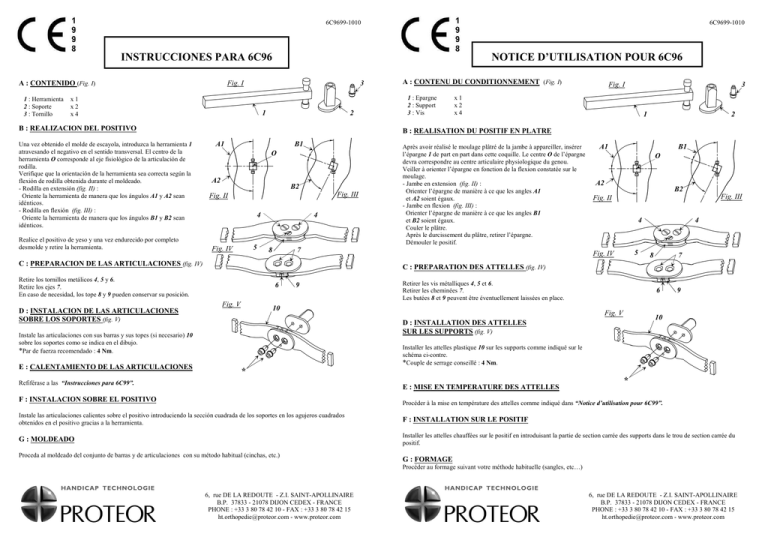
6C9699-1010 6C9699-1010 INSTRUCCIONES PARA 6C96 Fig. I A : CONTENIDO (Fig. I) 1 : Herramienta 2 : Soporte 3 : Tornillo NOTICE D’UTILISATION POUR 6C96 3 x1 x2 x4 1 2 B : REALIZACION DEL POSITIVO Una vez obtenido el molde de escayola, introduzca la herramienta 1 atravesando el negativo en el sentido transversal. El centro de la herramienta O corresponde al eje fisiológico de la articulación de rodilla. Verifique que la orientación de la herramienta sea correcta según la flexión de rodilla obtenida durante el moldeado. - Rodilla en extensión (fig. II) : Oriente la herramienta de manera que los ángulos A1 y A2 sean idénticos. - Rodilla en flexión (fig. III) : Oriente la herramienta de manera que los ángulos B1 y B2 sean idénticos. Realice el positivo de yeso y una vez endurecido por completo desmolde y retire la herramienta. 1 : Epargne 2 : Support 3 : Vis Fig. I 3 x1 x2 x4 1 2 B : REALISATION DU POSITIF EN PLATRE A1 B1 O A2 B2 Fig. III Fig. II 4 5 Fig. IV 4 8 Après avoir réalisé le moulage plâtré de la jambe à appareiller, insérer l’épargne 1 de part en part dans cette coquille. Le centre O de l’épargne devra correspondre au centre articulaire physiologique du genou. Veiller à orienter l’épargne en fonction de la flexion constatée sur le moulage. - Jambe en extension (fig. II) : Orienter l’épargne de manière à ce que les angles A1 et A2 soient égaux. - Jambe en flexion (fig. III) : Orienter l’épargne de manière à ce que les angles B1 et B2 soient égaux. Couler le plâtre. Après le durcissement du plâtre, retirer l’épargne. Démouler le positif. 7 C : PREPARACION DE LAS ARTICULACIONES (fig. IV) A1 B1 O A2 B2 Fig. III Fig. II 4 5 Fig. IV 4 8 7 C : PREPARATION DES ATTELLES (fig. IV) Retire los tornillos metálicos 4, 5 y 6. Retire los ejes 7. En caso de necesidad, los tope 8 y 9 pueden conservar su posición. 6 Fig. V 9 Retirer les vis métalliques 4, 5 et 6. Retirer les cheminées 7. Les butées 8 et 9 peuvent être éventuellement laissées en place. 10 D : INSTALACION DE LAS ARTICULACIONES SOBRE LOS SOPORTES (fig. V) 6 Fig. V 9 10 D : INSTALLATION DES ATTELLES SUR LES SUPPORTS (fig. V) Instale las articulaciones con sus barras y sus topes (si necesario) 10 sobre los soportes como se indica en el dibujo. *Par de fuerza recomendado : 4 Nm. E : CALENTAMIENTO DE LAS ARTICULACIONES A : CONTENU DU CONDITIONNEMENT (Fig. I) Installer les attelles plastique 10 sur les supports comme indiqué sur le schéma ci-contre. *Couple de serrage conseillé : 4 Nm. * Refiférase a las “Instrucciones para 6C99”. E : MISE EN TEMPERATURE DES ATTELLES F : INSTALACION SOBRE EL POSITIVO * Procéder à la mise en température des attelles comme indiqué dans “Notice d’utilisation pour 6C99”. Instale las articulaciones calientes sobre el positivo introduciendo la sección cuadrada de los soportes en los agujeros cuadrados obtenidos en el positivo gracias a la herramienta. F : INSTALLATION SUR LE POSITIF G : MOLDEADO Installer les attelles chauffées sur le positif en introduisant la partie de section carrée des supports dans le trou de section carrée du positif. Proceda al moldeado del conjunto de barras y de articulaciones con su método habitual (cinchas, etc.) G : FORMAGE Procéder au formage suivant votre méthode habituelle (sangles, etc…) 6, rue DE LA REDOUTE - Z.I. SAINT-APOLLINAIRE B.P. 37833 - 21078 DIJON CEDEX - FRANCE PHONE : +33 3 80 78 42 10 - FAX : +33 3 80 78 42 15 ht.orthopedie@proteor.com - www.proteor.com 6, rue DE LA REDOUTE - Z.I. SAINT-APOLLINAIRE B.P. 37833 - 21078 DIJON CEDEX - FRANCE PHONE : +33 3 80 78 42 10 - FAX : +33 3 80 78 42 15 ht.orthopedie@proteor.com - www.proteor.com 6C9699-1010 6C9699-1010 BEDIENUNGSANLEITUNG FÜR 6C96 6C96 INSTRUCTIONS FOR USE Fig. I A : CONTENT (Fig. I) 1 : Core 2 : Support 3 : Screw 3 x1 x2 x4 1 2 B : MAKING THE POSITIVE PLASTER CAST After making a negative plaster cast of the leg to be fitted, insert core 1 through the negative cast. The centre (O) of the core should correspond to the physiologic centre of the knee joint. Make sure the core is aligned in accordance with the flexion shown by the negative plaster cast. - Leg in extension (fig. II) : Arrange the core so that angles A1 and A2 are equal. - Leg in flexion (fig.III) : Arrange the core so that angles B1 and B2 are equal. Pour the plaster. Take out the core only when the plaster has set. Remove the positive cast. C : PREPARING THE SPLINTS (fig. IV) A1 B1 O A2 B2 Fig. III Fig. II 4 5 Fig. IV 4 8 7 6 Fig. V 9 10 Install plastic splints (10) on the supports as shown on the drawning opposite. x1 x2 x4 1 2 Das Gipsnegativ des Beines erstellen, dann den Kern 1 durch den Negativ einführen. Der Mittelpunkt O des Kerns muss dem physiologischen Mittelpunkt des Kniegelenks entsprechen. Den Kern gemäß der Flexion, die auf dem Gipsnegativ festgestellt wird, ausrichten. - Bein in Extension (Abb. II) : Der Kern muss ausgerichtet werden, so dass die Winkel A1 und A2 gleich sind. - Bein in Flexion (Abb. III) : Der Kern muss ausgerichtet werden, so dass die Winkel B1 und B2 gleich sind. Den Gips gießen. Den Gips trocknen lassen, dann den Kern entnehmen. Das Gipspositiv ausformen. A1 B1 O A2 B2 Abb. III Abb. II 4 5 Abb. IV C : VORBEREITUNG DER SCHIENEN (Ab. IV) Die Metallschrauben 4, 5 und 6 entnehmen. Die Vorrichtungen 7 entnehmen. Falls nötig können die Anschläge 8 und 9 bleiben. D : DIE SCHIENEN AUF DEN AUFLAGE EINSETZEN (Ab. V) 4 8 7 6 Abb. V 9 10 Die Kunststoffschienen 10 auf den Auflagen einsetzen, wie gezeigt in Abb. V. *Empfohlenes Drehmoment : 4 Nm. * Recommended torque value : 4 Nm. E : SOFTENING OF THE SPLINTS 1 : Kern 2 : Auflage 3 : Schraube 3 B : HERSTELLUNG DES GIPSPOSITIVS Remove metal screws 4, 5 and 6. Remove stacks 7. Stops 8 and 9 may be left in place if necessary. D : INSTALLATION OF THE SPLINTS ON THE SUPPORTS (fig. V) Abb. I A : INHALT DER VERPAKUNG (Abb. 1) * E : ERWÄRMUNG DER SCHIENEN * Soften the splints as shown in “6C99 Instructions for use”. Die Schienen erwärmen, wie gezeigt in «Bedienungsanleitung für 6C99». F : INSTALLATION ON THE POSITIVE CAST F : DIE SCHIENEN AUF DEM POSITIV EINSETZEN Install the softened splints on the positive cast, inserting the square section of the supports into the square holes of the positive cast. Die erwärmten Schienen auf dem Positiv einsetzen : den quadratischen Teil der Auflagen in die quadratischen Löcher des Positivs einführen. G : FORMING G : FORMUNG Form as usually (straps, etc…). Die Formung in gewöhnter Weise durchführen (Gurte, usw…) 6, rue DE LA REDOUTE - Z.I. SAINT-APOLLINAIRE B.P. 37833 - 21078 DIJON CEDEX - FRANCE PHONE : +33 3 80 78 42 10 - FAX : +33 3 80 78 42 15 ht.orthopedie@proteor.com - www.proteor.com 6, rue DE LA REDOUTE - Z.I. SAINT-APOLLINAIRE B.P. 37833 - 21078 DIJON CEDEX - FRANCE PHONE : +33 3 80 78 42 10 - FAX : +33 3 80 78 42 15 ht.orthopedie@proteor.com - www.proteor.com
