Diffusori ad onda Wave-Type Speaker Units Diffuseurs à onde
Anuncio
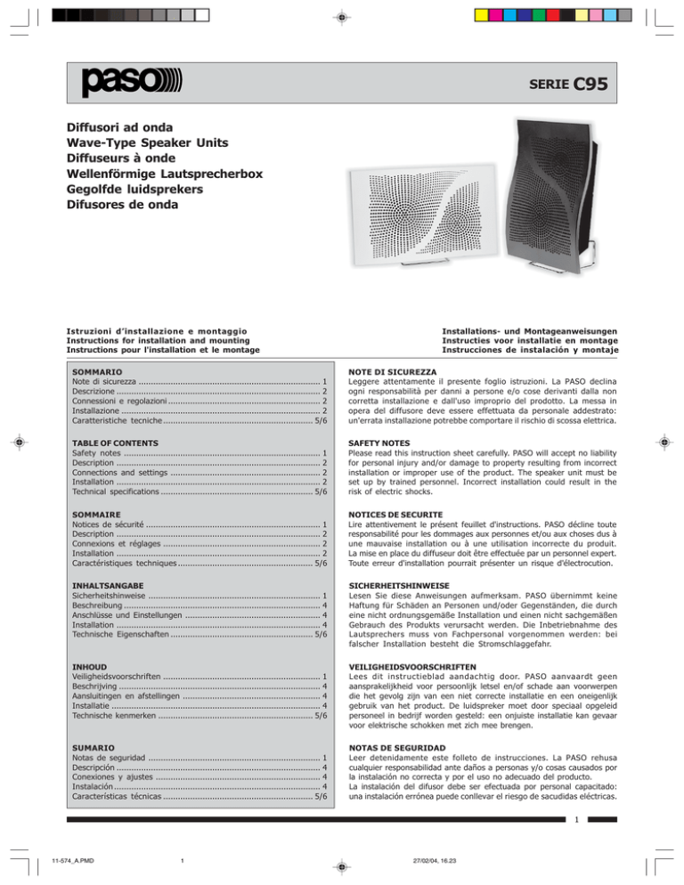
SERIE C95 Diffusori ad onda Wave-Type Speaker Units Diffuseurs à onde Wellenförmige Lautsprecherbox Gegolfde luidsprekers Difusores de onda Istruzioni dinstallazione e montaggio Instructions for installation and mounting Instructions pour l'installation et le montage Installations- und Montageanweisungen Instructies voor installatie en montage Instrucciones de instalación y montaje SOMMARIO Note di sicurezza .......................................................................... 1 Descrizione ................................................................................... 2 Connessioni e regolazioni .............................................................. 2 Installazione ................................................................................. 2 Caratteristiche tecniche ............................................................. 5/6 NOTE DI SICUREZZA Leggere attentamente il presente foglio istruzioni. La PASO declina ogni responsabilità per danni a persone e/o cose derivanti dalla non corretta installazione e dall'uso improprio del prodotto. La messa in opera del diffusore deve essere effettuata da personale addestrato: un'errata installazione potrebbe comportare il rischio di scossa elettrica. TABLE OF CONTENTS Safety notes ................................................................................ 1 Description ................................................................................... 2 Connections and settings ............................................................. 2 Installation ................................................................................... 2 Technical specifications .............................................................. 5/6 SAFETY NOTES Please read this instruction sheet carefully. PASO will accept no liability for personal injury and/or damage to property resulting from incorrect installation or improper use of the product. The speaker unit must be set up by trained personnel. Incorrect installation could result in the risk of electric shocks. SOMMAIRE Notices de sécurité ....................................................................... 1 Description ................................................................................... 2 Connexions et réglages ................................................................ 2 Installation ................................................................................... 2 Caractéristiques techniques ....................................................... 5/6 NOTICES DE SECURITE Lire attentivement le présent feuillet d'instructions. PASO décline toute responsabilité pour les dommages aux personnes et/ou aux choses dus à une mauvaise installation ou à une utilisation incorrecte du produit. La mise en place du diffuseur doit être effectuée par un personnel expert. Toute erreur d'installation pourrait présenter un risque d'électrocution. INHALTSANGABE Sicherheitshinweise ...................................................................... 1 Beschreibung ................................................................................ 4 Anschlüsse und Einstellungen ....................................................... 4 Installation ................................................................................... 4 Technische Eigenschaften .......................................................... 5/6 SICHERHEITSHINWEISE Lesen Sie diese Anweisungen aufmerksam. PASO übernimmt keine Haftung für Schäden an Personen und/oder Gegenständen, die durch eine nicht ordnungsgemäße Installation und einen nicht sachgemäßen Gebrauch des Produkts verursacht werden. Die Inbetriebnahme des Lautsprechers muss von Fachpersonal vorgenommen werden: bei falscher Installation besteht die Stromschlaggefahr. INHOUD Veiligheidsvoorschriften ................................................................ 1 Beschrijving .................................................................................. 4 Aansluitingen en afstellingen ........................................................ 4 Installatie ..................................................................................... 4 Technische kenmerken ............................................................... 5/6 VEILIGHEIDSVOORSCHRIFTEN Lees dit instructieblad aandachtig door. PASO aanvaardt geen aansprakelijkheid voor persoonlijk letsel en/of schade aan voorwerpen die het gevolg zijn van een niet correcte installatie en een oneigenlijk gebruik van het product. De luidspreker moet door speciaal opgeleid personeel in bedrijf worden gesteld: een onjuiste installatie kan gevaar voor elektrische schokken met zich mee brengen. SUMARIO Notas de seguridad ...................................................................... 1 Descripción ................................................................................... 4 Conexiones y ajustes ................................................................... 4 Instalación .................................................................................... 4 Características técnicas ............................................................. 5/6 NOTAS DE SEGURIDAD Leer detenidamente este folleto de instrucciones. La PASO rehusa cualquier responsabilidad ante daños a personas y/o cosas causados por la instalación no correcta y por el uso no adecuado del producto. La instalación del difusor debe ser efectuada por personal capacitado: una instalación errónea puede conllevar el riesgo de sacudidas eléctricas. 1 11-574_A.PMD 1 27/02/04, 16.23 SERIE C95 DESCRIZIONE I diffusori ad onda da 20W (C95/20-T e -TN) montano un altoparlante a larga banda bicono (ø 130mm), mentre i modelli da 40W sono equipaggiati con un woofer (Ø 130 mm) ed un tweeter a cupola. Le versioni (-T) sono dotate di un auto-trasformatore per il collegamento alle linee di distribuzione a tensione costante a 50, 70 e 100V. I modelli C95/40 (-N) sono invece adatti ad un collegamento a bassa impedenza (8 ohm). DESCRIPTION Each 20 W wave-type speaker unit (C95/20-T and -TN) mounts a two-cone wideband loudspeaker (ø 130 mm), while the 40 W model is equipped with a woofer (Ø 130 mm) and a dome-type tweeter. The (-T) versions are equipped with autotransformers for connection to 50, 70 and 100 V constant-voltage distribution lines. The C95/40 (-N) models, on the other hand, are suitable for low-impedance (8 ohm) connections. DESCRIPTION Les diffuseurs à onde de 20W (C95/20-T et -TN) sont munis d'un haut-parleur à large bande bicône (Ø 130 mm) alors que les modèles de 40W sont équipés d'un woofer (Ø 130 mm) et d'un tweeter à coupole. Les versions (-T) sont munies d'un autotransformateur pour la connexion aux lignes de distribution à 'tension constante' à 50, 70 et 100V. Les modèles C95/40 (-N) sont prévus pour une connexion à basse impédance (8 ohm). CONNESSIONI E REGOLAZIONI I diffusori C95 devono essere collegati tutti in derivazione alla linea di distribuzione, assicurandosi che la potenza complessiva assorbita dai diffusori non ecceda quella massima fornita dall'amplificatore (in fig. 1 è mostrato un collegamento alla linea 100V). Nel caso si volesse modificare questa impostazione, fare riferimento alla targhetta riportata in ultima pagina. CONNECTIONS AND SETTINGS The C95 speaker units must all be connected by branching to the distribution line, making sure that the overall power absorbed by the units does not exceed the maximum output provided by the amplifier (a connection to a 100 V line is shown in Fig. 1). Should it be wished to alter this set-up, refer to the label shown on the last page. CONNEXIONS ET REGLAGES Les diffuseurs C95 doivent tous être connectés en dérivation à la ligne de distribution, en s'assurant que la puissance totale absorbée par les diffuseurs n'excède pas la puissance maximum fournie par l'amplificateur (la figure 1 montre une connexion à la ligne 100V). Pour modifier cette configuration, voir la plaquette reportée à la dernière page. INSTALLAZIONE Per il fissaggio a parete od a soffitto dei diffusori C95, operare come segue: INSTALLATION To fix the C95 speaker units to a wall or ceiling, proceed as follows: INSTALLATION Pour fixer les diffuseurs C95 au mur ou au plafond, procéder comme suit: 1) prendendo come riferimento i fori (E) della piastra (D) in dotazione al diffusore, praticare due fori nella parete e fissarvi saldamente la piastra (fig. 4a). 1) Taking the holes (E) in the plate (D) supplied together with the speaker unit as references, drill two holes in the wall and use them to secure the plate firmly in place (Fig. 4a). 1) percer deux trous dans le mur en correspondance des trous (E) présents sur la plaque (D) fournie avec le diffuseur et fixer ensuite fermement la plaque au mur (fig. 4a). 2) Position the speaker unit on the tabs (F) in such a way that the recesses (C) coincide with the tabs, then slide the unit downwards so that it is supported by the tabs. 2) placer le diffuseur sur les languettes d'appui (F) en les faisant correspondre aux gorges (C), et le faire ensuite glisser vers le bas jusqu'à ce qu'il s'enclenche bien sur les languettes. 3) Tighten the screw (G) included in the supply as far as it will go to secure the speaker unit permanently to the fixing plate. 3) serrer à fond la vis (G) - fournie - pour assujettir définitivement le diffuseur à la plaque de fixation. It is also possible to position the speaker units on any top (a table, a shelf, etc.), using the specific accessory AC915 (available as an optional item). For this kind of application it is necessary to insert the support AC915 as far as it will go into the holes (A) in order to achieve horizontal positioning or into holes (B) for vertical positioning (Fig. 3a/3b). Les diffuseurs peuvent également être installés sur n'importe quelle surface (tables, étagères, etc.) en se servant de l'accessoire AC915 (optionnel) prévu à cet effet. Pour ce genre d'application, il faut insérer à fond le support AC915 dans les trous (A) - pour un positionnement horizontal - ou bien dans les trous (B) - pour un positionnement vertical (voir fig. 3a et 3b). 2) posizionare il diffusore sulle linguette dappoggio (F) facendole corrispondere alle cave (C) e farlo scorrere verso il basso fino a che risulti essere sostenuto dalle linguette stesse. 3) serrare a fondo la vite (G) - in dotazione per assicurare definitivamente il diffusore alla piastra di fissaggio. I diffusori possono inoltre essere posizionati su di un qualsiasi piano (tavoli, ripiani, etc.) utilizzando lapposito accessorio AC915 (opzionale). Per questo genere di applicazione, occorre inserire a fondo il supporto AC915 nei fori (A) - per ottenere il posizionamento orizzontale oppure nei fori (B) per quello verticale (fig. 3a/3b). + (260W) 24V – + – + – + – COM. 8 W 16 W 50V 70V 100V Fig. 1 2 11-574_A.PMD 2 27/02/04, 16.23 SERIE C95 Installazione a parete ~ Wall mounting C B E D B F A A C E (*) Fig. 4a Fig. 2 Installazione da tavolo ~ Table-top installation AC915* Fig. 3a Fig. 4b G Fig. 3b (*) opzionale - optional Fig. 4c (*) non in dotazione - not included in the supply. 3 11-574_A.PMD 3 27/02/04, 16.23 SERIE C95 BESCHREIBUNG Die geschwungenen 20W-Lautsprecherboxen (C95/20-T und -TN) sind mit einem Doppelkegel-Breitbandlautsprecher (ø 130mm) ausgerüstet; die 40 W-Modelle hingegen besitzen einen Tieftonlautsprecher (ø 130mm) und einen Kegel-Hochtonlautsprecher. Die Ausführungen (-T) besitzen einen Autotransformator für den Anschluss an die Verteilerleitungen mit konstanter Spannung mit 50, 70 und 100V. Die Versionen C95/40 (-N) sind für den Anschluss mit niedriger Impedanz (8 ohm) geeignet. BESCHRIJVING De 20W golfvormige luidsprekers (C95/20-T en -TN) zijn uitgerust met een versterker met een brede band met dubbele conus (ø 130mm), terwijl de 40W modellen zijn voorzien van een woofer (Ø 130 mm) en een koepelvormige tweeter. De (-T) versies zijn uitgerust met een autotransformator voor de aansluiting op distributielijnen op constante spanning van 50, 70 en 100V. De C95/40 (-N) modellen zijn echter geschikt voor een aansluiting met lage impedantie (8 ohm). DESCRIPCIÓN Los difusores de onda de 20W (C95/20-T y -TN) montan un altavoz bicono de banda ancha (ø 130mm), mientras que los modelos de 40W vienen equipados con un woofer (Ø 130 mm) y un tweeter de cúpula. Las versiones (-T) vienen equipadas con un auto-transformador para la conexión con líneas de distribución con 'tensión constante' de 50, 70 y 100V. Los modelos C95/40 (-N) al contrario son aptos para una conexión de baja impedancia (8 ohm). ANSCHLÜSSE UND EINSTELLUNGEN Die Lautsprecherboxen C95 müssen als Abzweigungen von der Verteilerleitung angeschlossen werden, wobei sichergestellt werden muss, dass die gesamte Leistungsaufnahme nicht die vom Verstärker gelieferte Leistung übersteigt (die Abb. 1 zeigt einen Anschluss an die 100V-Leitung). Falls Sie diese Einstellung ändern wollen, beachten Sie das auf der letzten Seite dargestellte Schild. AANSLUITINGEN EN AFSTELLINGEN Alle luidsprekers C95 moeten op een aftakking van de distributielijn worden aangesloten, waarbij moet worden verzekerd, dat het totale opgenomen vermogen van de luidsprekers niet groter is dan het maximum-vermogen dat geleverd wordt door de versterker (op afb. 1 is een aansluiting op de 100V lijn te zien). In het geval u deze instelling wilt wijzigen, dient u zich te baseren op het plaatje dat op de laatste pagina is weergegeven. CONEXIONES Y AJUSTES Los difusores C95 deben conectarse todos en derivación a la línea de distribución, comprobando que la potencia total absorbida por los difusores no supere la máxima proporcionada por el amplificador (en la fig. 1 se muestra una conexión a la línea de 100V). Si se desea modificar esta configuración, hacer referencia a la placa presentada en la última página. INSTALLATION Für die Befestigung der Lautsprecher C95 an der Wand oder Decke ist wie folgt vorzugehen: INSTALLATIE Om de luidsprekers C95 aan de wand of aan het plafond te monteren, gaat u als volgt te werk: INSTALACIÓN Para la fijación en la pared o en el techo de los difusores C95, actuar como sigue: 1) Richten Sie sich nach den Öffnungen (E) der mit dem Lautsprecher mitgelieferten Platte (D), bohren Sie zwei Löcher in die Wand und befestigen Sie die Platte sicher (Abb. 4a). 1) twee gaten in de wand boren, waarbij u de gaten (E) van de bij de luidspreker geleverde plaat (D) als referentie neemt, en hier de plaat stevig aan bevestigen(afb. 4a). 1) tomando como referencia los agujeros (E) de la placa (D) incluida en el suministro del difusor, taladrar dos agujeros en la pared y fijar firme la placa (fig. 4a). 2) Positionieren Sie den Lautsprecher auf den Haltefedern (F) und positionieren Sie ihn über den entsprechenden Öffnungen (C); lassen Sie ihn nach unten gleiten, bis er von den Federn gehalten wird. 2) de luidspreker op de draaglipjes (F) plaatsen waarbij u deze samen laat vallen met de uithollingen (C) en de luidspreker omlaag laten glijden tot hij op de lipjes rust. 2) colocar el difusor sobre las lengüetas de apoyo (F) de manera que se correspondan con las ranuras (C) y deslizarlo hacia abajo hasta que quede sostenido por las propias lengüetas. 3) Ziehen Sie die beiliegenden Schrauben (G) fest an, um den Lautsprecher definitiv an der Montageplatte zu befestigen. Die Lautsprecherboxen können auch auf einer beliebigen Ablage (Tisch, Regalböden usw.) aufgestellt werden; hierfür wird das entsprechende Zubehör AC915 (Optional) verwendet. Für diese Art von Anwendung muss die Halterung AC915 bis zum Grund in die Öffnungen (A) eingesetzt werden, wenn eine horizontale Ausrichtung gewünscht ist, oder in die Öffnungen (B), wenn eine vertikale Ausrichtung gewünscht ist (Abb. 3a/3b). 3) de bijgeleverde schroef (G) volledig aanhalen om de luidspreker definitief aan de bevestigingsplaat vast te zetten. De luidsprekers kunnen daarnaast ook op een willekeurig draagvlak worden geplaatst (tafels, planken etc.) met behulp van het speciale accessoire AC915 (optioneel). Voor dergelijke toepassingen moet de drager AC915 volledig in de gaten ( A) - voor horizontale plaatsing - of in de gaten (B) - voor verticale plaatsing worden geschoven (afb. 3a/3b). + (260W) 24V – + – + 3) apretar a fondo el tornillo (G) incluido en el suministro - para sujetar definitivamente el difusor a la placa de fijación. Los difusores también se pueden poner sobre cualquier superficie (mesas, baldas, etc.) utilizando el accesorio AC915 adecuado (en opción). Para este tipo de aplicación es preciso introducir a fondo el soporte AC915 en los agujeros (A) para conseguir la colocación horizontal - o bien en los agujeros (B) para la colocación vertical (fig. 3a/3b). – + – COM. 8 W 16 W 50V 70V 100V Abb./Afb./Fig. 1 4 11-574_A.PMD 4 27/02/04, 16.23 C95/20-T, C95/20-TN CARATTERISTICHE TECNICHE TECHNICAL SPECIFICATIONS C95/20-T (-TN) Potenza nominale Rated output power Puissance nominale Nennleistung Potencia nominal Nominaal vermogen 20 W Potenza regolabile A djustable output power Puissance réglable Einstellbare Leistung Potencia regulable Regelbaar vermogen 20W - 10W - 5W - 2,5W Risposta in frequenza Frequency response Reponse en frequence Frequenzgang Respuesta en frecuencia Frequentierespons Impedenza Impedance Impédance Impedanz Impedancia Impedantie Pressione acustica A coustic pressure Pression acoustique Schalldruck Presión acústica A koestische druk 88 dB (1W/1m) A ngolo di dispersione Dispersion angle A ngle de dispersion A usstrahlungswinkel A ngulo de dispersión Dispersiehoek 150° (@ 2 kHz) Dimensioni Dimensions Dimensions A bmessungen Medidas A fmetingen Peso Weight Poids Gewicht Peso Gewicht 125Ω - 250Ω - 500Ω 1000Ω - 2000Ω - 4000Ω 320 x 215 x 93 mm 2,1 kg Targhette potenze - Power labels ZW 125 250 500 1000 2000 4000 50V 20W 10W 5W 2,5W - - 20W 10W 5W 2,5W - 20W 10W 5W 2,5W BLU VERDE 70V 100V FILI WIRES BIANCO VIOLA 130 ÷ 20000 Hz Risposta in frequenza - Frequency response 110 GIALLO ROSSO WHITE PURPLE BLUE GREEN YELLOW 100 RED COMMON-COMUNE : BROWN- MARRONE 90 Magnitude (dB) MADE IN ITALY 5W 20W 10W FILI WIRES BIANCO VIOLA 2,5W - - 5W 2,5W - 20W 10W 5W 2,5W BLU VERDE GIALLO ROSSO WHITE PURPLE BLUE GREEN YELLOW COMMON-COMUNE : BROWN- MARRONE C95/20-TN MADE IN ITALY 70 60 50 RED 40 Frequency (Hz) Diagramma polare - Polar plot (piano orizzontale - horizontal plan) 90° 120° 60° 0 dB – 6 dB 150° 30° – 12 24 dB – 18 dB – 24 dB 2000 Hz 180° 0° 210° 330° 240° 300° 270° 5 11-574_A.PMD 5 27/02/04, 16.23 20K 10W 100V 4000 10K 20W 2000 5K 1000 2K 50V 70V 500 1K 250 500 125 200 ZW 80 100 C95/20-T C95/40-T, C95/40-TN, C95/40, C95/40-N CARATTERISTICHE TECNICHE TECHNICAL SPECIFICATIONS C95/40 (-N) C95/40-T (-TN) Potenza nominale Rated output power Puissance nominale Nennleistung Potencia nominal Nominaal vermogen Potenza regolabile A djustable output power Puissance réglable Einstellbare Leistung Potencia regulable Regelbaar vermogen Risposta in frequenza Frequency response Reponse en frequence Frequenzgang Respuesta en frecuencia Frequentierespons Impedenza Impedance Impédance Impedanz Impedancia Impedantie Pressione acustica A coustic pressure Pression acoustique Schalldruck Presión acústica A koestische druk 87 dB (1W/1m) A ngolo di dispersione Dispersion angle A ngle de dispersion A usstrahlungswinkel A ngulo de dispersión Dispersiehoek 130° (@ 2kHz) Dimensioni Dimensions Dimensions A bmessungen Medidas A fmetingen Peso Weight Poids Gewicht Peso Gewicht 40 W - 40 - 20 - 10 - 5 W 62Ω - 125Ω - 250Ω 500Ω - 1000Ω - 2000Ω 8Ω 320 x 215 x 93 mm 2,2 kg Targhette potenze - Power labels 2,8 kg Risposta in frequenza - Frequency response 110 C95/40 MADE IN ITALY 100 40W POWER RATING 8W IMPEDANCE FILI / WIRES ROSSO / RED VERDE / GREEN Magnitude (dB) 90 80 70 60 20W 100V FILI WIRES BIANCO VIOLA 5W - - 10W 5W - 10W 5W 40W 20W BLU VERDE GIALLO ROSSO WHITE PURPLE BLUE GREEN YELLOW RED 50 40 Frequency (Hz) COMMON-COMUNE : BROWN- MARRONE C95/40-T MADE IN ITALY Diagramma polare - Polar plot (piano orizzontale - horizontal plan) 90° 120° 60° 0 dB – 6 dB 150° 30° – 12 24 dB – 18 dB – 24 dB 2000 Hz 180° 0° 210° 330° 240° 300° 270° 6 11-574_A.PMD 6 27/02/04, 16.23 20K 10W 40W 10K 20W 2000 5K 40W 70V 1000 2K 50V 500 1K 250 500 125 200 62 100 ZW PASO S.p.A Via Mecenate, 90 - 20138 MILANO - ITALIA - TEL. +39-02-580 77 1 (15 linee r.a.) - FAX +39-02-580 77 277 - http://www.paso.it - Printed in Italy - 02/04 - 1K - 11/574-A 100 ÷ 20000 Hz
