Tema 3: Memoria cache Summary of memory technology
Anuncio
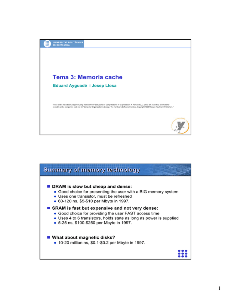
Tema 3: Memoria cache
Eduard Ayguadé i Josep Llosa
These slides have been prepared using material from “Estructura de Computadores II” by professors A. Fernandez, J. Llosa & F. Sanchez and material
available at the companion web site for “Computer Organization & Design. The Hardware/Software Interface. Copyright 1998 Morgan Kaufmann Publishers.”
Summary of memory technology
DRAM is slow but cheap and dense:
z
z
z
Good choice for presenting the user with a BIG memory system
Uses one transistor, must be refreshed
60-120 ns, $5-$10 per Mbyte in 1997.
SRAM is fast but expensive and not very dense:
z
z
z
Good choice for providing the user FAST access time
Uses 4 to 6 transistors, holds state as long as power is supplied
5-25 ns, $100-$250 per Mbyte in 1997.
What about magnetic disks?
z
10-20 million ns, $0.1-$0.2 per Mbyte in 1997.
1
Processor - DRAM gap
Processor - memory performance gap:
z
grows 50% per year
Performance
1000
CPU
µProc
60%/yr.
100
10
DRAM
7%/yr.
DRAM
2000
1999
1997
1998
1996
1994
1995
1992
1993
1991
1990
1989
1987
1988
1986
1985
1984
1982
1983
1981
1980
1
Time
Processor - DRAM gap
Is this gap so important?
z
A lot of work can be done inside the processor during a memory
access
Example:
z
z
z
DRAM latency of 80 ns
Processor clock cycle of 1 ns
80 clks to access data x 6 instructions per clk → or 480
instructions
2
Motivation for memory hierarchy
Goal:
z
z
Present the user with large amounts of memory using the
cheapest technology.
Provide access at the speed offered by the fastest technology.
CPU
Level 1
Levels in the
memory hierarchy
Increasing distance
from the CPU in
access time
Level 2
Level n
Size of the memory at each level
Motivation for memory hierarchy
3
Locality
A principle that makes having a memory hierarchy a good
idea
If an item is referenced,
z
z
it will tend to be referenced again soon (temporal locality)
nearby items will tend to be referenced soon (spatial locality).
Examples:
z
z
90/10 rule: 90% of the dynamic references to code are located in
10% of the memory address space (loops, procedures, …)
Access to consecutive elements in data structures (vectors,
arrays, lists, …)
Locality
Temporal locality suggests:
z
“Once you reference a memory location, bring its contents to a
level closer to the processor”
Spatial locality suggests:
z
“Once you reference a memory location, also bring the contents of
nearby memory locations”
Block or Line:
z
z
z
A number of consecutive words in memory (e.g. 32 bytes,
equivalent to 4 words x 8 bytes)
Unit of information that can either be present or not present in a
level of the memory hierarchy
Unit of information that is transferred between two levels in the
hierarchy
4
Block or line
Finding a piece of data in memory ...
11
3
2
processor @
line in memory
byte inside word
word inside line
1 line
Example:
- 1 word contains 8 bytes = 64 bits
- 1 line contains 4 words
- memory contains 2048 lines
Block or line
Memory hierarchy is inclusive
Main memory
0
1
block x exists in both levels
block y exists only in the upper level
N-1
line
Cache
0
1
M-1
word
Processor
5
Line size trade-off
In general, larger line sizes take advantage of spatial
locality, BUT:
z
z
z
Larger line size means larger miss penalty: takes longer time to fill
up the line
If line size is too big relative to cache size, miss rate will go up: too
few cache lines
Pollution: with big lines you bring data with less probability of
being used (spatial locality)
Memory hierarchy terminology
Hit: data appears in some block in a level of the hierarchy
z
z
Hit rate (h): the fraction of memory access found in that level
Hit time th: time to access that level: memory access time + time
to determine hit/miss
Miss: data needs to be retrieved from a block in the next
level of the hierarchy
z
z
Miss rate m = 1 - h
Miss penalty (tm)= time to replace a block in that level with a block
in the next level
In general, Average Access Time = th x h + tm x m
6
Instruction and data caches
Instructions and data
behave in a different way
Harward architecture that
allows simultaneous access
to both I and D
Combined L2, usually
L2>>L1
Impact on performance
Suppose a processor executes at
z
z
z
Clock Rate = 1 GHz (1 ns per cycle)
CPI = 1.3
50% arith/logic, 30% ld/st, 20% control
Suppose a 1% instruction miss rate with 50 cycle miss
penalty:
z
z
CPI = ideal CPI + stalls per instruction = 1.3 + 0.01x50 = 1.9
31 % of the time waiting for instructions!
Suppose a 10% data miss rate with 50 cycle miss penalty:
z
z
CPI = ideal CPI + average stalls per instruction =
1.3 + (0.30x0.10x50) = 2.8 cycles
53 % of the time the processor is stalled waiting for memory!
7
More on memory hierarchy terminology
Mapping policy:
z
z
Where a line can be found?
Direct, Set associative, Fully associative
Replacement policy:
z
When a level is full, which line is eliminated in order to have an
empty slot for the new line?(temporal locality: the new one has higher
z
Random, FIFO, LRU
probability of being referenced in the near future)
Write policy:
z
z
Which levels in the hierarchy are updated on a write?
On hit: Write through, copy back. On miss: write allocate, write no
allocate
Mapping policy
Where a line can be found in cache memory?
000
001
010
011
100
101
110
111
000
001
010
011
100
101
110
111
00 0
00 1
01 0
01 1
10 0
10 1
11 0
11 1
data
data
data
data
data
data
data
data
data
data
data
data
data
data
data
data
data
data
data
data
data
data
data
data
00000
00001
00010
00011
00100
00101
00110
00111
01000
01001
01010
01011
01100
01101
01110
01111
10000
10001
10010
10011
10100
10101
10110
10111
11000
11001
11010
11011
11100
11101
11110
11111
data
data
data
data
data
data
data
data
data
data
data
data
data
data
data
data
data
data
data
data
data
data
data
data
data
data
data
data
data
data
data
data
Main memory
Direct cache
Fully associative
cache
2-way set
associative cache
8
tag
tag
tag
tag
tag
tag
tag
tag
data
data
data
data
data
data
data
data
000
001
010
011
100
101
110
111
00000
00001
00010
00011
00100
00101
00110
00111
01000
01001
01010
01011
01100
01101
01110
01111
10000
10001
10010
10011
10100
10101
10110
10111
11000
11001
11010
11011
11100
11101
11110
11111
data
data
data
data
data
data
data
data
data
data
data
data
data
data
data
data
data
data
data
data
data
data
data
data
data
data
data
data
data
data
data
data
tag
tag
tag
tag
tag
tag
tag
tag
data
data
data
data
data
data
data
data
000
001
010
011
100
101
110
111
00000
00001
00010
00011
00100
00101
00110
00111
01000
01001
01010
01011
01100
01101
01110
01111
10000
10001
10010
10011
10100
10101
10110
10111
11000
11001
11010
11011
11100
11101
11110
11111
data
data
data
data
data
data
data
data
data
data
data
data
data
data
data
data
data
data
data
data
data
data
data
data
data
data
data
data
data
data
data
data
Mapping policy
How can one differenciate between the possible candidates
for a cache line?
Main memory
In cache line number 010 one can find:
tag = 00 → line 00010 of main memory
tag = 01 → line 01010 of main memory
tag = 10 → line 10010 of main memory
tag = 11 → line 11010 of main memory
Direct cache
Mapping policy
How can one differenciate between the possible candidates
for a cache line?
Main memory
In cache line number 010 one can find:
tag = 00000 → line 00000 of main memory
tag = 00001 → line 00001 of main memory
…
tag = 11111 → line 00001 of main memory
Fully associative
9
tag
tag
tag
tag
tag
tag
tag
tag
data
data
data
data
data
data
data
data
00 0
00 1
01 0
01 1
10 0
10 1
11 0
11 1
00000
00001
00010
00011
00100
00101
00110
00111
01000
01001
01010
01011
01100
01101
01110
01111
10000
10001
10010
10011
10100
10101
10110
10111
11000
11001
11010
11011
11100
11101
11110
11111
data
data
data
data
data
data
data
data
data
data
data
data
data
data
data
data
data
data
data
data
data
data
data
data
data
data
data
data
data
data
data
data
Mapping policy
How can one differenciate between the possible candidates
for a cache line?
Main memory
Direct mapping
In cache line number 010 one can find:
tag = 000 → line 00001 of main memory
tag = 001 → line 00101 of main memory
…
tag = 111 → line 11101 of main memory
Set associative
Implementing the mapping policy
tag
# line
Line size = 1 word x 4 bytes
10
Implementing the mapping policy
Direct mapping: four-word lines (32 bit per word)
tag
# line
Data
Implementing the mapping policy
Fully associative
tag
11
Implementing the mapping policy
# set
4-way set associative
tag
Sources of cache misses
Compulsory (cold start or process migration, first
reference): first access to a block
z
“Cold” fact of life: not a whole lot you can do about it
Conflict (collision): Multiple memory locations mapped to
the same cache location
z
z
Solution 1: increase cache size
Solution 2: increase associativity
Capacity: Cache cannot contain all blocks accessed by the
program
z
Solution: increase cache size
Invalidation: other process (e.g., I/O) updates memory
12
Sources of cache misses
Mapping policies behaviour:
Reducing misses
Assist cache:
z Bring line into cache if it shows
locality, thus avoiding the
replacement of other lines with
more locality
cache
cache
AC
AC
main
main
memory
memory
Victim cache:
z Give a second opportunity to
those lines that are replaced
cache
cache
VC
VC
main
main
memory
memory
13
0
8 Mbytes
4 Mbytes
2 Mbytes
1 Mbyte
512 Kbytes
256 Kbytes
128 Kbytes
30
64 Kbytes
40
8 Mbytes
4 Mbytes
2 Mbytes
1 Mbyte
512 Kbytes
256 Kbytes
128 Kbytes
64 Kbytes
32 Kbytes
2-way
16 Kbytes
1-way
50
32 Kbytes
50
8 Kbytes
60
16 Kbytes
60
8 Kbytes
4 Kbytes
2 Kbytes
40
4 Kbytes
2 Kbytes
1 Kbyte
0
1 Kbyte
ns
ns
Evaluation: access time (th)
0.8µ technology
80
70
4-way
30
8-way
20
10
Evaluation: access time (th)
0.8µ technology
70
16 bytes
32 bytes
64 bytes
128 bytes
256 bytes
20
10
direct mapped
14
Evaluation: miss rate
data cache only
SPEC95, reference data set
1012 instructions simulated
nr = 0.3735 references to memory per instruction
0.40
1-way
0.35
2-way
0.30
4-way
0.25
8-way
0.20
0.15
0.10
8 Mbytes
4 Mbytes
2 Mbytes
1 Mbyte
512 Kbytes
256 Kbytes
128 Kbytes
64 Kbytes
32 Kbytes
16 Kbytes
8 Kbytes
4 Kbytes
2 Kbytes
0.00
1 Kbyte
0.05
Evaluation: miss rate
data cache only
SPEC95, reference data set
1012 instructions simulated
nr = 0.3735 references to memory per instruction
0.50
0.45
16 bytes
32 bytes
0.40
64 bytes
0.35
128 bytes
0.30
256 bytes
0.25
0.20
0.15
0.10
0.05
8 Mbytes
4 Mbytes
2 Mbytes
1 Mbyte
512 Kbytes
256 Kbytes
128 Kbytes
64 Kbytes
32 Kbytes
16 Kbytes
8 Kbytes
4 Kbytes
2 Kbytes
1 Kbyte
0.00
direct mapped
15
Evaluation: average memory access
0.8µ technology
DRAM access time 250 ns
data cache only
write through / write allocate
8-byte bus between MC and MP
SPEC95, reference data set
1012 instructions simulated
nr = 0.3735 references to memory per instruction
120
1-way
100
2-way
4-way
ns
80
8-way
60
40
8 Mbytes
4 Mbytes
2 Mbytes
1 Mbyte
512 Kbytes
256 Kbytes
128 Kbytes
64 Kbytes
32 Kbytes
16 Kbytes
8 Kbytes
4 Kbytes
2 Kbytes
0
1 Kbyte
20
Evaluation: average memory access
0.8µ technology
DRAM access time 250 ns
data cache only
write through / write allocate
8-byte bus between MC and MP
SPEC95, reference data set
1012 instructions simulated
nr = 0.3735 references to memory per instruction
250
16 bytes
32 bytes
200
64 bytes
128 bytes
150
ns
256 bytes
100
8Mbytes
4Mbytes
2Mbytes
1 Mbyte
512Kbytes
256Kbytes
128Kbytes
64Kbytes
32Kbytes
16Kbytes
8Kbytes
4Kbytes
2Kbytes
0
1Kbyte
50
16
Cache line replacement policy
Random Replacement:
z
z
Hardware randomly selects a cache line out of the set and
replaces it
Can be implemented with a single counter.
First-In First-Out (FIFO):
z
z
The oldest one in the set is going to be replaced
Can be implemented with a counter per set, assuming that lines in
the set are filled/replaced in order.
Cache line replacement policy
Least Recently Used (LRU):
z
z
z
z
Hardware keeps track of the access history
Replace the entry that has not been used for the longest time
For two-way set associative cache one needs one bit for LRU
replacement
Exercise: how to implement it?
17
Cache write policy
Cache read is much easier to handle than cache write:
z
Instruction cache is much easier to design than data cache
Cache write policy:
z
It decides how do we keep data in the cache and memory
consistent
Two options on a hit:
z
Copy-back: write to cache only. Write the cache block to memory
when that cache block is being replaced on a cache miss.
9 Need a “dirty bit” for each cache block
9 Greatly reduce the memory bandwidth requirement
z
Write-through: write to cache and memory at the same time.
9 Replacements do not need to write lines back to memory
9 So … writes are done with a large access time!
Write buffer for write-through policy
A Write Buffer is needed between the cache and main
memory
z
z
Processor: writes data into the cache and the write buffer
Cache controller: write contents of the buffer to memory
Write buffer is just a FIFO:
z
Typical number of entries: 4
processor
cache
cache
main
main memory
memory
word
18
Write buffer for copy-back policy
Reducing miss penalty: in this case the buffer holds those
replaced “dirty” lines that need to be updated in main
memory
tags
=
=
=
=
=
=
=
=
=
hit in write buffer
@ issued
by processor
cache
cache
main
main memory
memory
lines
mux
On a miss, now we need to check if the line is in the write
buffer
Cache write policy (cont.)
What happens on a write miss? Do we read in the block?
z
z
Yes: Write-allocate
No: Write-no-allocate
Usually:
z
z
Write-allocate goes together with copy-back
Write-no-allocate goes together with write-through
19
Moving lines around …
Size of the bus between cache and main memory:
Moving lines around …
Single module memory / one-word wide bus
b0
memory access
b1
b2
b3
transfer +
cache load
Multi module memory / one-line wide bus
b0-b3
Multi module memory / one-word wide bus
b0
b1
b2
b3
20
Moving lines around …
Interleaved memory
0
8
16
1
9
17
2
10
18
3
11
4
12
5
13
6
14
7
15
count % 8
# line
b0
access
b1
b2
b3
b4
b5
b6
b7
transfer
Memorias de Semiconductores
Tipos de Memoria de Semiconductores:
Memoria Estática (SRAM, Static RAM). Cada celda de memoria equivale a 1
biestable (7-8 transistores). En comparación con las DRAM son rápidas, tienen
un alto consumo, poca capacidad y son caras.
→ Memoria Cache
Memoria Dinámica (DRAM, Dynamic RAM). Cada celda se comporta como un
condensador (1-1.x transistores). En comparación con las SRAM son lentas,
tienen un bajo consumo, mucha capacidad y son baratas. Problema del
refresco.
→ Memoria Principal
21
Memorias de Semiconductores
Celda SRAM de 6 Transistores
wordline
bitline’
bitline
La información se almacena en 2 inversores acoplados.
Al activar la word line el dato almacenado se lee a través de las
bit lines.
Se obtiene el dato negado y sin negar.
Memorias de Semiconductores
Celda SRAM de 6 Transistores
bitline’
bitline
22
Memorias de Semiconductores
Celda DRAM de 1 Transistor
wordline
bitline
La información se almacena en el condensador Cs.
Al activar la word line el dato almacenado se lee a través de la bitline.
El condensador se va descargando poco a poco, es necesario recargarlo
regularmente (refresco).
Estructura interna de una DRAM
20 bits
@
FILA
COLUMNA
Matriz de Memoria
1024 x 1024 x 1 bit
@FILA
10
Decodificador de fila
210 columnas
celda
.
wordline
.
.
.
.
.
.
.
210 filas
bitline
wordline
. . . . . .
. . .
Amplificadores de señal
@COLUMNA
10
Decodificador de columna
R/W
DATO
bitline
23
Estructura interna de una DRAM
Una operación de lectura:
@FILA
Decodificador de fila
1) Decodificar @FILA, se activa la señal wordline
.
wordline
.
.
.
.
.
.
.
. . . . . .
. . .
Amplificadores de señal
Decodificador de columna
R/W
Estructura interna de una DRAM
Una operación de lectura:
2) Se accede a todas las celdas de la fila, los datos de toda la fila se
envían a los amplificadores de señal y se recupera la tensión (el dato
está en un condensador que se va descargando poco a poco).
wordline
...
bitline
bitline
bitline
wordline
...
bitline
bitline
bitline
24
Estructura interna de una DRAM
Una operación de lectura:
@FILA
Decodificador de fila
2) Se accede a todas las celdas de la fila, los datos de toda la fila se
envían a los amplificadores de señal y se recupera la tensión.
.
.
.
.
.
.
.
.
. . . . . .
. . .
Amplificadores de señal
Decodificador de columna
R/W
Estructura interna de una DRAM
Una operación de lectura:
@FILA
Decodificador de fila
2) Se accede a todas las celdas de la fila, los datos de toda la fila se
envían a los amplificadores de señal y se recupera la tensión.
.
.
.
.
.
.
.
.
. . . . . .
. . .
Amplificadores de señal
Decodificador de columna
R/W
25
Estructura interna de una DRAM
Una operación de lectura:
3) Decodificar @COLUMNA, se selecciona una bitline y se envía el dato al
Decodificador de fila
exterior a través del buffer R/W.
.
.
.
.
.
.
.
.
Amplificadores de señal
@COLUMNA
Decodificador de columna
R/W
DATO
Estructura interna de una DRAM
Una operación de lectura:
@FILA
Decodificador de fila
4) La lectura es destructiva, hay que reescribir la celda (y toda la fila) para
recuperar el valor original (equivale a precargar la fila para el siguiente
acceso a memoria).
.
.
.
.
.
.
.
.
. . . . . .
. . .
Amplificadores de señal
Decodificador de columna
R/W
26
Estructura interna de una DRAM
Una operación de escritura:
Decodificador de fila
3) Prácticamente igual, la única diferencia es que la celda se reescribe con
el dato que entra por el buffer R/W.
.
.
.
.
.
.
.
.
Amplificadores de señal
@COLUMNA
Decodificador de columna
R/W
DATO
Estructura interna de una DRAM
Una operación de escritura:
@FILA
Decodificador de fila
4) Hay que reescribir la celda con el nuevo valor (y el resto de la fila
con el valor original).
.
.
.
.
.
.
.
.
. . . . . .
. . .
Amplificadores de señal
Decodificador de columna
R/W
27
Estructura interna de una DRAM
Una operación de lectura. Resumen:
1) Decodificar @FILA, se activa la señal wordline
2) Se accede a todas las celdas de la fila, los datos de toda la fila se envían a los
amplificadores de señal y se recupera la tensión (el dato está en un
condensador que se va descargando poco a poco).
3) Decodificar @COLUMNA, se selecciona una bitline y se envía el dato al
exterior a través del buffer R/W.
4) La lectura es destructiva, hay que reescribir la celda (y toda la fila) para
recuperar el valor original (equivale a precargar la fila para el siguiente acceso
a memoria).
Una operación de escritura:
3) Prácticamente igual, la única diferencia es que la celda se reescribe con el dato
que entra por el buffer R/W.
4) Hay que reescribir la celda con el nuevo valor (y el resto de la fila con el valor
original).
Estructura interna de una DRAM
Cronograma simplificado de una operación de lectura
tRC
A
@FIL
@COL
@FIL
D
@COL
DATA
tRAC
1
2
tCAC
3
4
3 Valores fundamentales:
Tiempo de acceso (tRAC): retardo máximo desde que se suministra la dirección de fila hasta
que se obtiene el dato → latencia de memoria.
Tiempo de ciclo (tRC): intervalo de tiempo mínimo entre dos accesos consecutivos a memoria
→ ancho de banda.
Tiempo de acceso a columna (tCAC): retardo máximo desde que se suministra la dirección de
columna hasta que se obtiene el dato.
28
Estructura interna de una DRAM
Cronograma simplificado de una operación de lectura
tRC
A
@FIL
@COL
@FIL
D
@COL
DATA
tRAC
1
tCAC
2
3
4
Valores típicos:
Tiempo de acceso (tRAC): 50ns.
Tiempo de ciclo (tRC): 70ns.
Tiempo de acceso a columna (tCAC): 20ns.
¿Posibles Mejoras? → Acceso a Bloques de Información.
Aprovechando que los datos de la fila están en los amplificadores de señal, sólo es
necesario enviar la @COL+1, @COL+2, …
FPM DRAM (Fast Page Mode DRAM)
Idea Fundamental: una vez accedida la fila, se puede acceder a
varias columnas simplemente cambiando la @COL.
→ Aprovechamos la localidad espacial
tPC
A
@FIL
@COL
@COL
D
DATA
tRAC
tCAC
DATA
tCAC
Valores típicos:
z
z
1er acceso (tRAC): 50ns.
2o acceso (tPC): 35ns.
29
Tipos de DRAM
Fast Page Mode DRAM (FPM DRAM)
Extended Data Out DRAM (EDO DRAM)
Burst EDO DRAM (BEDO DRAM)
Synchronous DRAM (SDRAM)
Double Data Rate SDRAM (DDR SDRAM)
DDR2 SDRAM
Evaluación FPM DRAM
Leer un bloque de 32 bytes (suponiendo que la MP está 8 entrelazada):
z
z
z
z
Placa Base de 66MHz (tiempo de ciclo:15ns).
4 Accesos a Memoria.
Temporización: 5-3-3-3 (incluye precarga).
Ancho de Banda: 152 Mbytes/s.
tPC
A
@FIL
@COL
@COL
D
DATA
tRAC
tCAC
DATA
tCAC
Problemas de la FPM DRAM: hay que esperar a que el dato sea leído antes de enviar la
nueva @COL.
30
EDO DRAM (Extended Data Out DRAM)
Idea Fundamental: se añade un registro en la salida de datos
→ se puede solapar el acceso a los datos
→ con el envío de la nueva @COL
tPC
A
@FIL
@COL
@COL
D
DATA
DATA
tRAC
Valores típicos:
z
z
1er acceso (tRAC): 50ns.
2o acceso (tPC): 20ns.
Estructura interna de una EDO DRAM
20 bits
@
FILA
COLUMNA
Matriz de Memoria
1024 x 1024 x 1 bit
@FILA
10
Decodificador de fila
210 columnas
celda
.
wordline
.
.
.
.
.
.
.
210 filas
bitline
. . . . . .
. . .
Amplificadores de señal
@COLUMNA
10
Decodificador de columna
R/W
REG
DATO
31
Evaluación EDO DRAM
Leer un bloque de 32 bytes:
z
z
z
z
Placa Base de 66MHz (tiempo de ciclo:15ns).
4 Accesos a Memoria.
Temporización: 5-2-2-2 (incluye precarga).
Ancho de Banda: 193 Mbytes/s.
tPC
A
@FIL
@COL
D
@COL
DATA
DATA
tRAC
Posibles mejoras de la EDO DRAM: Los accesos siempre son a posiciones
consecutivas.
BEDO DRAM (Burst EDO DRAM)
Idea Fundamental: añadir un contador para generar la nueva @COL.
tPC
A
@FIL
@COL
D
DATA
DATA
tRAC
Valores típicos:
z
z
1er acceso (tRAC): 50ns.
2o acceso (tPC): 15ns.
32
Estructura interna de una BEDO DRAM
20 bits
@
FILA
COLUMNA
Matriz de Memoria
1024 x 1024 x 1 bit
@FILA
10
Decodificador de fila
210 columnas
celda
.
wordline
.
.
.
.
.
.
.
210 filas
bitline
. . . . . .
. . .
Amplificadores de señal
@COLUMNA
10
CONT
10
Decodificador de columna
R/W
REG
DATO
Evaluación BEDO DRAM
Leer un bloque de 32 bytes:
z
z
z
z
Placa Base de 66MHz (tiempo de ciclo:15ns).
4 Accesos a Memoria.
Temporización: 5-1-1-1 (incluye precarga).
Ancho de Banda: 266 Mbytes/s.
tPC
A
@FIL
@COL
D
DATA
DATA
tRAC
Problema: Es una memoria asíncrona. Las memorias asíncronas son difíciles de mejorar
por problemas de ruido. Es muy difícil que soporten frecuencias superiores a los 66MHz.
33
Solución Arquitectónica
Problema: las memorias asíncronas no se pueden mejorar.
Solución Arquitectónica:
z Segmentar el funcionamiento interno de las memorias
z Hacer que funcionen de forma SÍNCRONA.
→ Desaparecen los problemas de ruido
→ Se puede aumentar la frecuencia de funcionamiento
SDRAM (Synchronous DRAM)
Funcionamiento segmentado.
Síncrona.
Puede funcionar a mucha más frecuencia que una DRAM asíncrona.
Autoincremento de la @COL.
Programable vía comandos.
Dispone de múltiples bancos (permite ocultar la precarga).
El funcionamiento interno es muy similar a una DRAM asíncrona.
34
DDR SDRAM (Double Data Rate SDRAM)
Es una SDRAM que envía los datos a doble velocidad que una SDRAM convencional.
CLOCK
SDRAM
DDR SDRAM
DATA
DATA
DATA
DATA
DATA DATA DATA DATA
Modificando exclusivamente la circuitería encargada de la entrada/salida de datos se
dobla el ancho de banda.
La latencia de memoria es prácticamente la misma.
DDR2 SDRAM
Es una DDR mejorada en los siguientes aspectos:
z Reducción del tamaño de página (número de columnas del array):
9 Reduce el tiempo de acceso
9 Reduce el consumo de energía
z Aumenta el número de bancos
9 Aumenta las posibilidades de solapar, con un buen controlador de memoria,
la precarga y el acceso a fila de bancos independientes.
z Aumento de la frecuencia
35
Tipos de DRAM
Ejemplos de Memorias DRAM comerciales
Año
Tipo Memoria
Latencia
Frec. Placa
Base
1r dato / resto
64 Mbits
66 MHz
50 / 20 ns
203.4 Mbytes/s
Capacidad
Ancho Banda lect.
32bytes
2000
EDO DRAM
2002
SDRAM
128 Mbits
167 MHz
36 / 6 ns
565.1 Mbytes/s
2003
DDR SDRAM
256 Mbits
200 MHz
30 /2.5 ns
813.8 Mbytes/s
Memoria Entrelazada
Memoria Principal 8-entrelazada de 256 Mbytes
Líneas 32 bytes
LÍNEA 0
Espacio
Lógico
0
1
M0
M1
2
0
1
2
…
7
3
8
9
10
…
15
4
16
17
18
…
23
24
25
26
…
31
…
…
…
228-1
32MB
256MB
M2
…
…
…
228-8
228-7
228-6
M7
8 bytes
228-1
1 byte
36
Memoria Entrelazada
Memoria Principal 8-entrelazada de 256 Mbytes
Chip DRAM
con 4 bancos
DIMM con 8 chips de Memoria DRAM
M0
M1
M2
1
2
…
7
0
8
9
10
…
15
16
17
18
…
23
24
25
26
…
31
…
…
…
…
…
228-8
228-7
228-6
…
228-1
32MB
0
8
16
…
8MB
226+0
226+8
226+16
…
8MB
227+0
227+8
227+16
…
8MB
227+226+0
227+226+8
227+226+16
…
8MB
M7
8 bytes
M0 M1 M2 M3
M4 M5 M6 M7
1 byte
Memoria Entrelazada
M0 M1 M2 M3 M4 M5 M6 M7
Banco 0
Banco i
8
8
8
8
8
8
8
8
Bus 64 bits
64
B0
M0
B1
B2
M0 M1 M2 M3
M4 M5 M6 M7
B3
37
Memoria Entrelazada
Memoria Principal 8-entrelazada de 256 Mbytes
Cada banco contiene 4 bytes de cada línea de 32 bytes
DRAM con 4 bancos
0
8
16
…
8MB
226+0
226+8
226+16
…
8MB
227+0
227+8
227+16
…
8MB
227+226+0
227+226+8
227+226+16
…
Estructura de un banco de 8 MB
0
8
16 24
…
8K
1KB
8MB
8 celdas de 1 bit
1 byte
Memoria Entrelazada
Memoria Principal 8-entrelazada de 256 Mbytes
Distribución de los 4 bytes de cada línea dentro de un módulo DRAM
DRAM con 4 bancos
0
8
16
…
8MB
226+0
226+8
226+16
…
8MB
8K
línea 0
línea 1
línea 2
línea 256
línea 257
línea 258
…
…
línea 255
…
línea 220-1
línea 511
…
227+0
227+8
227+16
…
227+226+0
227+226+8
227+226+16
…
8MB
8MB
1KB
1 byte
38
Memoria Entrelazada
Memoria Principal 8-entrelazada de 256 Mbytes
Líneas de 32 bytes
¿Dónde está el byte 000204Eh?
0000000000000010000001001110
línea 258
byte 14
0000000000000010000001001110
banco 0
fila 1
columna 9
módulo 6
Memoria Entrelazada
0000000000000010000001001110
banco 0
fila 1
columna 9
módulo 6
0
banco 0
8
24
…
8MB
fila 1
226+0
banco 1
226+8
226+24
…
línea 1
línea 2
línea 257
línea 258
…
…
línea 255
línea 511
8MB
banco 0
227+0
banco 2
línea 0
línea 256
227+8
227+24
…
8MB
8K
columna 9
227+226+0
banco 3
227+226+8
227+226+24
…
1 byte
M0 M1 M2 M3
8MB
¡Byte 000204Eh!
módulo 6
M4 M5 M6 M7
…
línea 220-1
1KB
39
Memoria Entrelazada
La transmisión de datos entre MP y MC se hace por líneas completas
Es preciso cambiar la dirección de acceso, para acceder al primer byte de la línea
Se accede simultáneamente a todos los módulos
0000000000000010000001001110
línea 258
byte 14
0000000000000010000001001110
banco 0
fila 1
columna 9
módulo 6
0 0 0 0 0 0 0 0 0 0 0 0 0 0 1 0 0 0 0 0 0 1 000XXX
banco 0
fila 1
columna 8
Todos los
módulos
Memoria entrelazada
Queremos montar 1 GByte de memoria RAM usando módulos DIMM de 256
Mbytes.
z
z
z
z
z
z
z
La dirección tiene 30 bits
Necesitamos 4 módulos DIMM
Cada uno de los módulos se direcciona con 28 bits
Todos los módulos están físicamente conectados al mismo bus de datos
(triestados)
Sólo uno de los módulos puede funcionar en cada momento
Los dos bits de mayor peso de la dirección determinan cuál de los
módulos funciona (CS)
Los 28 bits restantes determinan cómo se accede al módulo
40
Memoria entrelazada
Queremos montar 1 GByte de memoria RAM usando módulos DIMM de 256
Mbytes.
Ejemplo: Acceso a la dirección 2000204Eh
Entrelazado
“vertical”
Entrelazado
“horizontal”
100000000000000010000001001110
fila 1
banco 0
columna 9
módulo 6
DIMM 2
Memoria Entrelazada
Memoria Principal 8-entrelazada de 256 Mbytes
Líneas de 32 bytes
z
0
8
¿Cómo queda distribuida la línea 0 en los chips de Memoria?
16 24 32 40
M0
…
1
9
17 25 33 41
M1
…
2
10 18 26 34 42
M2
…
7
...
15 23 31 39 47
…
M7
Ejemplo: Lectura de una línea de 32 bytes
LÍNEA 0
41
Memoria Entrelazada
Memoria Principal de 256 Mbytes
z
0
8
¿Cómo queda la línea 0 distribuida físicamente en Memoria?
16 24 32 40
…
1
9
17 25 33 41
…
2
10 18 26 34 42
M1
M0
…
M2
7
15 23 31 39 47
…
M7
...
Ejemplo: Lectura de una línea de 32 bytes
LÍNEA 0
Memoria Entrelazada
Memoria Principal de 256 Mbytes
z
0
8
¿Cómo se lee la línea 0 de MP?
16 24 32 40
M0
…
1
9
17 25 33 41
…
2
10 18 26 34 42
M1
…
M2
Enviar / decodificar la @fila (fila 0)
Leer la fila y enviarla a los amplificadores de señal
7
...
15 23 31 39 47
…
M7
42
Memoria Entrelazada
Memoria Principal de 256 Mbytes
z
¿Cómo se lee la línea 0 de MP?
M1
M0
0
8
16 24 32 40
…
1
9
M2
17 25 33 41
…
2
10 18 26 34 42
M7
...
…
Enviar / decodificar la @fila (fila 0)
Leer la fila y enviarla a los amplificadores de señal
7
15 23 31 39 47
…
Memoria Entrelazada
Memoria Principal de 256 Mbytes
z
¿Cómo se lee la línea 0 de MP?
M1
M0
0
8
16 24 32 40
…
1
9
M2
17 25 33 41
0
1
…
2
10 18 26 34 42
2
M7
…
7
15 23 31 39 47
…
7
a Memoria Cache
Enviar/ decodificar la @col (col 0)
Leer el 1er dato de la línea en todos los módulos
Enviar los primeros 8 bytes a la MC
43
Memoria Entrelazada
Memoria Principal de 256 Mbytes
¿Cómo se lee la línea 0 de MP?
z
M1
M0
0
8
16 24 32 40
…
1
9
M2
17 25 33 41
8
9
…
2
10 18 26 34 42
10
M7
…
7
15 23 31 39 47
…
15
a Memoria Cache
Incrementar la @col (col=1)
Leer el 2o dato de la línea en todos los módulos
Enviar los siguientes 8 bytes a la MC
...
Memoria Entrelazada
Lectura de 1 línea de 32 bytes, la MP está organizada en DIMMs de 8 bytes de
ancho.
z
Cronograma Simplificado:
9 Latencia fila (4 ciclos), latencia columna (4 ciclos), velocidad transferencia
(8 bytes por ciclo)
@FIL
@COL
datos datos datos datos
z
La velocidad de salida / transferencia de los datos dependerá del tipo
de Memoria y de la placa base (buses)
44
Memoria Entrelazada
Escritura de 1 línea de 32 bytes, la MP está organizada en DIMMs de 8 bytes
de ancho.
z
Cronograma Simplificado:
9 Latencia fila (4 ciclos), latencia columna (4 ciclos), velocidad transferencia
(8 bytes por ciclo)
@FIL
@COL
datos datos datos datos
z
¡El cronograma es idéntico!
Memoria Entrelazada
Ejemplo de cronograma de transferencia de una línea entre
Memoria Principal y Memoria Cache:
z
z
z
z
z
z
z
Tamaño de línea: 8 bytes.
Latencia de fila: 3 ciclos.
Latencia de columna: 2 ciclos.
Memoria Principal organizada en “DIMMs” de 2 bytes de ancho
Velocidad de transferencia entre MP y MC: 2 bytes por ciclo
Memoria cache tarda 1 ciclo en detectar miss (se requiere transferencia
de 1 línea desde MP)
Memoria cache tarda 1 ciclo en escribir la línea recibida y enviar el dato
al procesador (hit)
45
Memoria Entrelazada
Acceso en fallo
Petición
CPU
Lectura
MP
M
Acceso en acierto
Lectura de línea de MP
lat. F.
H
lat. C. 0,1 2,3 4,5 6,7
11 ciclos
Reducing miss penalty
Load into cache as words are transferred:
tm
@ CPU
Write to MP
read from MP
Load into MC
Write-buffer for copy-back
tm
@ CPU
Write to MP
read from MP
Load into MC
46
Reducing miss penalty
Early restart:
tm
@ CPU
Write to MP
b0
b1
b2
b3
b2 b3
b0
b1
read from MP
Load into MC
Reorder data:
tm
@ CPU
Write to MP
read from MP
Load into MC
Lab session
Code 1: Matrix product, different ijk forms
#define N 256
main() {
int i, j, k;
float A[N][N], B[N][N], C[N][N];
/* initialization of A, B and C*/
for (i=0; i<N; i++)
for (j=0; j<N; j++) {
A[i][j] = 1.2;
B[i][j] = 3.4;
C[i][j] = 0.0;
}
/* Computation of C */
for (i=0; i<N; i++)
for (j=0; j<N; j++)
for (k=0; k<N; k++)
C[i][j] = C[i][j] + A[i][k] * B[k][j];
}
47
Lab session
Code 1: Matrix product, different ijk forms
Cycles
Instructions executed
Floating point operations
Memory accesses (read and write)
Instruction cache misses
Data cache misses
Time (seconds)
MIPS
MFLOPS
ijk form
ikj form
jki form
1.392.048.480
1.082.413.938
1.846.706.514
959.064.862
959.064.702
959.067.394
33.555.463
33.555.463
33.555.463
655.615.970
655.613.221
655.617.326
2.571
2.384
2.537
17.086.764
2.321.923
33.757.489
6,971
5,412
9,234
137,58
177,21
103,86
4,81
6,20
3,63
Data cache miss ratio
2,606%
0,354%
5,149%
Instruction cache miss ratio
0,000%
0,000%
0,000%
Note: execution on a Pentium MMX at 200 MHz
Lab session
Code 1: Matrix product using scalar temporal variable
#define N 256
main() {
int i, j, k;
float t, A[N][N], B[N][N], C[N][N];
/* initialization of A, B and C*/
for (i=0; i<N; i++)
for (j=0; j<N; j++) {
A[i][j] = 1.2;
B[i][j] = 3.4;
C[i][j] = 0.0;
}
/* Computation of C */
for (i=0; i<N; i++)
for (j=0; j<N; j++) {
t = C[i][j];
for (k=0; k<N; k++)
t = t + A[i][k] * B[k][j];
C[i][j] = t;
}
}
48
Lab session
Code 1: Matrix product using scalar temporal variable
ijk form
ikj form
jki form
Cycles
874.348.935
762.446.346
1.531.322.928
Instructions executed
389.753.758
590.490.215
590.492.384
33.554.463
33.554.463
33.554.463
186.374.856
320.329.494
320.333.194
Floating point operations
Memory accesses (read and write)
Instruction cache misses
Data cache misses
Time (seconds)
MIPS
MFLOPS
2.366
2.290
2.723
17.192.127
2.317.923
33.821.126
4,372
3,812
7,657
89,148
154,903
77,118
7,675
8,802
4,382
Data cache miss ratio
9,224%
0,724%
10,558%
Instruction cache miss ratio
0,000%
0,000%
0,000%
Note: execution on a Pentium MMX at 200 MHz
Lab session
Questions:
z
z
Why the ikj is the best form?
In the second version using a scalar temporal variable:
9 Why the miss ratio grows if the number of misses is smaller?
9 Why the execution time is better if the miss ratio is higher
9 Why the MIPS metric is worse if the execution time is better?
49
Lab session
Code 2:
#define ITER 1000000
#define N 128*1024
#define mask N-1
main() {
int i, j, stride;
float v[N];
/* float = 4 bytes */
for (stride=1; stride<16; stride++) {
for (i=0; i<N; i++)
v[i]=1.3;
misses();
i=0;
for(j=0; j<ITER; j++){
v[i]=v[i]+11.2;
i = (i+stride) & mask;
}
printf(“%d: %d\n”, stride, misses());
}
}
Lab session
Code 2: execution on a Pentium MMX at 200 MHz
1200000
num. of misses
1000000
800000
600000
400000
200000
0
1
2
3
4
5
6
7
8
9 10 11 12 13 14 15
stride
What can you guess from this plot?
50
Lab session
Code 3:
#define ITER 1000000
#define N 16*1024
main() {
int i, j, stride;
float v[N];
/* float = 4 bytes */
stride = 8;
for (j=256; j<=N; j=j+256) {
for (i=0; i<N; i++)
v[i]=1.3;
misses();
k=0;
for (i=0; i<ITER; i++) {
v[k] = v[k] + 1.1;
k = k+stride;
if (k >=j) k=0;
}
printf("%d: %d\n", j*4, misses());
}
}
Lab session
Code 3: execution on a Pentium MMX at 200 MHz
1200000
num. of misses
1000000
800000
600000
400000
200000
0
0
4
8
12
16
20
24
28
32
j x 4 (K)
What can you guess from this plot?
51
