Relés Instantáneos Instantaneous Relays
Anuncio
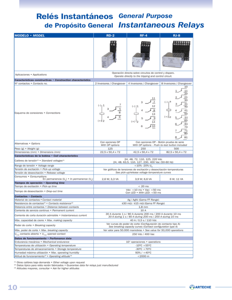
Relés Instantáneos General Purpose de Propósito General Instantaneous Relays MODELO • MODEL RD-2 RJ-8 Operación directa sobre circuitos de control y disparo. Operate directly to the tripping and control circuit. Aplicaciones • Applications Características constructivas • Construction characteristics Nº contactos • Contacts no. RF-4 2 Inversores / Changeover 4 Inversores / Changeover 8 Inversores / Changeover 10 1 3 7 (–) 1 3 5 8 4 6 Esquema de conexiones • Connections (+) 2 11 7 2 (–) a 12 (–) 1 4 8 13 5 9 (+) 2 (+) d 14 6 3 31 40 4 41 50 5 51 60 61 70 71 80 6 10 7 8 Alternativas • Options Peso (g) • Weight (g) Dimensiones (mm) • Dimensions (mm) Características de la bobina • Coil characteristics Calibres de tensión(1) • Standard voltages(1) Rango de tensión • Voltage range Tensión de excitación • Pick-up voltage Tensión de desexcitación • Release voltage Consumos • Consumptions En permanencia (UN) • In permanence (UN) Con opciones OP With OP options 125 22,5 x 50,4 x 72 Ver gráficos de tensiones de excitación y desexcitación-temperaturas See pick-up/release voltage-temperature curves 2,6 W; 3,3 VA Contactos • Contacts Material de contactos • Contact material Resistencia de contactos(2) • Contacts resistance(2) Distancia entre contactos • Distance between contacts Corriente de servicio continuo • Permanent current Corriente de corta duración admisible • Instantaneous current Máx. capacidad de cierre • Max. making capacity Poder de corte • Breaking capacity Máx. poder de corte • Max. breaking capacity Umax contacto abierto • Umax opened contact Otros calibres bajo demanda • Other voltage upon request Datos típico para relés recién fabricados • Guarantee data for relays just manufactured (3) Altitudes mayores, consultar • Ask for higher altitudes (2) 10 6 W; 11 VA Ag / AgNi (Gama FF Range) ≤30 mΩ / ≤15 mΩ (Gama FF Range) 1,8 mm 10 A 30 A durante 1 s / 80 A durante 200 ms / 200 A durante 10 ms 30 A during 1 s / 80 A during 200 ms / 200 A during 10 ms 40 A / 0,5 s / 110 Vdc Ver curvas de poder de corte (Configuración de contacto tipo A) See breaking capacity curves (Contact configuration type A) Ver valor para 50.000 maniobras • See value for 50,000 operations Datos de funcionamiento • Perfomance data Endurancia mecánica • Mechanical endurance Temperaturas de utilización • Operating temperature Temperaturas de almacenamiento • Storage temperature Humedad máxima utilización • Max. operating humidity Altitud de funcionamiento(3) • Operating altitude(3) (1) 3,9 W; 6,6 VA < 20 ms Vdc: <10 ms • Vac: <50 ms Con LED • With LED: <50 ms Tiempo de desexcitación • Drop-out time 81 Con opciones OP - Botón prueba de serie With OP options - Push-to-test button included 250 500 42,5 x 50,4 x 72 82,5 x 50,4 x 72 24, 48, 72, 110, 125, 220 Vdc 24, 48, 63,5, 110, 127, 230, 400 Vac (50-60 Hz) +10% -20% UN Tiempos de operación • Operating time Tiempo de excitación • Pick-up time 11 20 21 30 250 Vdc / 400 Vac 107 operaciones • operations -10ºC +55ºC -30ºC +70ºC 93% / +40ºC <2000 m RelsAux(esp-eng)A4 30/10/09 13:47 P gina 6 C M Y CM Relés Monoestables Nº contactos No. contacts 2 4 8 16 Model RD-2 RF-4 RJ-8 RI-16 CY CMY K Auxiliary Relays Relés Auxiliares Modelo MY Instantaneous Relays MODELO • MODEL RD-2 • RF-4 • RJ-8 X X XX X Tensión•Voltage Vcc•Vdc OP Vca•Vac TIPO • TYPE Standard Rápido • Fast-acting Diodo en paralelo con la bobina (solo Vcc) Diode in parallel with the coil (only Vdc) Con características sísmicas • Seismic characteristics Características sísmicas y diodo en paralelo con la bobina (solo Vcc) Seismic characteristics and diode in parallel with the coil (only Vdc) R DI SY SYDI OPCIONES • OPTIONS SOPLADO MAGNETICO (Para aumentar el poder de corte) MAGNETIC ARC BLOW OUT (To increase breaking capacity) LED FRONTAL FRONT LED INDICACION MECANICA DE LA POSICION DE LOS CONTACTOS CONTACT POSITION MECHANICAL INDICATOR BANDEROLA DE DISPARO Y ACTUACION DEL RELE RELAY TRIP FLAG BOTON DE PRUEBA PUSH-TO-TEST BUTTON No Si • Yes No Si • Yes No Si • Yes No Si • Yes No Mueve los contactos To push the contacts Enclava los contactos Fix the contacts 0 1 0 1 0 1 0 1 0 1 2 RD-2 RF-4 RJ-8 RI-16 7 5 8 6 11 7 12 8 13 9 14 10 10 11 20 21 30 31 40 41 50 51 60 61 70 71 80 81 10 11 20 21 30 31 40 41 50 51 60 61 70 71 80 81 Bornas A Terminals 3 4 3 2 (+) 1 (-) 4 5 6 1 2 3 2 (+) 1 (-) 4 5 6 7 8 2 3 4 5 6 7 8 10 11 20 21 30 31 40 41 50 51 60 61 70 71 80 81 a (+) d (-) Bornas B Terminals 1 2 3 4 5 Relés Biestables 6 7 8 a (+) d (-) Latching Relays Opciones • Options Nº Modelo contactos Rápido Diodo Varistancia No. Fast Diode Model Varistor contacts [] BF-3 3 [] [] [] BF-4 4 [] [] [] BJ-8 8 [] [] [] BI-16 16 BF-3 2 (+) BF-4 1 (-) I 11 7 12 8 13 9 1 (+) [] [] [] [] [] [] [] [] [] BJ-8 BI-16 d (+) c (-) I 10 11 20 21 30 31 40 41 50 51 60 61 70 71 80 81 I 2 Botón Indicador mecánico de test de actuación Test Mechanical button indicator Rango extendido de tensión Extended voltage range 10 11 20 21 30 31 40 41 50 51 60 61 70 71 80 81 Bornas A Terminals 1 11 7 12 8 13 9 14 10 2 3 4 5 6 7 8 10 11 20 21 30 31 40 41 50 51 60 61 70 71 80 81 3 14 (+) 4 II 5 10 (-) 1 3 B1 (+) 4 5 II 6 2 3 b (+) 4 5 II 6 a (-) 7 8 Bornas B Terminals 1 2 3 b (+) 6 Composici n 4 5 II 6 a (-) 7 8
