ESPECIFICACIONES TÉCNICAS TECHNICAL SPECIFICATION
Anuncio
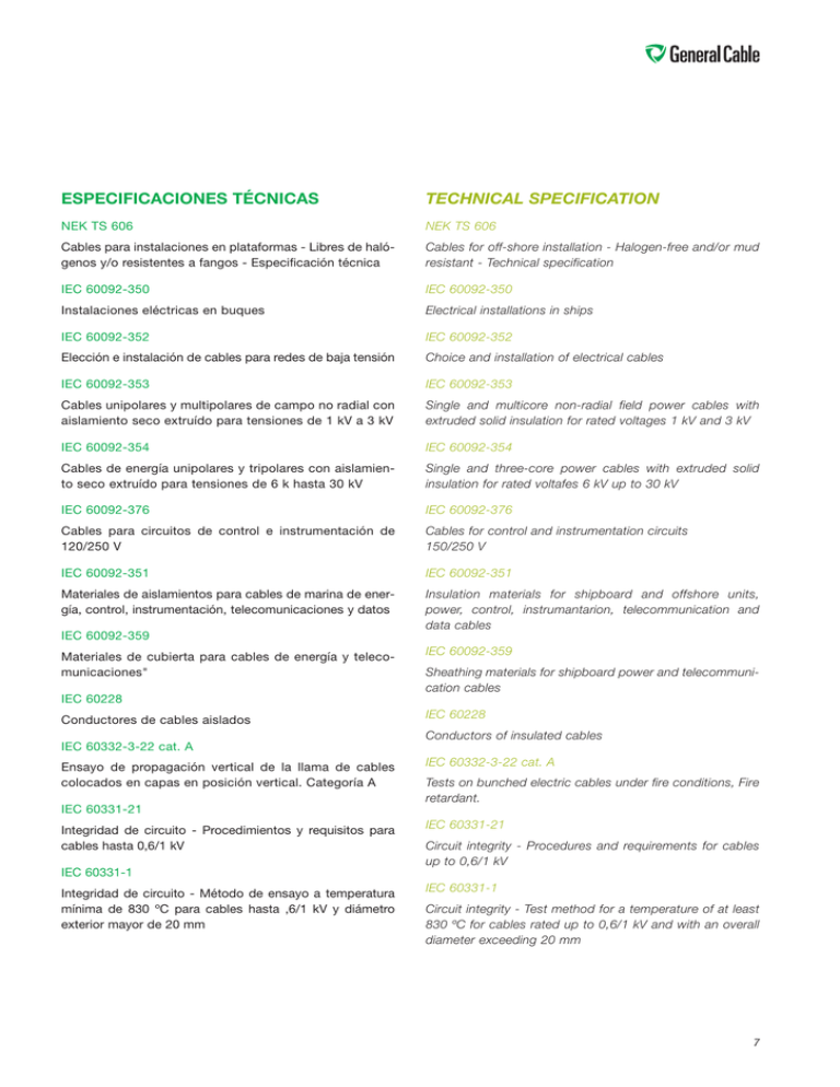
ESPECIFICACIONES TÉCNICAS TECHNICAL SPECIFICATION NEK TS 606 NEK TS 606 Cables para instalaciones en plataformas - Libres de halógenos y/o resistentes a fangos - Especificación técnica Cables for off-shore installation - Halogen-free and/or mud resistant - Technical specification IEC 60092-350 IEC 60092-350 Instalaciones eléctricas en buques Electrical installations in ships IEC 60092-352 IEC 60092-352 Elección e instalación de cables para redes de baja tensión Choice and installation of electrical cables IEC 60092-353 IEC 60092-353 Cables unipolares y multipolares de campo no radial con aislamiento seco extruído para tensiones de 1 kV a 3 kV Single and multicore non-radial field power cables with extruded solid insulation for rated voltages 1 kV and 3 kV IEC 60092-354 IEC 60092-354 Cables de energía unipolares y tripolares con aislamiento seco extruído para tensiones de 6 k hasta 30 kV Single and three-core power cables with extruded solid insulation for rated voltafes 6 kV up to 30 kV IEC 60092-376 IEC 60092-376 Cables para circuitos de control e instrumentación de 120/250 V Cables for control and instrumentation circuits 150/250 V IEC 60092-351 IEC 60092-351 Materiales de aislamientos para cables de marina de energía, control, instrumentación, telecomunicaciones y datos Insulation materials for shipboard and offshore units, power, control, instrumantarion, telecommunication and data cables IEC 60092-359 Materiales de cubierta para cables de energía y telecomunicaciones" IEC 60092-359 Sheathing materials for shipboard power and telecommunication cables IEC 60228 Conductores de cables aislados IEC 60228 Conductors of insulated cables IEC 60332-3-22 cat. A Ensayo de propagación vertical de la llama de cables colocados en capas en posición vertical. Categoría A IEC 60332-3-22 cat. A Tests on bunched electric cables under fire conditions, Fire retardant. IEC 60331-21 Integridad de circuito - Procedimientos y requisitos para cables hasta 0,6/1 kV IEC 60331-21 Circuit integrity - Procedures and requirements for cables up to 0,6/1 kV IEC 60331-1 Integridad de circuito - Método de ensayo a temperatura mínima de 830 ºC para cables hasta ,6/1 kV y diámetro exterior mayor de 20 mm IEC 60331-1 Circuit integrity - Test method for a temperature of at least 830 ºC for cables rated up to 0,6/1 kV and with an overall diameter exceeding 20 mm 7 IEC 60331-2 IEC 60331-2 Integridad de circuito - Método de ensayo a temperatura mínima de 830 ºC para cables hasta ,6/1 kV y diámetro exterior no mayor de 20 mm Circuit integrity - Test method for a temperature of at least 830 ºC for cables rated up to 0,6/1 kV and with an overall diameter not exceeding 20 mm IEC 60754-1 IEC 60754-1 Ensayos de los gases desprendidos durante la combustión de materiales procedentes de los cables Determination of the amount of halogen acid gas IEC 60764-2 IEC 60754-2 Determinación del grado de acidez de gases de los materiales por medida del pH y la conductividad Determination of degree of acidity of gases IEC 61034-2 IEC 61034-2 Medida de la densidad de los humos emitidos por cables en combustión bajo condiciones definidas Measurement of smoke density Los cables del presente catálogo estan amparados con Aprobaciones de Tipo de las principales sociedades de Clasificación: 8 Cables shown in this cataloge are covered with “Type Approvals” from main classification societies: ABS BUREAU VERITAS DET NORSKE VERITAS LLOYD’S REGISTER R.I.N.A. GERMANISCHER LLOYD APLICACIONES APLICATIONS En función de su utilización, los cables se distribuyen en los siguientes grupos: Depending on their use, the cables are distributed into the following groups: CABLES DE ENERGÍA DE BAJA TENSIÓN (NEK TS 606) LOW VOLTAGE POWER CABLES (NEK TS 606) - Tensión asignada 0,6/1 kV. - - Composiciones hasta 4 conductores. Identificación por coloración del aislamiento. Power cables suitable for operation at up to and including 0.6/1 kV. - Sin armar y armados con trenza de hilos de cobre estañado. Constructions up to and including 4 core. Coloured core identification. - Diseños disponibles para resistencia a los fangos y/o resistencia al fuego (integridad de circuito). Non armoured and armoured with tinned copper wire braid. - Diseños disponibles para variadores de frecuencia (VFD). Available designs with mud resistance and/or fire resistance (circuit integrity). - Available designs for variable frequency drives (VFD). - CABLES DE ENERGÍA DE MEDIA TENSIÓN (NEK TS 606) MEDIUM VOLTAGE CABLES (NEK TS 606) - - Tensiones asignadas de 3,6/6 kV a 12/20 kV. - Armados con trenza de hilos de cobre estañado. - - Diseños disponibles para resistencia a los fangos. - Cables for distribution of energy in voltages of 3,6/6 to 12/20 kV. Armoured with tinned copper wire braid. Available designs with mud resistance. CABLES DE CONTROL (NEK TS 606) CONTROL CABLES (NEK TS 606) - Tensión asignada 0,6/1 kV. - - Composición de 2 a 37 conductores. Identificación por numeración. - Armados con trenza de hilos de cobre estañado. - - - Diseños disponibles para resistencia a los fangos y/o resistencia al fuego (integridad de circuito). Available from 2 to 37 cores. Identification by numbering. Armoured with tinned copper wire braid. Available designs with mud resistance and/or fire resistance (circuit integrity). CABLES DE INSTRUMENTACIÓN (NEK TS 606) INTRUMENTATION CABLES (NEK TS 606) - Cables de pares o tríos de tensión asignada 150/250 V. - Multiunit (pairs or triple core) - Conductores identificados por color y cinta numerada en cada par. - Cores identified by colours and numbered tape in each unit. - Cable de dos pares sin pantalla individual, tiene formación de cuadrete / estrella - Two pair cable without individual screen has a star/quad composition. - Apantallado colectivo (trenza de cobre estañado) o individual y colectiva (cinta Cu / poliéster y drenaje en cada par y trenza de cobre estañado colectiva). - Collective screening (tinned copper braid) or individual and collective (Cu/polyester tape and drain wire in each unit and collective tinned copper braid., 9 COMPOSICIÓN CONSTRUCTION En base a las normas IEC citadas anteriormente, y haciendo un repaso a la formación de los cables tenemos: On the basis of the above-mentioned IEC standards, and reviewing the formation of the cables, we have: Conductor Conductor De cobre recocido estañado según IEC 60092-350: Tinned annealed copper in accordance with IEC 60092350: Clase 2: Conductores rígidos de formación 7 hilos (en secciones pequeñas) o coronas concéntricas para secciones mayores. Class 2: Rigid conductors with 7 wire formation (in small sections) or concentric layers in big cross sections. Clase 5: Conductores flexibles de formación multifilar. Class 5: Flexible conductors bunched or multibunched configurations. En general se utilizan los de clase 2, pero está aumentando el uso de los de clase 5 por su manejabilidad y por tanto mayor facilidad de instalación. El conductor se utiliza estañado para dar una mayor protección de las conexiones frente a las oxidaciones en los ambiente marinos duros. Para secciones y composiciones normalizadas a utilizar, ver cuadros siguientes: In general those class 2 are used, but the use of class 5 is growing, due to their handeability and therefore their greater ease of installation. Tin plated conductor is used to offer greater protection of conections against oxidation in heavy marine environments. See the following tables for standarized sections and compositions to be used: Secciones / Cross sectional area Tipo cable Tensión Sección conductor Norma IEC Cable type Voltage kV Area of conductor mm2 IEC Standard Baja Tensión 1 kV 1,5 ÷ 300 mm2 Power Low Voltage 3 kV 10 ÷ 300 mm2 60092-353 Instrumentation 250 V 0,50 ÷ 2,50 60092-376 Media Tensión 6 kV 10 ÷ 630 mm2 Power Medium Voltage 10 kV 16 ÷ 630 mm2 15 kV 25 ÷ 630 mm2 20 kV 35 ÷ 630 mm Instrumentación 10 2 60092-354 Composición nº conductores / Composition number of cores Tipo cable Cable type Número de conductores Number of cores B.T. “N” (No se fijan) Power L.V. “N” (Not specified) Cables de control 2,4,7,12,19,27,37 conductores Control cables 2,4,7,12,19,27,37 cores Instrumentación 1,2*, 4,7,10,14,19,24,30,37 pares Instrumentation 1,2*, 4,7,10,14,19,24,30,37 pairs M.T. 1 ÷ 3 conductores Power M.V. 1 ÷ 3 cores Norma IEC IEC Standard 60092-353 60092-376 60092-376 60092-354 (*) El cable de dos pares tiene una formación de cuadrete/estrella, utilizándose los conductores diametralmente opuestos para formar los dos pares. (*) Two pair cable is a star-quad composition, cores diametrally oposed are used to conform the pairs. Materiales de aislamiento Insulation materials NEK TS 606 especifica los materiales de aislamiento haciendo referencia a la norma IEC 60092-351. Los utilizados en los cables de este catálogo son: NEK TS 606 specifies insulation materials making reference to standard IEC 60092-351. The ones used in the current catalog are: EPR (Etileno propileno). Elastómero termoestable, deformación casi nula por la acción del calor. Confiere mayor flexibilidad al cable. Especialmente indicado si la cubierta debe ser de compuesto termoestable. EPR (Ethylene propylene). A thermosetting elastomer, it has an almost nil distortion due to the action of heat. It gives the cable greater flexibility. Especially suitable if the sheath has to be a crosslinked compound. HEPR (Etileno propileno de alto módulo libre de halógenos). Variante de compuesto de EPR que ofrece unas mejores propiedades eléctricas y mecánicas. Esta mejora se refleja en su equiparamiento dimensional con el polietileno reticulado. HEPR (Hard grade etylene propylene.) Improved EPR compound bringing beter performance both in mechanical o electrical properties. This brings to a thickness insulations similars to the XLPE ones. 11 Materiales de aislamiento Tipo de compuesto de aislamiento Designación abreviada Máxima temperatura Conductor °C Operación Normal Cortocircuito EPR 90 250 HEPR 90 250 Elástométrico o termoestable Etileno propileno o similar (EPM o EPDM) libre de halógenos Etileno propileno de alto módulo o alto grado libre de halógenos Insulation materials Type of insulating compound Abbreviated designation Maximum rated conductor Temperature °C Normal Operation Short-circuit EPR 90 250 HEPR 90 250 Elastomeric or thermoset: Ethylene-propylene rubber or similar (EPM o EPDM) Halogen free High modulus of hard grade halogen free ethylene propylene rubber 12 Materiales de cubierta Sheathing materials Las cubiertas de los cables protegen al conjunto de los conductores aislados de las agresiones mecánicas o ambientales que puedan sufrir. Las agresiones mecánicas son principalmente abrasiones por arrastre en los conductos y se producen durante la instalación, mientras que las ambientales (calor, presencia de aceites o agentes agresivos) afectarán al cable durante toda su vida útil. The sheath of the cables protects the set of cores from the mechanical or environmental aggressions they can suffer. Mechanical aggressions are mainly abrasions from the dragging of the cables and tears at angles of the tubes and occur during the installation, while the environment aggressions (heat, presence of oils or aggressive agents) will affect the cable throughout its working life. Compuesto termoestable libre de halógenos SHF 2. Tiene las ventajas de ser un termoestable que no desprende gases tóxicos ni humos opacos (ver anexo 2), junto a una buena resistencia a los aceites, combustibles y disolventes. Buena resistencia a solicitudes mecánicas. Halogen free termosetting compound SHF 2. It has the advantages of being a heat-stable compound which does not release toxic gases or opaques smoke in case of fire (see annex 2), and it has good resistance to oils, fuel and solvents. Good resistance to mechanical demands. 12 Compuesto termoestable libre de halógenos y resistente a fangos SHF Mud. Halogen-free mud-resistant crosslinked compound SHF Mud. Idénticas características del materila tipo SHF 2 añadiendo la resistencia a fangos según se define en NEK TS 606. The same characteristics as per material type SHF 2 adding mud resistance according to NEK TS 606. Materiales de cubierta Sheathing materials Tipo de material de cubierta Designación Abreviada Elastomérico o termoestable Libre de halógenos Abbreviated designation Elastomeric or thermosetting SHF 2 Libre de halógenos y resistente a fangos Type of sheathing compound SHF Mud Halogen free SHF 2 Halogen free & mud resistant SHF Mud Armaduras Armouring Las armaduras aportan protección mecánica al cable. Utilizándose en este caso el cobre en versión estañada. The armour gives the cable mechanical protection. The copper in tinplated version being used in this case. La utilización de cobre estañado en la armadura ejerce una doble función ya que se comporta como armadura pero también como pantalla. The use of tinned copper in the armour performs a dual function as it behaves as armour but also as a screen. Armaduras Armouring materials Tipo Materiales Type Materials TRENZA - Cobre recocido estañado BRAID - Tinned annealed copper 13 Pantallas Screening En los cables de baja tensión, las pantallas son los elementos que aportan protección al cable frente a los campos eléctricos y electromagnéticos de alta frecuencia. Es un elemento especialmente indicado para cables de instrumentación, control y transmisión de señales por su sensibilidad a las radiaciones que pueden distorsionar la señal transmitida por el cable. Para proteger el cable de las radiaciones hay que apantallar el conjunto de los conductores (protección de perturbaciones exteriores) o cada uno de los pares o tríos (campos electromagnéticos provinientes de otros elementos del mismo cable). In low tensión cables, the screens are the elements which provide the cable protection against electromagnetic fields. This is an element especially suitable for cables for instrumentation, control and transmission of signals thanks to its sensitivity to radiation which can distort the signal transmitted by the cable. To protect the cable from radiation it is necessary to screen the group of conductors (protection from external disturbance) or each one of the pairs or triples (electromagnetic fields from other elements of the same cable). Según la norma, las pantallas pueden ser de trenza de cobre o bien de cinta de poliéster. En todos los diseños de 2, 3 y 4 fases, la sección de la pantalla está definida según los criterios de la norma IEC 60092-352 Table 2 y por lo tanto puede ser utilizada como conductor de protección. En los cables que requieren armadura, la utilización de armadura de trenza de cobre estañado hace que estando debidamente colocadas a tierra, pueda ser utilizada para también como pantalla del cable. According to the standard, screens can be either braid or laminated polyester tape. In all designs of 2, 3 and 4 cores, the screen cross-section has been defined according to the criteria set in standard IEC 60092-352 Table 2, so it can be used as an earthing conductor. In armoured type cables, the use of tinned copper wire braid armour, when properly earthed, allows to use it as a collective screen. Pantallas / Screening materials Tipo Type Materiales Materials - Cobre recocido estañado - Tinned annealed copper - Cu/poliéster - Cu/polyester TRENZA BRAID CINTA TAPE Compatibilidad Electromagnética (EMC) Electromagnetic compatibility (EMC) Los productos de General Cable cumplen los requerimientos sobre Compatibilidad Electromagnética siempre que en su instalación se hayan respetado las condiciones establecidas en la norma IEC 60533. When General Cable products are installed in accordance with IEC 60533, they fulfil the requirements for ElectroMagnetic Compatibility. 14 COMPORTAMIENTO DE LOS CABLES EN CASO DE FUEGO FIRE PERFORMANCE OF CABLES A fin de determinar el comportamiento de los cables ante una situación de incendio, se han desarrollado una serie de normas que definen unas condiciones de fuego y miden el comportamiento del cable en una situación similar a la de instalación, sin embargo, debe tenerse en cuenta que estos ensayos establecen unas condiciones fijas y reproducibles y sirven para valorar el comportamiento de los cables en dicha situación. To establish how cables perform in the event of fire, a series of standards have been developed to define fire conditions and measure the cable’s performance in a similar situation to that of the installation. It should nonetheless be remembered that these tests establish fixed, reproducible conditions used to appraise the performance of the cables in this situation. La normativa IEC actual contempla los siguientes casos: Current IEC standards envisage the following events: - No propagación de la llama (Norma IEC 60332-1-2). - Non-flame propagation (IEC 60332-1-2). Una llama de potencia 1 kW en contacto con la cubierta del cable durante un tiempo establecido en la norma no debe provocar su propagación. Así se evita que el cable sea origen de un incendio ocasionado por un incidente de menor entidad o una fuente de calor externa que accidentalmente entre en contacto con el mismo. A 1-kW flame in contact with the cable sheath for a time established in the standard should not spread. The cable will not therefore prompt a fire caused by a minor incident or by an external heat source with which it comes into accidental contact. - No propagación del incendio (Norma IEC 60332-3-22) - Non-fire propagation (IEC 60332-3-22) Un incendio ajeno al cable puede afectar una canalización, agravándose si está en posición vertical que permita circulación de aire creando así el llamado efecto chimenea. Si se alcanza la temperatura de descomposición de los materiales orgánicos, se produce una combustión exotérmica de los cables y la consiguiente propagación del incendio. Los compuestos de aislamiento y cubierta de los cables Exzhellent-Mar, se formulan de tal forma que dificulten dicha reacción exotérmica. Para simular dicha situación, la prueba consiste en la aplicación de un quemador de gas de 20 kW de potencia a un mazo de cables dispuestos de tal forma que reproducen una canalización vertical con aire forzado. En estas condiciones, el incendio provocado en A fire unconnected with the cable may affect a wiring system and become more serious if the system is oriented vertically, thus allowing the circulation of air and the creation of a chimney effect. If the decomposition temperature of the organic materials is reached, exothermic combustion of the cables occurs and the fire spreads. The insulation compounds used in Exzhellent-Mar cable sheaths are designed to hinder exothermic reaction. To simulate this situation, the test involves the application of powered air and a 20-kW gas burner to a bundle of cables arranged to simulate a vertical wiring system. In these conditions, a fire in the cables prolonged for 40’ must go out in the time established in the standard and must not exceed a IEC 60332-1 15 los cables durante 40’ debe autoextinguirse en el tiempo establecido en la norma sin sobrepasar una longitud de 2,5 metros. Para la industria naval está prescrito que la norma aplicable sea la IEC 60332 part. 3-22 cat A. La categoría A prescribe el máximo volumen de material combustible (siete litros por metro). IEC 60332-3 length of 2.5 metres. The prescribed standard applicable in the ship industry is IEC 60332, part. 3-22, cat A. Category A prescribes the maximum volume of inflammable material (seven litres per metre). IEC 60332-3-22 16 Resistencia al fuego (Norma IEC 60331). Fire resistance (IEC 60331). La norma IEC 60331 define las condiciones del ensayo a que se somete un cable que tiene que seguir dando servicio a los circuitos de seguridad aún cuando se vea directamente afectado por un incendio y se descompongan sus partes orgánicas. IEC 60331 defines the test conditions applied to a cable that must remain in service in safety circuits even when directly affected by a fire and when its organic parts are decomposing. IEC 60331 En el ensayo, el cable se somete a la acción de un quemador a una temperatura mínima de ataque de la llama de 750 ºC (norma IEC 60331-21) o de 830 ºC (para cables con diámetro exterior superior a 20 mm, norma IEC 60331-1 y para cables con diámetro exterior no superior a 20 mm, norma IEC 60331-2) durante un período de 90 minutos, durante el cual y al final del mismo el cable debe seguir dando servicio. In the test, the cable is subject to the action of a burner at a minimum flame temperature of 750 ºC (standard IEC 60331-21) or of 830 ºC (for cables with an overall diameter of over 20 mm in IEC 60331-1 and for cables with an overall diameter not exceeding 20 mm in IEC 60331-2) for a period of 90 minutes, during and at the end of which the cable must remain in service. 17 Halogen-free and low smoke emission cables. Cables subject to fire, depending on the materials of which they are made, may give off gases that are toxic for people’s health or corrosive and therefore hinder the proper operation and preservation of the electronic and IT components in the vicinity. Opaque smoke that prevents a view of the escape routes from the affected sites may also be given off. To minimise these effects, General Cable has developed the Exzhellent series cables that eliminate harmful emissions of halogenated and toxic gases (IEC 60754-1 and 60754-2), substantially reduce opaque smokes and thus facilitate the evacuation of people (IEC 61034-2). IEC 60754 Cables libres de halógenos y reducida emisión de humos. En caso de que los cables se vean inmersos en una situación de incendio y en función de los materiales que componen los mismos, pueden desprenderse gases tóxicos para la salud de las personas o corrosivos para el buen funcionamiento y estado de conservación de los componentes electrónicos e informáticos que se encuentren en el entorno. Asimismo, pueden desprenderse humos que por su opacidad dificulten la visión de las vías de escape de los locales afectados. Para minimizar estos efectos, General Cable ha desarrollado los cables de la serie Exzhellent que eliminan las nocivas emisiones de gases halogenados y tóxicos (IEC 60754-1 y 60754-2) y reducen de forma sustancial los humos opacos facilitando la evacuación de las personas (IEC 61034-2). IEC 61034 18 COMPUESTOS DE CUBIERTA / SHEATING MATERIALS ANEXO 1 / ANNEX 1 MATERIAL CUBIERTA METODO ENSAYO/ NORMAS UNIDADES SHF 1 SHF 2 SHF Mud SHEATHING MATERIAL STANDARDS UNITS Halogen Free Halogen Free Halogen Free Mud resistant EVA EVA EVA Termoplástico Termoestable Termoestable Thermoplastic Thermosetting Crosslinked Índice Oxígeno Index oxigen limit ASTM-D-2863 % 35 36 36 ASTM-D-2863 °C 280 290 290 IEC 60754-1 % <0,5 <0,5 <0,5 IEC 60754-2 pH >4.3 >4,3 >4,3 IEC 61034-2 % 180 >60 200 Índice Temperatura Temperature index Emisión Halógenos Halogen content Corrosividad (pH) Corrosivity index Emisión Humos (Dm) Smoke density (Dm) CARACTERÍSTICAS MECÁNICAS DEL MATERIAL / MATERIAL MECHANICAL CHARACTERISTICS Resistencia Tracción Inicial Unaged Tensile Strenght IEC 60092-359 N/mm2 9,0 9,0 9,0 % 120 120 120 7 d. @ 100°C 7 d. @ 120°C 7 d. @ 120°C Alargamiento rotura Inicial Unaged Elongation at Break Envejecimientos Térmicos en aire Ageing in air over IEC 60092-359 Resistencia Aceites IEC 60092-359 Oil Resistance NEK TS 606 IRM 902 24h @ 100 ºC n.a. IRM 902 24h @ 100 ºC IRM 903 7 d. @ 100 ºC Calcium Bromide Brine 56 d. @ 70 ºC Carbo Sea 56 d. @ 70 ºC Temperatura mínima de servicio Minimum Low Temp. Operation IEC 60811 -25°C -40°C -40°C 19 CARACTERÍSTICAS DE EMISIÓN DE HUMOS / SMOKE EMISSION CHARACTERISTICS ANEXO 2 / ANNEX 2 100 % Transmitancia / % transmittance 90 80 70 60 50 40 30 20 10 0 0 2 4 6 8 10 12 14 16 18 20 22 24 26 28 Tiempo (minutos) / Time (minutes) SHF 2 SHF 1 SE1 (CP) ST2 (PVC) 20 30 32 34 36 38 40 INFORMACIÓN TÉCNICA TECHNICAL INFORMATION DESIGNACIÓN DEL CABLE CABLE DESIGNATION La referencia de los cables está basada en el código de letras de las tablas siguientes: Cable designation is based in the letter code described in the tables below: Diseño libre de halógenos / Halogen free design Materiales Materials Aislamiento Insulation Aislamiento más cinta resistente al incendio. Fire resistant tape + insulation B Caucho Etileno Propileno (EPR) Ethylene Propylene Rubber (EPR) R Recubrimiento o encintado inner covering/inner Sheath Recubrimiento o encintado Inner covering or taping Armadura/Pantalla Armour/Shield Cubierta Outer Sheath F Sin armadura No armour X Trenza alambres cobre estañado Tinned Copper wire braid O Compuesto termoestable SHF 2 o SHF Mud Thermoset compound SHF 2 or SHF Mud En las denominaciones de los cables se incluye el número y sección de los conductores (NxS). El símbolo "x" se substituye por el símbolo "G" cuando se requiere un conductor para puesta a tierra. En los cables de energía armados de dos, tres o cuatro conductores, se usa la terminología (NxS/E) para mostrar los cables en los cuales, se puede utilizar la trenza de cobre como conductor de tierra. En este caso, la sección de la trenza (E) es igual o superior al 50% de los conductores de fase. U The cable designation also includes the number and size of cores (NxS), substituing the symbol "x" by the symbol "G" when an earth core is required. In 2, three or four core cables armoured power, the NxS/E terminology is used to illustrate the cables in wich the copper wire braid armour can be employed as the earth conductor. In this case, the cross sectional area of the braid (E) is equal or greater than 50% of the phase conductors. 21 INTENSIDADES ADMISIBLES CURRENT CARRYING CAPACITIES General Cable recomienda utilizar las intensidades máximas admisibles de acuerdo con la norma IEC 61892-4 basadas en una temperatura de trabajo del conductor de 90 ºC y una temperatura ambiente de 45 ºC. Como alternativa también pueden utilizarse las intensidades máximas admisibles que figuran en los reglamentos de las entidades certificadoras. General Cable recommends the utilisation of current ratings according to standard IEC 61892-4 based on conductor temperature of 90 ºC and ambient temperature of 45 ºC. As an alternative, it is possible to use the current ratings included in the regulations of third-party bodies. De-rating factors for differing methods of installation, and ambient temperatures are specified in IEC 61892-4. En la norma IEC 61892-4, se especifican los factores a aplicar para temperaturas distintas a las citadas, otros tipos de instalación o agrupamientos de cables. TOLERANCIAS DIÁMETRO EXTERIOR / CABLE OVERALL DIAMETER TOLERANCE Diámetro exterior nominal mm Nominal overall diameter mm 22 Tolerancia mm / Tolerance mm Energía baja tensión y control Low voltage power & control Instrumentación Instrumentation Energía media tensión High voltage power < 20 -0.50 + 1.0 -2.0 +1.5 -1.0 +2.0 20 – 29.9 -0.50 +2.0 -2.5 +2.0 -1.0 +2.5 30 – 39.9 -0.75 +2.5 -2,5 +2.5 -1.5 +3.0 40 – 49.9 -0.75 +3.0 -3.0 +3.0 -1.5 +4.0 50 – 59.9 -0.75 +3.5 -3.0 +3.5 -1.5 +4.5 60 – 69.9 - 1.0 +4.0 -3.0 +4.0 -1.5 +5.0 70 – 79.9 - 1.0 +5.0 -3.5 +5.0 -1.5 +6.0 > 79.9 - 1.0 +5.5 -3.5 +5.5 -1.5 +6.5 RADIOS DE CURVATURA MÍNIMOS / MINIMUM BENDING RADIUS (IEC 61892-4) Hasta 1,8/3 kV inclusive – Up to and including 1,8/3 kV Aislamiento Protección Diámetro exterior nominal Nominal overall diameter (D) Radio Interior Curvatura mínimo Minimum internal Radius of bend Insulation Covering Sin armadura ni trenza < 25 mm 4Da Termoplástico o termoestable Unarmoured or unbraided > 25 mm 6D Conductores circulares de cobre. Con armadura o pantalla de trenza metálica Cualquiera 6D Metal braid screened or armoured Thermoplastic or Thermosetting. Circular copper conductors Cinta composite poliéster/metal apantallamiento unidades o colectivo Composite polyester/metal tape screened units or collective tape screening Any Cualquiera 8D Any a) 6D para circuitos de integridad/6D for circuit integrity Superior a 1,8/3 kV - Higher than 1,8/3 kV Unipolares Cualquiera Cualquiera Single core Any Any Tripolares Cualquiera Cualquiera 3 core cable Any Any 12 D 9D 23 IDENTIFICACIÓN CONDUCTORES / CORE IDENTIFICATION: Cables energía hasta 1,8/3 kV inclusive/ Power cables up to and including 1,8/3 kV Nº conductores Protección Fases Number of cores Earth Phase 2 - 3G Marrón Azul Brown Blue Amarillo-Verde Marrón Azul Green-yellow Brown - - - Blue - - Marrón Negro Gris Brown Black Grey Amarillo-Verde Marrón Negro Gris Green-yellow Brown Black Grey - - Marrón Negro Gris Azul Brown Black Grey Blue 3 4G 4 “n” - Aislamiento blanco, conductores numerados White insulation, printed numbered cores Cubierta negra / Black sheath Cables energía MT superior a 1,8/3 kV / MV power cables, higher than 1,8/3 kV Nº conductores Number of cores 3 Cubierta roja / Red sheath 24 Gris Grey Negro Black Rojo Red Cables control 0,6/1 kV / Control cables 0,6/1 kV Nº conductores Number of cores “n” Aislamiento negro, conductores numerados Black insulation, printed numbered cores Cubierta negra / Black sheath Circuitos intrínsecamente seguros: Cubierta de color azul / Intrinsically safe circuits: Blue sheath Cables instrumentación 150/250 V / Instrumentation cables 150/250 V Conductores / Cores Par (*) Pair (*) Azul Blue Negro Black - Trio Triple Azul Blue Negro Black Marrón Brown Cada par o trío numerado (cinta) / Each pair or triple numbered (tape) Cubierta gris / Grey sheath Circuitos intrínsecamente seguros: Cubierta de color azul / Intrinsically safe circuits: Blue sheath (*) El cable de dos pares con pantalla colectiva está cableado con los pares diametralmente opuestos. / Two pair cables collectively screened are laid up with diametrically opposite cores. 25 DATOS TÉCNICOS CABLES INSTRUMENTACIÓN PARA PLATAFORMAS TECHNICAL DATA FOR OFFSHORE INSTRUMENTATION CABLES Sección conductores Conductor cross sectional area mm2 Valores @ 1000 Hz Resistencia cond. (DC) 20 °C Propiedades Eléctricas Cond. Resistance (DC) 20°C Electrical properties Resistencia cond. (AC) 20 °C Cond. Resistance (AC) 20°C Capacidad mutua aprox. Mutual capacitance aprox. Inductancia Inductance Impedancia Propiedades Características Impedance Characteristic Properties Impedancia característica Characteristic impedance Atenuación señal Signal attenuation Atenuación (dB/km) / Attenuation (dB/km) 10.0 Resistentes al fuego Fire resistant Standard Data @ 1000 Hz Units 0,75 1,5 0,75 1,5 27,6 14,1 27,6 14,1 Ω/km 27,6 14,1 27,6 14,1 Ω/km 60 63 52 58 nF/km 0,635 0,612 0,721 0,658 mH/km 27,6 14,1 27,6 14,1 Ω/km 333 253 366 265 0,75 0,57 0,68 0,55 Ω dB/km 9 8 7 6 5 4 3 2 1.0 9 8 7 6 5 4 3 2 0.1 100 1000 Frecuencia (Hz) / Frequency (Hz) 26 Unidades 10000 100000 CABLES PARA PLATAFORMAS CABLES FOR OFFSHORE INSTALLATIONS GUÍA DE SELECCIÓN / CABLE SELECTION TIPO TYPE ARMADURA ARMOURED RES. FANGOS MUD RESISTANT SERIE SERIE PÁGINA PAGE P1 RFOU x - 7475 2469 30 P1/P8 RFOU x x 7476 2470 32 P18 RU - - 7478 34 3,6/6 kV P2 RFOU x - 7480 36 6/10 kV P3 RFOU x - 7481 38 8,7/15 kV P4 RFOU x - 7482 41 ENERGIA M.T. 12/20 kV P19 RFOU x - 7483 41 POWER M.V. 3,6/6 kV P2/P9 RFOU x x 7484 41 6/10 kV P3/P10 RFOU x x 7485 41 8,7/15 kV P4/P11 RFOU x x 7486 43 12/20 kV P19/P21 RFOU x x 7487 43 S1 RFOU(i) x x 4271 4281 43 S2 RFOU(c) x x 4272 4282 43 S11 RU(i) - x 4267 44 S12 RU(c) - x 4268 46 S1/S5 RFOU(i) x x 4273 4283 48 S2/S6 RFOU(c) x x 4274 4284 50 TENSIÓN RATED VOLTAGE ENERGIA B.T. 0,6/1 kV POWER L.V. INSTRUMENTACION 250 V INSTRUMENTATION 27 CABLES PARA CIRCUITOS DE SEGURIDAD (IEC 60331) RESISTENTES AL FUEGO CIRCUIT INTEGRITY CABLES (IEC 60331) FIRE RESISTANT TIPO TYPE ARMADURA ARMOURED RES. FANGOS MUD RESISTANT SERIE SERIE PÁGINA PAGE P5 BFOU x - 7473 2473 52 P5/P12 BFOU x x 7474 2474 54 P17 BU - - 7479 56 S3 BFOU(i) x - 4275 4285 58 S4 BFOU(c) x - 4276 4286 60 S13 BU (i) x - 4269 62 INSTRUMENTACION S14 BU (c) x - 4270 64 INSTRUMENTATION S3/S7 BFOU(i) x x 4277 4287 66 S4/S8 BFOU(c) x x 4278 4288 68 TENSIÓN RATED VOLTAGE ENERGIA B.T. 0,6/1 kV POWER L.V. 250 V CABLES PARA VARIADORES DE FRECUENCIA CABLES FOR VARIABLE FREQUENCY DRIVES (VFD) TENSIÓN RATED VOLTAGE TIPO TYPE ARMADURA ARMOURED RES. FANGOS MUD RESISTANT SERIE SERIE PÁGINA PAGE 0,6/1 kV RFOU-VFD x x 7473 70 ENERGIA B.T. POWER L.V. 28
