Issue 6 - Ifremer
Anuncio

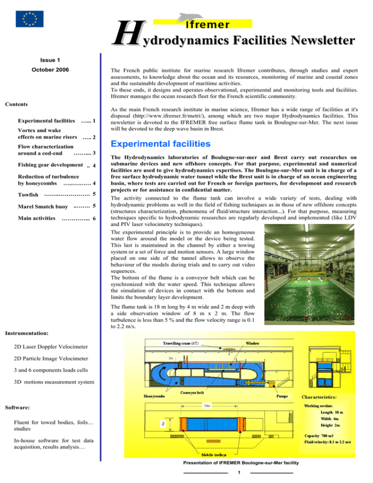
H ydrodynamics Facilities Newsletter Issue 1 October 2006 The French public institute for marine research Ifremer contributes, through studies and expert assessments, to knowledge about the ocean and its resources, monitoring of marine and coastal zones and the sustainable development of maritime activities. To these ends, it designs and operates observational, experimental and monitoring tools and facilities. Ifremer manages the ocean research fleet for the French scientific community. Contents Experimental facilities …... 1 Vortex and wake effects on marine risers ….. 2 Flow characterization …….... 3 around a cod-end Fishing gear development .. 4 Reduction of turbulence by honeycombs …..….…… 4 Towfish ……..……………. 5 Marel Smatch buoy ..……. 5 Main activities …………... 6 As the main French research institute in marine science, Ifremer has a wide range of facilities at it's disposal (http://www.ifremer.fr/metri/), among which are two major Hydrodynamics facilities. This newsletter is devoted to the IFREMER free surface flume tank in Boulogne-sur-Mer. The next issue will be devoted to the deep wave basin in Brest. Experimental facilities The Hydrodynamics laboratories of Boulogne-sur-mer and Brest carry out researches on submarine devices and new offshore concepts. For that purpose, experimental and numerical facilities are used to give hydrodynamics expertises. The Boulogne-sur-Mer unit is in charge of a free surface hydrodynamic water tunnel while the Brest unit is in charge of an ocean engineering basin, where tests are carried out for French or foreign partners, for development and research projects or for assistance in confidential matter. The activity connected to the flume tank can involve a wide variety of tests, dealing with hydrodynamic problems as well in the field of fishing techniques as in those of new offshore concepts (structures characterization, phenomena of fluid/structure interaction...). For that purpose, measuring techniques specific to hydrodynamic researches are regularly developed and implemented (like LDV and PIV laser velocimetry techniques). The experimental principle is to provide an homogeneous water flow around the model or the device being tested. This last is maintained in the channel by either a towing system or a set of force and motion sensors. A large window placed on one side of the tunnel allows to observe the behaviour of the models during trials and to carry out video sequences. The bottom of the flume is a conveyor belt which can be synchronized with the water speed. This technique allows the simulation of devices in contact with the bottom and limits the boundary layer development. The flume tank is 18 m long by 4 m wide and 2 m deep with a side observation window of 8 m x 2 m. The flow turbulence is less than 5 % and the flow velocity range is 0.1 to 2.2 m/s. Instrumentation: 2D Laser Doppler Velocimeter 2D Particle Image Velocimeter 3 and 6 components loads cells 3D motions measurement system Software: Fluent for towed bodies, foils… studies In-house software for test data acquisition, results analysis… Presentation of IFREMER Boulogne-sur-Mer facility 1 IFREMER Hydrodynamics Facilities Newsletter Vortex and wake effects on marine risers Area of interest Fishing technology Seismic devices Offshore engineering Renewable energy ROV - Submarine Other activities Vortex and wake effects on long risers are generally less well understood than other load effects acting on marine structures. As petroleum exploitation moves to deeper waters, avoiding interaction and collision between risers in an array becomes more and more difficult and expensive to obtain. Some ongoing research are performed for a better understanding of the hydrodynamic loads acting on a riser placed on the wake of an upstream one. The main concerns about riser interference are to be able to predict the VIV amplitude, shielding and wake effects and also to avoid the risk of collision between closely spaced risers. This research is conducted within a French JIP*. An experimentation involves the study of VIV for two closely spaced vertical pivoting risers in 2 m water depth**. Scaled model tests are performed to improve the understanding of the behaviour of dual riser interaction in uniform and steady current. A particular attention is paid on how fluid interaction between two cylinders of equal diameter in cross-flow can significantly modify their structural response in term of amplitude and frequency, compared to a single cylinder (see Figure 1). Figure 1: Rms amplitude response for risers in tandem Figure 2: PIV map on a circular cylinder (Vr from 4 to 15) Riser with strakes during trials The risers array is tested at Reynolds numbers from 5500 to 40000. The Figure 3: Response of two closely reduced mass and the natural frequency spaced risers (upstream cylinder on the right, the downstream one on the left) of the system are respectively 1.3 and 0.75 Hz. Experimental results presents VIV amplitude, shielding and wake effects, drag and lift amplification, together with detailed flow velocity measurements obtained from PIV (see Figure 2). Both inline and cross-flow responses are presented as functions of non dimensional numbers and demonstrate that wake effects can be relatively strong (see Figure 3) . Due to the complexity of the problem, experimental and numerical approaches are used simultaneously for a better understanding of the hydrodynamic loads acting on risers in tandem. * Acknowledgement to all JIP partners: Doris Eng., EGIM, IFP, Océanide, SAIPEM ** Vortex and Wake effects on closely spaced marine risers, G. Germain & al., FIV 2006, Vancouver 2 Issue 1 October 2006 http://www.ifremer.fr/boulogne/anglais/bassin.htm Flow characterization around a cod-end Area of interest The selectivity of fishing gears like trawls is conditioned by the net structure and flow characteristics. With the aim of a better understanding of interaction in presence of these flexible structures, we carried out an experimental study to determine and to analyse the flow over a cod-end*. Fishing technology Seismic devices Offshore engineering Renewable energy ROV - Submarine Other activities Improving the knowledge of the process involved in netting would improve their selectivity. Notably the small fish escapement could be facilitated by the mesh shape, the tensions in twines, the zones of high flow or dead water inside the fishing gear, the flow inside the meshes… If the flow around the whole structure is difficult to study, it is easier to focus in a first time on parts of the whole structure such as warps, doors or cod-end… The present work is devoted to the cod-end and has been done in the field of a European project (PREMECS II – contract QSR5-2002-01328). During the first phase of the project, tests were carried out in order to measure the shape and the tension in a cod-end. It was done for few netting characteristics, several catches and type of codend. The flow has not been measured Figure 1: Measurement near the netting with a 2D LDV system during this first phase due to the instabilities of the cod-end and especially of the catch inside the structure. So, it has been decided to realize a second phase of trials for the measurement of the flow inside and around a cod-end. To achieve this aim, a specific stiff cod-end has been carried out to avoid instabilities. This structure is perfectly stable in the flow and its geometrical shape is known. It has allowed to measure flow velocity profiles by Laser Doppler Velocimetry (LDV, see Figure 1) and Particle Image Velocimetry techniques. The pattern for all the velocity profiles (Figure 2) shown a well developed flow, for which the general characteristics are preserved inside the cod-end. The profile 6, just upstream the catch, shows very low water speeds inside the structure. At this point, the axial velocity component reaches 15% of the entry velocity while it reaches 50% on profile 5. In fact, near the catch the flow escapes the cod-end, while upstream the flow penetrates into the structure. The water outgoes near the catch with a pretty high velocity (the same order as the entry velocity). The measurements behind the catch confirmed the high turbulent flow in this zone (see Figure 3). Figure 2: LDV profiles of axial velocity inside and outside the cod-end. The vertical lines indicate the netting position (profile 2 at the entry, profile 7 at the beginning of the catch). Figure 3: Particle Image Velocimetry map around a cod-end * Flow characterization around a cod-end, G. Germain, J-V. Facq, D. Priour, Int. Maritime Congress, Lisbon, september 2005 3 IFREMER Hydrodynamics Facilities Newsletter Fishing gear development Area of interest Fishing technology Seismic devices Offshore engineering Renewable energy ROV - Submarine Other activities By-catch reduction devices are being used in some countries. Helps are needed to effectively introduce and transfer TED (Turtle Excluder Device) and BRD (By-catch Reduction Device) technology to those countries. To this end, technical developments continue on efforts to reduce by-catch and turtle capture in shrimp trawls in Guyana and Madagascar. The Turtle Excluder Device was created to lessen the impact of shrimp fishing on sea turtle populations. The TED is a metal grid of bars attached to a shrimp trawling net. It has an opening at either the top or the bottom, which creates a hatch allowing larger animals, such as sea turtles, to escape while keeping the shrimp inside. The BRD is used to reduce the capture of small fish by-catch. Introduction of both TED and BRD into shrimp fishery needs technical developments to obtain some well fitted devices. To this end, real scaled tests were conducted on flume tank to increase the efficiency of trawl nets including those devices. After tank trials, testing onboard a commercial shrimp trawler under normal operating conditions were carried out. Turtle Excluder and By-catch Reduction Devices trials Reduction of turbulence by honeycombs A numerical and experimental work* was carried out to evaluate the influence of honeycombs on the reduction of turbulence. In order to assess the evolution of the turbulence through these meshes, different characteristics of the honeycombs (length, diameter, thickness…) were tested. So, the influence of the structural parameters on the flow was highlighted. Numerical simulations were validated from comparisons on rate and scale of turbulence over the structure. The calculations used a CFD code and the experimental results were obtained using Laser Doppler Velocimetry and Particle Image Velocimetry. Numerical and experimental axial velocity comparison 150 mm downstream the honeycomb Comparison between PIV and CFD velocity map at the honeycomb exit * Reduction of turbulence by honeycombs, G. Germain, C. Candelier, S. Blarel, 10e Journées de l’Hydrodynamique, Nantes, France, mars 2005 4 Issue 1 October 2006 http://www.ifremer.fr/boulogne/anglais/bassin.htm Area of interest Fishing technology Seismic devices Offshore engineering Renewable energy ROV - Submarine Other activities INNOVA AS and HFT AS develop new deep towed depressor (ViperFish II) and towed undulating instrument carrier (Turbot). The ViperFish II is a combination of a hydrodynamic depressor design and a heavily ballasted clump weight, while Turbot has been designed as a terrain following/undulating towfish. Turbot in action Model tests have been carried out in the flume tank on the depressor alone and the Turbot towed behind the depressor. Results indicated that all the design criteria had been fulfilled, with an excellent behaviour and stability of the system. These towfish were piloted from the surface with an optimum control of the altitude and positioning. The Turbot also showed its aptitude to track the seabed “Marel Smatch TS” buoy The first specimen of the new buoy “Marel Smatch TS”, result of a collaboration between Ifremer and NKE, was presented in preview at Oceanology International meeting 2006. The first trials were programmed in order to determine the behaviour of this buoy in current. The selected mechanical concept was validated, and the operational limits in tidal currents were given. The buoy weighs less than 10 kg and its height is 1.20 m. It is easy to handle and install from a light boat. In its first version, the buoy analyses the temperature and salinity. The data collected are transferred autonomously by GSM towards a ground station. A more complete version for the measurement of other parameters like turbidity, fluorescence, dissolved oxygen and pH will also be developed. http://www.ifremer.fr/prod/marel/mareluk.htm Marel Smatch buoy in current 5 Boulogne-sur-Mer Hydrodynamic Water Tunnel Hydrodynamic tests are carried out on underwater vehicles and new offshore structures. Studies are mainly conducted at reduced scale in calm water or in current at a flow speed between 0,1 and 2 m/s. The free surface water tunnel is designed to test devices towed on the sea bottom (fishing-gears), submersed, propelled or anchored in deep water or floating on the surface. Underwater vehicle trials (Subeo) Study of a Remote Operated Vehicle (Comex Pro) Offshore structure (Saipem) Acknowledged experience ¾ Behavioural study and performance analysis ¾ Geometry and stress measurements ¾ Measurements of hydrodynamic coefficients ¾ Flow characterisation ¾ Shape optimiser and methods of validation ¾ Fluid structure interaction analysis Testing facilities Wing profil study (Thales) ¾ P.I.V. (Particle Image Velocimetry) ¾ Laser Doppler velocimeter (2 components) ¾ Laser tomography – Flow visualisation ¾ Load cells (3 and 6 components) Cod-end hydrodynamics Laser velocimeter measurement P.I.V. Flow map IFREMER Hydrodynamics Facilities France - E-mail : ggermain@ifremer.fr - http://www.ifremer.fr/boulogne/anglais/bassin.htm

