PG-256 - Varian Medical Systems
Anuncio
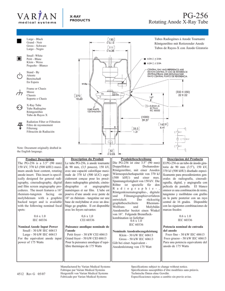
X-RAY PRODUCTS PG-256 Rotating Anode X-Ray Tube Tubes Radiogénes à Anode Tournante Röntgenröhre mit Rotierender Anode Tubos de Rayos-X con Ánodo Giratorio Large - Black Grand - Noir Gross - Schwarz Largo - Negro Small -White Petit - Blanc Klein - Weiss Pequeño - Blanco Stand - By Attente Bereitschaft En Espera Frame or Chasis Masse Chassis Soporte o Chasis X-Ray Tube Tube Radiogène Röntgenröhre Tubo de Rayos X Radiation Filter or Filtration Filtre de rayonnement Filterung Filtración de Radiación Note: Document originally drafted in the English language. Product Description The PG-256 is a 3.5” (90 mm) 150 kV, 370 kJ (500 kHU) maximum anode heat content, rotating anode insert. This insert is specifically designed for general radiography, cineradiography, digital and film screen angiography procedures. The insert features a 16° rhenium-tungsten facing on molybdenum with a graphite backed target and is available with the following nominal focal spots: Description du Produit Le tube PG-256, à anode tournante de 90 mm, (3,5 pouces), 150 kV, avec une capacité calorifique maximale de 370 kJ (500 kUC) espécialement conçue pour les procédures radiographie générale, cinéradiographie et angiographie numériques et sur film. L’tube est pourvu d’une anode avec pente de 16° en rhènium - tungsténe sur une base de molybdéne et avec un doublage ge graphite. Il est disponible avec les foyers suivantes: 0.6 x 1.0 IEC 60336 0,6 x 1,0 CEI 60336 Nominal Anode Input Power Small - 30 kW IEC 60613 Large - 50 kW IEC 60613 For the equivalent anode input power of 175 Watts Puissance anodique nominale de l’anode Petit foyer - 30 kW CEI 60613 Grand foyer - 50 kW CEI 60613 Pour la puissance anodique d’equilibre thermique de 175 Watts 4512 Rev G 05/07 Manufactured by Varian Medical Systems Fabrique par Varian Medical Systems Hergestellt von Varian Medical Systems Fabricado por Varian Medical Systems Produktbeschreibung Die PG-256 ist eine 3.5” (90 mm) Doppelfokus DrehanodenRöntgenröhre, mit einer Anoden Wärmespeicherkapazität von 370 kJ (500 kHU) und einer max. Spannungsfestigkeit von 150 kV. Die Röhre ist spezielle für den R a d i o g r a p h i e - , Röntgenkinematographie-, digitale und Filmangiographieverfahren entwickelt. Der rückseitig graphitbeschichtete RheniumWolframund Molybdän Anodenteller besitzt einen Winkel von 16°. Folgende Brennfleckkombination ist lieferbar: 0.6 x 1.0 IEC 60336 Nominale Anodenbezugsleistung Klein - 30 kW IEC 60613 Gross - 50 kW IEC 60613 Gilt bei einer Aquivalent Anodenleistung von 175 Watt Descripcion del Producto El PG-256 es un tubo de ánodo giratorio de 90 mm (3.5”), 150 kV, 370 kJ (500 kHU) diseñado especificamente para procedimientos generales de radiografía, cineradiografía, digital, y angiografía con pelicula de pantalla. El blanco emisor es una combinación de renio, tungsteno y molibdeno con grafito en la parte posterior con un rayo central de 16 grados. Disponible con las siguientes combinaciones de marcas focales: 0.6 x 1.0 IEC 60336 Potencia nominal de entrada del anodo Foco fine - 30 kW IEC 60613 Foco grueso - 50 kW IEC 60613 Para una potencia equivalente del anodo de 175 Watts Specifications subject to change without notice. Spécifications susceptibles d’être modifiées sans préavis. Technische Daten ohne Gewähr. Especificaciones sujetas a cambio sin previo aviso. PG-256 X-RAY PRODUCTS Abaques de Chargepour Pose Unique CEI 60613 3 Ø Constant Potential Nominal anode input power for the anode heat content 40%. IEC 60613 Single Load Ratings IEC 60613 Brennfleck - Belastungskurven IEC 60613 Diagramas de Exposición Radiográfica IEC 60613 50 Hz Puissance calorifique nominale de l’anode: 40%, CEI 60613 Thermische Anodenbezugsleistung bei einer Wärmespeicherung von 40%. IEC 60613 Copyright © 2007, Varian Medical Systems. All Rights Reserved. 2 Aproximadamente el poder de penetracion para obtener un almacenaje de calor del anodo de 40%. IEC 60613 PG-256 X-RAY PRODUCTS Abaques de Chargepour Pose Unique CEI 60613 3 Ø Constant Potential Nominal anode input power for the anode heat content 40%. IEC 60613 Single Load Ratings IEC 60613 Brennfleck - Belastungskurven IEC 60613 Diagramas de Exposición Radiográfica IEC 60613 60 Hz Puissance calorifique nominale de l’anode: 40%, CEI 60613 Thermische Anodenbezugsleistung bei einer Wärmespeicherung von 40%. IEC 60613 Copyright © 2007, Varian Medical Systems. All Rights Reserved. 3 Aproximadamente el poder de penetracion para obtener un almacenaje de calor del anodo de 40%. IEC 60613 PG-256 X-RAY PRODUCTS Abaques de Chargepour Pose Unique CEI 60613 3 Ø Constant Potential Nominal anode input power for the anode heat content 40%. IEC 60613 Single Load Ratings IEC 60613 Brennfleck - Belastungskurven IEC 60613 Diagramas de Exposición Radiográfica IEC 60613 150 Hz Puissance calorifique nominale de l’anode: 40%, CEI 60613 Thermische Anodenbezugsleistung bei einer Wärmespeicherung von 40%. IEC 60613 Copyright © 2007, Varian Medical Systems. All Rights Reserved. 4 Aproximadamente el poder de penetracion para obtener un almacenaje de calor del anodo de 40%. IEC 60613 PG-256 X-RAY PRODUCTS Abaques de Chargepour Pose Unique CEI 60613 3 Ø Constant Potential Nominal anode input power for the anode heat content 40%. IEC 60613 Single Load Ratings IEC 60613 Brennfleck - Belastungskurven IEC 60613 Diagramas de Exposición Radiográfica IEC 60613 180 Hz Puissance calorifique nominale de l’anode: 40%, CEI 60613 Thermische Anodenbezugsleistung bei einer Wärmespeicherung von 40%. IEC 60613 Copyright © 2007, Varian Medical Systems. All Rights Reserved. 5 Aproximadamente el poder de penetracion para obtener un almacenaje de calor del anodo de 40%. IEC 60613 PG-256 X-RAY PRODUCTS Cineradiographic Charts CINERADIOGRAPHIC RATINGS HOW TO USE CINERADIOGRAPHIC CHARTS General: With the Cineradiographic rating chart we can determine the maximum allowable kW of the Cine pulse, or with a given kW determine maximum time in seconds the cine run can progress. USING THE CINE RATING CHARTS: PG-256 3 Phase 1.0 Focal Spot Example: Determine maximum kW allowed with the following known factors: Maximum Pulse Width ........ 4 msec Exposures per Second ........60 Maximum Cine Run Time ... 10 seconds The Most common way of using the charts is to determine maximum time for any expected Cine run and maximum duty factor. With a known duty factor and Cine run time, kW can easily be determined. Calculate Duty Factor: (DF%) Definition of Terms Time in seconds: Total time of one Cine run, usually 5 to 12 seconds. DF% = Pulse Width (msec) x Frames per Second 10 Duty Factor in Percent (DF%): Actual time during one second the x-ray tube is producing x-rays. If we select a 4 msec pulse width and 50 exposures per second the x-ray tube will be producing x-rays for a total of 200 msec each second or 20% of the time. The higher the DF number, the more load placed on the x-ray tube. DF% = 4(msec) x 60 exp/sec = 240 10 10 = 24% Refer to Rating Chart PG-256 1.0 Focal Spot: 150/180 Hz 3 Phase At bottom of chart find 10 second line. Move vertically to intersection with 24% DF curve. Make a horizontal reference to left side of rating chart and note kW rating of 35.5 kW. Peak Pulse Power: Peak energy in watts of any one Cine Pulse. Can be any combination of kV and mA allowed by Radiography and Filament Emission curves. Example: 150/180 Hz kW = kV x mA. The kW of the exposure can be any combination of mA and kV allowed by the Radiographic and Filament Emission Charts. 80 kV at 400 mA equals The Cine rating charts are usable to 100% Anode Heat Storage. Exceeding 100% Anode Heat Content will cause anode track erosion with a high risk of tube destruction. 80,000 V x 0.4 A = 32,000 W or 32 kW Copyright © 2007, Varian Medical Systems. All Rights Reserved. 6 PG-256 X-RAY PRODUCTS Cineradiographic Charts IEC 60613 Abaques d’Cinéradiographie CEI 60613 Röntgenologische Belastungskurven IEC 60613 Diagramas de Exposición Cineradiográfica IEC 60613 3 Ø Constant Potential 150/180 Hz Nominal anode input power for the anode heat content 70%. IEC 60613 Puissance calorifique nominale de l’anode: 70%, CEI 60613 Thermische Anodenbezugsleistung bei einer Wärmespeicherung von 70%. IEC 60613 Copyright © 2007, Varian Medical Systems. All Rights Reserved. 7 Aproximadamente el poder de penetracion para obtener un almacenaje de calor del anodo de 70%. IEC 60613 PG-256 X-RAY PRODUCTS Angiographic Ratings ANGIOGRAPHIC RATINGS HOW TO USE ANGIOGRAPHIC CHARTS General: Serial Radiography puts a severe demand on the x-ray tube due to the large number of exposures made in rapid succession. Intervals between exposures are fixed and so short that it is not possible for the anode track to cool to any extent during the exposure series. Therefore, the temperature of the anode track increases from exposure to exposure. The kW values used in the angiographic charts have been determined to prevent damage to the anode. The angiographic rating charts are usable to Maximum anode heat content. Exceeding Maximum Heat Content will cause anode track erosion with a high risk of tube destruction. USING THE CHARTS: Determine the number of exposures in Series: With cut film angiography the number of exposures are known, however in Digital Angiography the number of exposures commonly are not known. When determining the number of exposures, assume worst case or past history. Note: Most angiographic x-ray tubes fail from underestimating the number of exposures made in a series. Determine kW of each exposure in Series: Referring to chart ⎯find block under “Number of Exposures in Series” that is greater than or equal to expected number of exposures in Series. On left side directly opposite this block under “Exposure Rate per Second” column, select maximum rate per second that will be used for the exposure series. At the intersection of exposure rate and exposure time in seconds, find maximum kW allowed for each exposure. Definition of Terms Number of Exposures in Series: The number of exposures made in succession or the number of exposures made during one contrast injection. Exposure Rate: The number of exposures made per second. For a series of exposures where the exposure rate changes, it must be assumed that all exposures will be made at the maximum rate. For example, if during a series 10 exposures will occur at one per second and 30 exposures at 4 per second, use the kW ratings in the 40 exposure column at 4 per second rate. kW = pkV x mA: The kW of the exposure can be any combination of mA and pkV allowed by the Radiographic and Filament Emission charts. For Example: 80 pkV and 500 mA = 40 kW Example: From chart PG-256 150/180 Hz 3 Phase 1.0 Focal Spot, determine kW allowed with following known factors. Maximum number of exposures ..............40 Exposure time .050 second (50 milliseconds) Maximum Exposure per second ..............4 Exposure Time: Time in seconds of each exposure. From chart find 40 exposure block. On left side directly opposite this block under “Exposure Rate per Second” column, select 4 exposures per second. Find .050 seconds at top of chart. At intersection of exposure rate line and exposure time, find 35.6 kW. Copyright © 2007, Varian Medical Systems. All Rights Reserved. 8 PG-256 X-RAY PRODUCTS Angiographic Ratings IEC 60613 Caractéristiques Pour L’Angiographie CEI 60613 Angiographische Nennleistungen IEC 60613 Gradaciones Angiografica IEC 60613 0.6 Focal Spot 3Ø 16 Degrees 150/180 Hz 0,6 Dimension Focale 3Ø 16 Degrés 150/180 Hz 0.6 Brennpunkt 3Ø 16 Grad 150/180 Hz 0.6 De Marcas Focales 3Ø 16 Grados 150/180 Hz Note: 1. (kW) of Exposure Equals mA x kV. For Example: 70 kV x 300 mA = 21 kW. 2. Exposures less than .010 seconds will have a kW rating same as .010 seconds. Remarque: 1. (kW) en exposition égale kV x mA. Par exemple: 70 kV x 300 mA = 21 kW. 2. Les expositions inférieures à 0.010 sec. ent les mémes valuers en kW que celles de 0.010 sec. Anmerkungen: 1. (kW) der Belichtung is gleich mA x kV Zum Beispiel: 70 kV x 300 mA = 21 kW. 2. Belichtungen von weniger als .010 Sekunden haben die gleichen kW Werte wie die von .010 Sekunden. Nota: 1. (kW) De exposición se calcula multiplicando mA x kV-porejemplo: 70 kV x 300 mA = 21 kW. 2. Para Exposicione de Menos de .010 segundos, el resultado en (kW) seria lomismo que el de .010 segundos. Nominal anode input power for the anode heat content 70%. IEC 60613 Puissance calorifique nominale de l’anode: 70%, CEI 60613 Thermische Anodenbezugsleistung bei einer Wärmespeicherung von 70%. IEC 60613 Aproximadamente el poder de penetracion para obtener un almacenaje de calor del anodo de 70%. IEC 60613 Copyright © 2007, Varian Medical Systems. All Rights Reserved. 9 PG-256 X-RAY PRODUCTS Angiographic Ratings IEC 60613 1.0 Focal Spot 3Ø 16 Degrees 150/180 Hz 1,0 Dimension Focale 3Ø 16 Degrés 150/180 Hz 1.0 Brennpunkt 3Ø 16 Grad 150/180 Hz 1.0 De Marcas Focales 3Ø 16 Grados 150/180 Hz Caractéristiques Pour L’Angiographie CEI 60613 Angiographische Nennleistungen IEC 60613 Gradaciones Angiografica IEC 60613 Note: 1. (kW) of Exposure Equals mA x kV. For Example: 70 kV x 300 mA = 21 kW. 2. Exposures less than .010 seconds will have a kW rating same as .010 seconds. Remarque: 1. (kW) en exposition égale kV x mA. Par exemple: 70 kV x 300 mA = 21 kW. 2. Les expositions inférieures à 0.010 sec. ent les mémes valuers en kW que celles de 0.010 sec. Anmerkungen: 1. (kW) der Belichtung is gleich mA x kV Zum Beispiel: 70 kV x 300 mA = 21 kW. 2. Belichtungen von weniger als .010 Sekunden haben die gleichen kW Werte wie die von .010 Sekunden. Nota: 1. (kW) De exposición se calcula multiplicando mA x kV-porejemplo: 70 kV x 300 mA = 21 kW. 2. Para Exposicione de Menos de .010 segundos, el resultado en (kW) seria lomismo que el de .010 segundos. Nominal anode input power for the anode heat content 70%. IEC 60613 Puissance calorifique nominale de l’anode: 70%, CEI 60613 Thermische Anodenbezugsleistung bei einer Wärmespeicherung von 70%. IEC 60613 Aproximadamente el poder de penetracion para obtener un almacenaje de calor del anodo de 70%. IEC 60613 Copyright © 2007, Varian Medical Systems. All Rights Reserved. 10 PG-256 X-RAY PRODUCTS Filament Emission Charts IEC 60613 Abaques d’ Émissions des Filaments CEI 60613 Heizfadenemissionsdiagramm IEC 60613 Curvas de Emisión de los Filamentos IEC 60613 3 Ø FULL WAVE THREE PHASE EMISSION (± .15 A) PG-256 0.6 THREE PHASE EMISSION (± .15 A) PG-256 1.0 Note: When using these emission curves for trial exposures, refer to the power rating curves shown for maximum kV, tube emission, filament current, exposure time, and target speed. Remarque: Lors de l’utilisation de ces abaques pour des expositions d’essai, référez-vous aux courbes maximales de kV, d’émission du filament, de temps d’exposition et de vitesse de rotation. Anmerkung: Wenn Sie diese Emissionskurven für Testaufnahmen verwenden, beziehen Sie sich hierbei auf die entsprechenden Nennleistungskurven für max. kV-Werte, Röhrenemission, Heizstrom, und Anodendrehzahl. Nota: Si utiliza estas curvas de emisión para exposiciones de prueba, refiérase a las curvas de gradación de potencia para el máximo de kV, tubo de emisión, corriente en los filamentos, tiempo de exposión, y a las curvas de velocidad del objetivo. Copyright © 2007, Varian Medical Systems. All Rights Reserved. 11 PG-256 X-RAY PRODUCTS Anode Heating & Cooling Chart Abaques d’ Échauffement et de Refroidissement de L’Anode Anoden Aufheiz - und Abkühlkurven Curvas de Calentamiento y Enfriamiento del Anodo Time (Minutes) Durée (Minutes) Zeit (Minuten) Tiempo (Minutos) X-RAY PRODUCTS Salt Lake City, UT Charleston, SC 1-801-972-5000 1-843-767-3005 www.varian.com Copyright © 2007, Varian Medical Systems. All Rights Reserved. 12
