24si™ hd replacement parts instructions
Anuncio
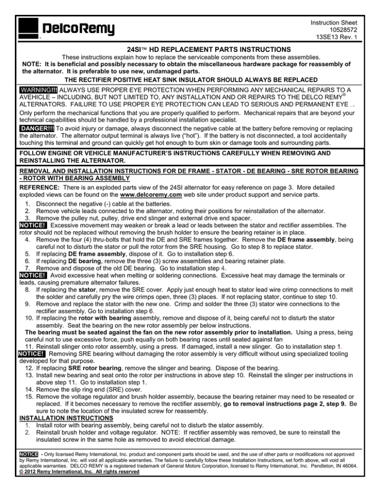
. Instruction Sheet 10528572 13SE13 Rev. 1 24SI™ HD REPLACEMENT PARTS INSTRUCTIONS These instructions explain how to replace the serviceable components from these assemblies. NOTE: It is beneficial and possibly necessary to obtain the miscellaneous hardware package for reassembly of the alternator. It is preferable to use new, undamaged parts. THE RECTIFIER POSITIVE HEAT SINK INSULATOR SHOULD ALWAYS BE REPLACED WARNING!!!!ALWAYS USE PROPER EYE PROTECTION WHEN PERFORMING ANY MECHANICAL REPAIRS TO A ® AVEHICLE – INCLUDING, BUT NOT LIMITED TO, ANY INSTALLATION AND OR REPAIRS TO THE DELCO REMY ALTERNATORS. FAILURE TO USE PROPER EYE PROTECTION CAN LEAD TO SERIOUS AND PERMANENT EYE . Only perform the mechanical functions that you are properly qualified to perform. Mechanical repairs that are beyond your technical capabilities should be handled by a professional installation specialist. DANGER!!! To avoid injury or damage, always disconnect the negative cable at the battery before removing or replacing the alternator. The alternator output terminal is always live (“hot”). If the battery is not disconnected, a tool accidentally touching this terminal and ground can quickly get hot enough to burn skin or damage tools and surrounding parts. DAM AGE FOLLOW ENGINE OR VEHICLE MANUFACTURER’S INSTRUCTIONS CAREFULLY WHEN REMOVING AND REINSTALLING THE ALTERNATOR. REMOVAL AND INSTALLATION INSTRUCTIONS FOR DE FRAME - STATOR - DE BEARING - SRE ROTOR BEARING - ROTOR WITH BEARING ASSEMBLY REFERENCE: There is an exploded parts view of the 24SI alternator for easy reference on page 3. More detailed exploded views can be found on the www.delcoremy.com web site under product support and service parts. 1. Disconnect the negative (-) cable at the batteries. 2. Remove vehicle leads connected to the alternator, noting their positions for reinstallation of the alternator. 3. Remove the pulley nut, pulley, drive end slinger and external drive end spacer. NOTICE!! Excessive movement may weaken or break a lead or leads between the stator and rectifier assemblies. The rotor should not be replaced without removing the brush holder to ensure the bearing retainer is in place. 4. Remove the four (4) thru-bolts that hold the DE and SRE frames together. Remove the DE frame assembly, being careful not to disturb the stator or pull the rotor from the SRE housing. Go to step 8 to replace stator. 5. If replacing DE frame assembly, dispose of it. Go to installation step 6. 6. If replacing DE bearing, remove the three (3) screw assemblies and bearing retainer plate. 7. Remove and dispose of the old DE bearing. Go to installation step 4. NOTICE!! Avoid excessive heat when melting or soldering connections. Excessive heat may damage the terminals or leads, causing premature alternator failures. 8. If replacing the stator, remove the SRE cover. Apply just enough heat to stator lead wire crimp connections to melt the solder and carefully pry the wire crimps open, three (3) places. If not replacing stator, continue to step 10. 9. Remove and replace the stator with the new one. Crimp and solder the three (3) stator wire connections to the rectifier assembly. Go to installation step 6. 10. If replacing the rotor with bearing assembly, remove and dispose of it, being careful not to disturb the stator assembly. Seat the bearing on the new rotor assembly per below instructions. The bearing must be seated against the fan on the new rotor assembly prior to installation. Using a press, being careful not to use excessive force, push equally on both bearing races until seated against fan 11. Reinstall slinger onto rotor assembly, using a press. If damaged, install a new slinger. Go to installation step 1. NOTICE!! Removing SRE bearing without damaging the rotor assembly is very difficult without using specialized tooling developed for that purpose. 12. If replacing SRE rotor bearing, remove the slinger and bearing. Dispose of the bearing. 13. Install new bearing and seat onto the rotor per instructions in above step 10. Reinstall the slinger per instructions in above step 11. Go to installation step 1. 14. Remove the slip ring end (SRE) cover. 15. Remove the voltage regulator and brush holder assembly, because the bearing retainer may need to be reseated or replaced. If it becomes necessary to remove the rectifier assembly, go to removal instructions page 2, step 9. Be sure to note the location of the insulated screw for reassembly. INSTALLATION INSTRUCTIONS 1. Install rotor with bearing assembly, being careful not to disturb the stator assembly. 2. Reinstall brush holder and voltage regulator. NOTE: If rectifier assembly was removed, be sure to reinstall the insulated screw in the same hole as removed to avoid electrical damage. NOTICE - Only licensed Remy International, Inc. product and component parts should be used, and the use of other parts or modifications not approved by Remy International, Inc. will void all applicable warranties. The failure to carefully follow these Installation Instructions, set forth above, will void all applicable warranties. DELCO REMY is a registered trademark of General Motors Corporation, licensed to Remy International, Inc. Pendleton, IN 46064. © 2012 Remy International, Inc. All rights reserved 3. Crimp and solder the voltage regulator connection and rectifier connections if necessary. 4. Install new drive end bearing assembly into drive end frame. Push bearing into frame bore until it is seated, by applying force against the outer race only, using a press. Do not use excessive force. 5. Reinstall or replace bearing retainer plate. Torque the three (3) screws & lock washer assemblies to 5.0-9.0 Nm (44-80 lb in). 6. Reinstall the drive end frame assembly, being careful to line up the non-threaded mounting lugs. 7. Reinstall the four (4) thru-bolts. Using a crossing pattern, torque the four (4) thru-bolts to 7.8-9.2 Nm (90-120 lb in). 8. Reinstall slip ring end cover and torque the mounting screw assemblies to 2.2-2.8 Nm (19-25 lb in). 9. Reinstall external DE end spacer, DE slinger, pulley and pulley nut. Tighten pulley nut to 95-108 Nm (70-80 lb ft). 10. Reinstall alternator according to engine or vehicle manufacturer’s instructions. 11. Reattach the battery (+) terminal lead, as removed, and torque nut to 9.0-13.0 Nm (80-120 lb in). 12. Reconnect the negative (-) cable at the battery. REMOVAL AND INSTALLATION INSTRUCTION FOR SRE COVER - VOLTAGE REGULATOR - BRUSH ASSEMBLY RECTIFIER ASSEMBLY- SRE FRAME REFERENCE: There is an exploded parts view of the 24SI alternator for easy reference on page 3. More detailed exploded views can be found on the www.delcoremy.com web site under products and service parts. 1. Disconnect the negative (-) cable at the batteries. 2. Remove vehicle leads connected to the alternator, noting their positions for reinstallation of the alternator. 3. Remove the SRE cover. If replacing, dispose of it and go to installation step 9. NOTICE! Avoid excessive heat when melting or soldering connections. Excessive heat may damage the terminals or leads, causing premature alternator failures. 4. If replacing the regulator, separate regulator from the rectifier assembly by applying just enough heat to the connection to melt solder and carefully pry the crimp open 5. Remove the regulator mounting screws and bushings, carefully noting parts orientation for reassembly. Dispose of regulator and go to installation step 7. 6. If replacing brush assembly, remove the four (4) thru-bolts holding the DE and SRE frames together and remove the regulator as noted in steps 4 & 5 above. 7. Remove and dispose of the brush assembly and go to installation step 4. NOTE: If it should require removing the rectifier continue to step 8. 8. If replacing rectifier assembly, separate rectifier assembly from stator by applying just enough heat to melt solder at the three (3) wire crimp stator connections and carefully prying wire crimps open. If not replacing rectifier assembly, remove as a unit with the regulator attached. 9. Remove rectifier assembly fasteners. WARNING! Note location of the insulated screw assembly on the end of the positive heat sink next to the battery terminal for reassembly. Failure to use an insulated screw assembly here will cause a ground and damage the alternator and potentially surrounding parts. 10. Remove heat sink insulator, being extremely careful not to damage surface of SRE casting. 11. Dispose of the old rectifier assembly. Go to installation step 5. 12. Remove and dispose of SRE frame by removing the four (4) thru-bolts that hold DE & SRE frames together. Go to installation step 1. INSTALLATION INSTRUCTIONS 1. Place new SRE frame over the stator leads, being careful to line up the non-threaded mounting lugs. 2. Using a crossing pattern, install and torque the four (4) thru-bolts to 7.8-9.2 Nm (90-120 lb in), 3. Reinstall and seat the bearing retainer in SRE frame bore. If damaged, install a new retainer. 4. Reinstall brush holder assembly. Prior to assembly, push the brushes back, and insert a 17 mm (.7”) pin to hold them back to allow clearance for the slip ring to enter. 5. Place new heat sink insulator onto positive heat sink of the new rectifier assembly, if necessary. Cover negative diodes with a heat sink compound compatible with semiconductor materials. Use a compound that can with stand a temperature range of -40C to 180C (- 104F to 356F). 6. Reinstall five (5) mounting screws into the rectifier assembly, ensuring the one (1) insulated screw is installed in the hole on the rounded end of the positive heat sink, as removed. Torque all screws to 2.2-2.8 N-m (1925 lb in). 7. Install voltage regulator by replacing two (2) bushings and three (3) mounting screws into the voltage regulator, ensuring the one insulated screw is used in terminal that connects to the brush holder. Torque all screws to 2.2-2.8 N-m (19-25 lb in). 8. Crimp and solder rectifier assembly terminals to three (3) stator wires and to voltage regulator strap. 9. Install SRE cover and torque the mounting screw assemblies to 2.2-2.8 N-m (19-25 lb in). 10. Reinstall alternator according to engine or vehicle manufacturer’s instructions. 11. Reattach the battery (+) terminal lead to alternator battery terminal and torque nut to 9.0-13.0 N-m (80-120 lb in). 12. Reconnect the negative (-) cable at the battery. NOTICE - Only licensed Remy International, Inc. product and component parts should be used, and the use of other parts or modifications not approved by Remy International, Inc. will void all applicable warranties. The failure to carefully follow these Installation Instructions, set forth above, will void all applicable warranties. DELCO REMY is a registered trademark of General Motors Corporation, licensed to Remy International, Inc. Pendleton, IN 46064. © 2012 Remy International, Inc. All rights reserved 2 10528572 24SI™ SERVICE PARTS EXPLODED PARTS VIEWS OF 24SI™ ALTERNATORS AND OTHER PRODUCTS ARE AVAILABLE ON THE www.delcoremy,com WEB SITE UNDER PRODUCTS AND SERVICE PARTS NOTE: It is beneficial and possibly necessary to obtain this hardware package for reassembly of the alternator. It is preferable to use new, undamaged parts. THE RECTIFIER POSITIVE HEAT SINK INSULATOR SHOULD ALWAYS BE REPLACED 24SI SERVICE PARTS PACKAGES 11. 12. 13. 14. 15. 16. 17. 18. 19. 20. DRIVE END FRAME WITH BEARING STATOR ASSEMBLY ROTOR WITH PRESSED ON BEARING SLIP RING END (SRE) FRAME BRUSH HOLDER WITH BRUSHES ASSEMBLY DIODE RECTIFIER ASSEMBLY VOLTAGE REGULATOR DRIVE END (DE) BEARING SLIP RING END ROTOR BEARING HARDWARE PACKAGE HARDWARE PACKAGE P/N 10520982 MAY BE NECESSARY Technical support: USA 800 854 0076, Mexico 01 800 000 7378, Brazil 0800 703 3526, South America 55 11 2106 6510 or visit delcoremy.com NOTICE - Only licensed Remy International, Inc. product and component parts should be used, and the use of other parts or modifications not approved by Remy International, Inc. will void all applicable warranties. The failure to carefully follow these Installation Instructions, set forth above, will void all applicable warranties. DELCO REMY is a registered trademark of General Motors Corporation, licensed to Remy International, Inc. Pendleton, IN 46064. © 2012 Remy International, Inc. All rights reserved 3 10528572 Hoja de Instrucciones 10528572 13SE13 Rev. 1 . INSTRUCCIONES DE REEMPLAZO PARA PARTES DE 24SI™ HD Rev. 3 Estas instrucciones explican como reemplazar los componentes de servicio para estos ensambles NOTA: Es beneficioso y posiblemente necesario obtener el kit de reparación N/P 10520892 para re-ensamble del alternador. Es preferible utilizar piezas nuevas y sin daño. EL DISIPADOR POSITIVO DEL RECTIFICADOR DEBE SER REEMPLAZADO SIEMPRE ¡¡¡PRECAUCIÓN!!!!USE SIEMPRE PROTECCIÓN OCULAR CUANDO REALIZAR CUALQUIER ACTIVIDAD RELACIONADA CON LA REPARACIÓN MECÁNICA A UN VEHÍCULO, INCLUYENDO MÁS NO LIMITANDO A CUALQUIER REPARACIÓN O INSTALACIÓN DE MOTORES DE ARRANQUE DELCO REMY. OMITIR EL USO DE PROTECCIÓN OCULAR APROPIADA PUEDE RESULTAR EN DAÑOS Y LESIONES PERMANENTES A LOS OJOS. Ejecute solamente las funciones mecánicas que está apropiadamente calificado para realizar. Las reparaciones mecánicas que se encuentran fuera de sus capacidades técnicas deben ser manejadas por especialistas profesionales de instalación. PELIGRO!!! Para evitar lesiones o daño, siempre desconecte el cable negativo (-) de batería antes de remover o reemplazar los cables del alternador, la terminal de salida del alternador siempre esta viva (“caliente”). Si la batería no es desconectada y una herramienta toca accidentalmente esta terminal y tierra; puede rápidamente calentarse y provocar quemaduras de piel o dañar la herramienta y partes a su alrededor. ¡ALERTA! SIGA LAS INSTRUCCIONES DEL FABRICANTE DE LA MÁQUINA (MOTOR DE COMBUSTIÓN INTERNA) Y/O DEL VEHÍCULO AL MOMENTO DE INSTALAR Y REMOVER EL MOTOR DE ARRANQUE INSTRUCCIONES PARA REMOVER E INSTALAR TAPA FRONTAL - ESTATOR – BALERO FRONTAL- BALERO DE ROTOR - ROTOR CON ENSAMBLE BALERO REFERENCIA: Para una referencia fácil, existe una vista explosionada del alternador 24SI en la pagina 3, vistas explosionadas con más detalle se pueden encontrar en “Product Support and Service Parts” en la pagina www.delcoremy.com 1. Desconecte el cable negativo (-) en la batería 2. Remueva los cables del vehiculo conectados al alternador, identifique sus posiciones para reinstalar el alternador. 3. Remueva la tuerca de la polea, el espaciador externo y el espaciador interno. ¡NOTA!! Movimiento excesivo puede debilitar o romper una o varias terminales entre el estator y el rectificador, el rotor no debe ser remplazado sin remover el ensamble porta carbones para asegurar que el retenedor del balero se encuentra en su lugar. 4. Remueva los cuatro (4) tornillos pasantes que mantienen tapa frontal y trasera juntas. Remueva el ensamble de tapa frontal, sea cuidadoso de no dañar el estator o retirar el rotor de la tapa trasera. Vaya al paso 8 para remplazar el estator. 5. Si esta reemplazando el ensamble de tapa frontal, deséchela y vaya al paso # 6 del proceso de instalación. 6. Si esta reemplazando el balero frontal, remueva los tres (3) tornillos y el plato retenedor. 7. Remueva y deseche el balero frontal viejo y vaya al paso 4 del proceso de instalación. ¡NOTA!! Evite calor excesivo cuando derrita o suelde las conexiones. El calor excesivo puede dañar las terminales o cables, causando fallas de alternador prematuras. 8. Si esta reemplazando el estator, remueva la cubierta trasera. Aplique solo el calor suficiente a las conexiones crimpadas del estator para derretir la soldadura y separe cuidadosamente las conexiones crimpadas, tres (3) lugares. Si no esta remplazando el estator continúe en el punto 10 9. Remueva y reemplace el estator por uno nuevo. Crimpe y suelde las tres (3) conexiones del estator al puente rectificador. Vaya al paso 6 del proceso de instalación.. 10. Si esta remplazando el ensamble rotor con balero, remueva y deseche el ensamble Viejo, sea cuidadoso de no dañar el ensamble estator, asiente el balero en el Nuevo rotor de acuerdo a las instrucciones siguientes. El balero debe estar asentado contra el ventilador en el Nuevo ensamble rotor antes de que este sea instalado. Usando una prensa y siendo cuidadoso de no usar fuerza excesiva, empuje uniformemente en las dos caras del balero hasta que se asiente contra el balero 11. Usando una prensa re-instale el espaciador interno en el ensamble rotor, si este esta dañado, use un espaciador nuevo. Vaya al paso 1 del proceso de instalación. ¡NOTA!! Remover el balero trasero sin dañar el ensamble rotor es muy difícil si no se usan herramientas especiales desarrolladas para ese propósito. NOTA - Solamente deben ser usados productos y componentes Remy International Inc., el uso de otras partes o modificaciones no aprobadas por Remy International Inc. anulará todas las garantías aplicables. No seguir cuidadosamente las instrucciones de instalaciones expuestas en este documento anulará todas las garantías aplicables. Delco RemyⓇ es una marca registrada de General Motors Corporation, autorizada bajo licencia a Remy International Inc., Pendleton, IN 46064. © 2012 Remy International Inc. Todos los derechos 4 10528572 12. Si esta remplazando el balero trasero, remueva el espaciador y el balero, deseche el balero viejo. 13. Instale el balero nuevo y asiéntelo en rotor de acuerdo a las instrucciones del paso 10 arriba. Reinstale el espaciador de acuerdo a las instrucciones del paso 11 arriba. Vaya al paso 1 del proceso de instalación. 14. Remueva la cubierta del lado del anillo rozante. 15. Remueva el regulador de voltaje y el ensamble porta carbones, debido a pudiera ser necesario re-asentar o reemplazar el balero. Si es necesario remover el ensamble rectificador, vaya a instrucciones de remover en la pagina 2 paso 9. asegúrese de identificar la posición del tornillo aislado para su re-ensamble. INSTRUCCIONES DE INSTALACION 1. Instale el rotor con ensamble de balero, sea cuidadoso de no dañar el ensamble estator. 2. Re-instale el porta carbones y el regulador de voltaje. NOTA: si el puente rectificador fue removido; asegúrese de instalar el tornillo aislado en la misma posición para evitar daño eléctrico. 3. Crimpe y suelde la conexión del regulador de voltaje y la del puente rectificador si es necesario. 4. Instale un ensamble nuevo de balero en la tapa frontal usando una prensa; empuje el balero en la tapa hasta que quede bien asentado, aplicando fuerza solo a la pista externa, No use fuerza excesiva. 5. Reinstale o reemplace el plato retenedor. apriete los tres (3) ens. tornillo y roldana a 5.0-9.0 Nm (44-80 lb in). 6. Reinstale el ensamble tapa frontal, siendo cuidadoso de alinear las terminales de montaje sin rosca. 7. Reinstale los cuatro (4) tornillos de montaje, usando un patrón cruzado, apriete tornillos a 7.8-9.2 Nm (90-120 lb in). 8. Reinstale la cubierta del colector y torque los tornillos de montaje a 2.2-2.8 Nm (19-25 lb in). 9. Reinstale el espaciador externo frontal, el espaciador interno, la polea y tuerca de polea, apriete la tuerca de polea a 95-108 Nm (70-80 lb ft). 10. Reinstale el alternador de acuerdo a las instrucciones del fabricante del vehiculo. 11. Reconecte el cable de batería (+) como fue removida, apriete la tuerca a 9.0-13.0 Nm (80-120 lb in). 12. Reconecte el cable negativo (-) en la batería. INSTRUCCIONES PARA REMOVER E INSTALAR LA CUBIERTA TAPA TRASERA – REGULADOR DE VOLTAJE – ENSAMBLE PORTACARBONES – ENSAMBLE RECTIFICADOR – TAPA TRASERA REFERENCIA: Para una referencia fácil, existe una vista explosionada del alternador 24SI en la pagina 3, vistas explosionadas con mas detalle se pueden encontrar en “Product Support and Service Parts” en la pagina www.delcoremy.com 1. Desconecte el cable negativo (-) en la batería 2. Remueva los cables del vehiculo conectados al alternador, identifique sus posiciones para reinstalar el alternador. 3. Remueva la cubierta trasera. Si se esta reemplazando, deséchela y vaya al paso de instalación 9. ¡NOTA!! Evite calor excesivo cuando derrita o suelde las conexiones. Calor excesivo puede dañar las terminales o cables, causando fallas de alternador prematuras. 4. Si se reemplaza el regulador, separe el regulador del ensamble puente rectificador aplicando solo el calor necesario a la conexión para derretir la soldadura y cuidadosamente abra el crimpado para liberar las partes. 5. Remueva los tornillos de montaje del regulador y los bujes, cuidadosamente identifique la orientación de las partes para su reensamble. Deseche el regulador y vaya al paso de instalación 7. 6. Si se reemplaza el ensamble porta carbones, remueva los cuatro (4) tornillos de montaje sujetando las tapas trasera y delantera juntas y remueva el regulador según pasos 4 y 5 arriba. 7. Remueva y deseche el ensamble porta carbones y vaya al paso de instalación 4. NOTA: si es necesario remover el puente rectificador continúe al paso 8. 8. Si reemplaza el puente rectificador, separe el puente rectificador del estator aplicando solo el calor necesario para derretir la soldadura en las tres (3) conexiones crimpadas del estator y cuidadosamente abra el crimpado para liberar las partes. Si no se remplaza el puente rectificador remueva todo junto con el regulador unido. 9. Remueva los tornillos de ensamble del puente rectificador. ALERTA! Tome nota de la posición del tornillo aislado al final del disipador de calor positive junto a la terminal de batería para su posterior reensamble. Falla al no usar el tornillo aislado causara un aterrizado y daño al alternador y potencialmente a partes en su alrededor. 10. Remueva el aislador del disipador de calor, sea extremadamente cuidadoso de no dañar la superficie de la tapa trasera. 11. Deseche el puente rectificador viejo. Vaya al paso de instalación 5. 12. Remueva y deseche la tapa trasera removiendo los cuatro (4) tornillos pasados que sujetan las dos tapas juntas. Vaya al paso de instalación 1. INSTRUCCIONES DE INSTALACION 1. Coloque la tapa trasera nueva sobre las terminales del estator, siendo cuidadoso de alinear las terminales sin cuerda. 2. Usando un patrón cruzado, instale y apriete los cuatro (4) tornillos pasantes a 7.8-9.2 Nm (90-120 lb in), NOTA - Solamente deben ser usados productos y componentes Remy International Inc., el uso de otras partes o modificaciones no aprobadas por Remy International Inc. anulará todas las garantías aplicables. No seguir cuidadosamente las instrucciones de instalaciones expuestas en este documento anulará todas las garantías aplicables. Delco RemyⓇ es una marca registrada de General Motors Corporation, autorizada bajo licencia a Remy International Inc., Pendleton, IN 46064. © 2012 Remy International Inc. Todos los derechos 5 10528572 3. Reinstale y asiente el retenedor del balero en la tapa trasera, si esta dañado instale un nuevo retenedor. 4. Reinstale el ensamble porta carbones, antes de instalarlo empuje los carbones hacia atrás e inserte un pin de 17 mm (.7”) para sujetarlos y así tener espacio para que entre el colector del rotor. 5. Coloque el aislador del disipador en el disipador positivo del nuevo ensamble puente rectificador, si necesario, cubra los diodos negativos con pasta Silicon compatible con materiales semiconductores y que soporte temperaturas de -40C a 180C (- 104F a 356F). 6. Reinstale los cinco (5) tornillos de montaje del puente rectificador, asegurándose que el único (1) tornillo aislado es instalado en el agujero redondeado al final del disipador de calor, de donde fue removido. apriete todos los tornillos a 2.2-2.8 N-m (19-25 lb in). 7. Instale el regulador de voltaje remplazando dos (2) bujes y tres (3) tornillos de montaje en el regulador de voltaje, asegurándose que el único (1) tornillo aislado es usado en la terminal que conecta al porta carbones. apriete todos los tornillos a 2.2-2.8 N-m (19-25 lb in). 8. Crimpe y suelde las terminales del puente rectificador a las tres (3) terminales del estator y al conector del regulador de voltaje. 9. Instale la cubierta trasera y apriete los tornillos de montaje a 2.2-2.8 N-m (19-25 lb in). 10. Reinstale el alternador de acuerdo a las instrucciones del fabricante del vehiculo. 11. Reconecte el cable de batería (+) como fue removida, apriete la tuerca a 9.0-13.0 Nm (80-120 lb in). 12. Reconecte el cable negativo (-) en la batería. PARTES DE SERVICIO 24SI™ VISTAS DE LAS PARTES EXPLOSIONADAS DEL ALTERNADOR 24SI™ Y OTROS PRODUCTOS ESTAN DISPONIBLES EN LA PAGINA WEB www.delcoremy,com , BAJO EL MENU “PRODUCTS AND SERVICE PARTS” NOTA - Solamente deben ser usados productos y componentes Remy International Inc., el uso de otras partes o modificaciones no aprobadas por Remy International Inc. anulará todas las garantías aplicables. No seguir cuidadosamente las instrucciones de instalaciones expuestas en este documento anulará todas las garantías aplicables. Delco RemyⓇ es una marca registrada de General Motors Corporation, autorizada bajo licencia a Remy International Inc., Pendleton, IN 46064. © 2012 Remy International Inc. Todos los derechos 6 NOTA: Es benéfico y posiblemente necesario obtener estos kits de servicio para re-ensamble del alternador, es preferible usar partes nuevas y no dañadas. EL AISLADOR DEL DISIPADOR DE CALOR DEL PUENTE RECTIFICADOR SIEMPRE SE DEBE REMPLAZAR 1. 2. 3. 4. 5. 6. 7. 8. 9. 10. KITS DE PARTES DE SERVICIO 24SI TAPA DELANTERA (DE) CON BALERO ENSAMBLE ESTATOR ENSAMBLE ROTOR CON BALERO TAPA TRASERA (SRE) ENSAMBLE PORTACARBONES ENSABLE DIODO RECTIFICADOR REGULADOR DE VOLTAJE BALERO TAPA DELANTERA (DE) BALERO TAPA TRASERA (SRE) KIT DE SERVICIO KID DE SERVICIO N/P 10520982 PUDIERA SER NECESARIO NOTA - Solamente deben ser usados productos y componentes Remy International Inc., el uso de otras partes o modificaciones no aprobadas por Remy International Inc. anulará todas las garantías aplicables. No seguir cuidadosamente las instrucciones de instalaciones expuestas en este documento anulará todas las garantías aplicables. Delco RemyⓇ es una marca registrada de General Motors Corporation, autorizada bajo licencia a Remy International Inc., Pendleton, IN 46064. © 2012 Remy International Inc. Todos los derechos 7
