DATA MICRO + / DATA MICRO 2+
Anuncio
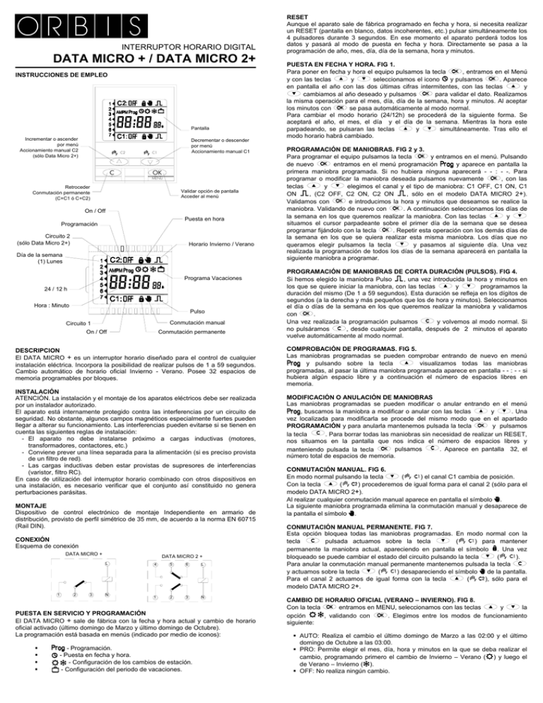
INTERRUPTOR HORARIO DIGITAL DATA MICRO + / DATA MICRO 2+ INSTRUCCIONES DE EMPLEO Pantalla Incrementar o ascender por menú Accionamiento manual C2 (sólo Data Micro 2+) C2 C Decrementar o descender por menú Accionamiento manual C1 C1 OK MENU Retroceder Conmutación permanente (C+C1 ó C+C2) Validar opción de pantalla Acceder al menú On / Off Puesta en hora Programación Circuito 2 (sólo Data Micro 2+) Horario Invierno / Verano Día de la semana (1) Lunes Programa Vacaciones 24 / 12 h Hora : Minuto Pulso Conmutación manual Circuito 1 On / Off Conmutación permanente DESCRIPCION El DATA MICRO + es un interruptor horario diseñado para el control de cualquier instalación eléctrica. Incorpora la posibilidad de realizar pulsos de 1 a 59 segundos. Cambio automático de horario oficial Invierno - Verano. Posee 32 espacios de memoria programables por bloques. INSTALACIÓN ATENCIÓN. La instalación y el montaje de los aparatos eléctricos debe ser realizada por un instalador autorizado. El aparato está internamente protegido contra las interferencias por un circuito de seguridad. No obstante, algunos campos magnéticos especialmente fuertes pueden llegar a alterar su funcionamiento. Las interferencias pueden evitarse si se tienen en cuenta las siguientes reglas de instalación: - El aparato no debe instalarse próximo a cargas inductivas (motores, transformadores, contactores, etc.) - Conviene prever una línea separada para la alimentación (si es preciso provista de un filtro de red). - Las cargas inductivas deben estar provistas de supresores de interferencias (varistor, filtro RC). En caso de utilización del interruptor horario combinado con otros dispositivos en una instalación, es necesario verificar que el conjunto así constituido no genera perturbaciones parásitas. MONTAJE Dispositivo de control electrónico de montaje Independiente en armario de distribución, provisto de perfil simétrico de 35 mm, de acuerdo a la norma EN 60715 (Rail DIN). CONEXIÓN Esquema de conexión DATA MICRO + DATA MICRO 2 + L 1 2 3 N 4 5 6 L 1 2 3 N PUESTA EN SERVICIO Y PROGRAMACIÓN El DATA MICRO + sale de fábrica con la fecha y hora actual y cambio de horario oficial activado (último domingo de Marzo y último domingo de Octubre). La programación está basada en menús (indicado por medio de iconos): - Programación. - Puesta en fecha y hora. - Configuración de los cambios de estación. - Configuración del periodo de vacaciones. RESET Aunque el aparato sale de fábrica programado en fecha y hora, si necesita realizar un RESET (pantalla en blanco, datos incoherentes, etc.) pulsar simultáneamente los 4 pulsadores durante 3 segundos. En ese momento el aparato perderá todos los datos y pasará al modo de puesta en fecha y hora. Directamente se pasa a la programación de año, mes, día, día de la semana, hora y minutos. PUESTA EN FECHA Y HORA. FIG 1. Para poner en fecha y hora el equipo pulsamos la tecla , entramos en el Menú y seleccionamos el icono y pulsamos . Aparece y con las teclas y en pantalla el año con las dos últimas cifras intermitentes, con las teclas cambiamos al año deseado y pulsamos para validar el dato. Realizamos la misma operación para el mes, día, día de la semana, hora y minutos. Al aceptar los minutos con se pasa automáticamente al modo normal. Para cambiar el modo horario (24/12h) se procederá de la siguiente forma. Se aceptará el año, el mes, el día y el día de la semana. Mientras la hora este y simultáneamente. Tras ello el parpadeando, se pulsaran las teclas modo horario habrá cambiado. PROGRAMACIÓN DE MANIOBRAS. FIG 2 y 3. Para programar el equipo pulsamos la tecla y entramos en el menú. Pulsando entramos en el menú programación y aparece en pantalla la de nuevo primera maniobra programada. Si no hubiera ninguna aparecerá - - : - -. Para , con las programar o modificar la maniobra deseada pulsamos nuevamente teclas y elegimos el canal y el tipo de maniobra: C1 OFF, C1 ON, C1 , (C2 OFF, C2 ON, C2 ON , sólo en el modelo DATA MICRO 2+). ON Validamos con e introducimos la hora y minutos que deseamos se realice la maniobra. Validando de nuevo con . A continuación seleccionamos los días de y la semana en los que queremos realizar la maniobra. Con las teclas situamos el cursor parpadeante sobre el primer día de la semana que se desea . Repetir esta operación con los demás días de programar fijándolo con la tecla la semana en los que se quiera realizar esta misma maniobra. Los días que no queramos elegir pulsamos la tecla y pasamos al siguiente día. Una vez realizada la programación de todos los días de la semana aparecerá en pantalla la siguiente maniobra a programar. PROGRAMACIÓN DE MANIOBRAS DE CORTA DURACIÓN (PULSOS). FIG 4. , una vez introducida la hora y minutos en Si hemos elegido la maniobra Pulso y programamos la los que se quiere iniciar la maniobra, con las teclas duración del mismo (De 1 a 59 segundos). Esta duración se refleja en los dígitos de segundos (a la derecha y más pequeños que los de hora y minutos). Seleccionamos el día o días de la semana en los que queremos realizar la maniobra y validamos con . y volvemos al modo normal. Si Una vez realizada la programación pulsamos , desde cualquier pantalla, después de 2 minutos el aparato no pulsáramos vuelve automáticamente al modo normal. COMPROBACIÓN DE PROGRAMAS. FIG 5. Las maniobras programadas se pueden comprobar entrando de nuevo en menú y pulsando sobre la tecla visualizamos todas las maniobras programadas, al pasar la última maniobra programada aparece en pantalla - - : - - si hubiera algún espacio libre y a continuación el número de espacios libres en memoria. MODIFICACIÓN O ANULACIÓN DE MANIOBRAS Las maniobras programadas se pueden modificar o anular entrando en el menú , buscamos la maniobra a modificar o anular con las teclas y . Una vez localizada para modificarla se procede del mismo modo que en el apartado y pulsamos PROGRAMACIÓN y para anularla mantenemos pulsada la tecla . Para borrar todas las maniobras sin necesidad de realizar un RESET, la tecla nos situamos en la pantalla que nos indica el número de espacios libres y pulsamos . Aparece en pantalla 32, el manteniendo pulsada la tecla número total de espacios de memoria. CONMUTACIÓN MANUAL. FIG 6. En modo normal pulsando la tecla ( ) el canal C1 cambia de posición. Con la tecla ( ) procederemos de igual forma para el canal 2 (sólo para el modelo DATA MICRO 2+). Al realizar cualquier conmutación manual aparece en pantalla el símbolo . La siguiente maniobra programada elimina la conmutación manual y desaparece de la pantalla el símbolo . CONMUTACIÓN MANUAL PERMANENTE. FIG 7. Esta opción bloquea todas las maniobras programadas. En modo normal con la tecla pulsada actuamos sobre la tecla ( ) para mantener permanente la maniobra actual, apareciendo en pantalla el símbolo . Una vez bloqueado se puede cambiar el estado del circuito pulsando la tecla ( ). Para anular la conmutación manual permanente mantenemos pulsada la tecla ( ) desapareciendo el símbolo de la pantalla. y actuamos sobre la tecla ( ), sólo para el Para el canal 2 actuamos de igual forma con la tecla modelo DATA MICRO 2+. CAMBIO DE HORARIO OFICIAL (VERANO – INVIERNO). FIG 8. entramos en MENU, seleccionamos con las teclas y la Con la tecla opción , validando con . Elegimos entre los modos de funcionamiento siguiente: AUTO: Realiza el cambio el último domingo de Marzo a las 02:00 y el último domingo de Octubre a las 03:00. PRO: Permite elegir el mes, día, hora y minutos en la que se deba realizar el cambio, programando primero el cambio de Invierno – Verano ( ) y luego el de Verano – Invierno ( ). OFF: No realiza ningún cambio. PROGRAMA DE VACACIONES. FIG 9. Esta posibilidad permite mantener en la posición OFF los circuitos durante un periodo de hasta 99 días. Transcurrido este tiempo se restablece la programación. Si el usuario valida 0 días, el periodo de vacaciones se cancelará y el equipo funcionará de forma normal. Si se valida un número de vacaciones distinto de 0, el equipo entrará en modo vacaciones en ese mismo instante, es decir, los relés pasarán a OFF y no se ejecutará ninguna maniobra programada. Si el número de vacaciones es 1, dicho periodo durará desde el instante actual, hasta las 23:59:59 de hoy. Si el número es 2, el periodo durará lo que queda de hoy más todo el día de mañana. Y así sucesivamente. Durante el tiempo que el aparato está en vacaciones aparece en pantalla el símbolo . Lámparas incandescentes Fluorescentes Halógenas baja tensión Halógenas (230 V.) Lámparas bajo consumo Downlights Leds Consumo propio Contacto: Precisión de marcha: Variación de la precisión con la Tª Reserva de marcha Tipo de acción: Clase y estructura del software Espacios de Memoria: Nº de canales Tipos de maniobras. Precisión de maniobra: Tª de funcionamiento: Tª transporte y almacenamiento Situación de contaminación: Grado de protección: Clase de protección: Temperatura para ensayo de bola Tapa acceso al teclado Conexión Dimensiones de la evolvente DIMENSIONES 88 35 Según indicación en el aparato ± 10 % µ 2 x 16 (10) A/ 250 V~ 3000 W 1200 VA 2000 VA 3000 W 600 VA 400 VA 600 VA 7,3 VA (1,2 W) AgSnO2 conmutado ± 1s/ día a 23 ºC ± 0,15 s/ Cº / 24 h 4 años (sin conexión a red) DATA MICRO +: 1B.1S. 1T. 1U. DATA MICRO 2+: 1S. 1T. 1U Clase A 32 DATA MICRO +: 1 DATA MICRO 2+: 2 ON, OFF, PULSOS (de 1 a 59 segundos) ±1s -10 ºC a +45 ºC -20 ºC a +60 ºC 2 IP 20 según EN 60529 II en montaje correcto + 75 ºC para 21.2.5 Precintable Mediante borne de agujero para conductores de sección máxima 4 mm2 2 módulos DIN (35 mm). 65 60 45 CARACTERISTICAS TÉCNICAS Alimentación Tolerancia Poder de ruptura Cargas máximas recomendadas (N/A): 05/06.2013 A016.17.52570 ORBIS TECNOLOGIA ELECTRICA, S.A. Lérida, 61 E-28020 MADRID Teléfono: +34 91 5672277; Fax: +34 91 5714006 E-mail: info@ orbis.es http://www.orbis.es DIGITAL TIME SWITCH DATA MICRO + / DATA MICRO 2+ OPERATING INSTRUCTIONS Display Increment or move up in menu Circuit C2 override (only Data Micro 2 +) C2 C Decrement or move down in menu Circuit C1 override C1 OK MENU Move back in menu Permanent override (C+C1 ó C+C2) Confirms the selection Starts menu On / Off Clock setting Programming Circuit 2 (only Data Micro 2 +) Summer / Winter time Day of the week (1) Monday Holidays program AM / PM mode Hour : Minute Pulse Override Circuit 1 On / Off Permanent overrride DESCRIPTION DATA MICRO + is a time switch designed to control any electrical installation. Includes pulse programming from 1 to 59 seconds and up to 32 block memory spaces. Automatic winter – summer official time adjustment. INSTALLATION ATTENTION: Electrical devices must be installed and assembled by authorized installer. VERY IMPORTANT: This time switch is protected internally against interference by a safety device. However, particularly strong electromagnetic fields may alter its operation. Such interference can be avoided by adhering to the following recommendations during installation: - The device should not be installed near inductive loads (motors, transformers, contactors, etc) - A separate power line is recommended (equipped with a network filter if necessary) - Inductive loads should be equipped with interference suppressors (varistor, RC filter) If the time switch is to be used in combination with other devices in an installation, it is necessary to verify that no parasitic disturbances will be caused by the group. MOUNTING: Electronic control device for independent installation in distribution cabinet fitted with symmetrical 35 mm profile in accordance with the standard EN 60715 (DIN Rail EN 60715 (Rail DIN). CONNECTION: Connect according with the following schema: DATA MICRO + 1 2 3 DATA MICRO 2 + L 4 5 6 L N 1 2 3 N STARTING UP AND PROGRAMMING DATA MICRO + is already programmed with current date and time, and with the official automatic winter – summer official time adjustment activated (last Sunday in March and last Sunday in October). Programming is based in menus (indicated by icons): • - Programming. - Clock setting. • - Winter / summer official time change. • - Holidays period programming. • RESET Although the clock of the device is already programmed, if a RESET is needed (blank display, inconsistent data, etc), press at the same time the four keys during 3 seconds. In this moment, the device loses all data and goes to clock setting mode, directly to program year, month, day, day of the week, hour and minutes. CLOCK SETTING. FIG 1. to access to the Menu and with keys and For clock setting, press key select icon and press . Display shows the year with the last two figures and and validate it with key blinking; update the year by pressing keys . The same operation should be made to update month, day, day of the week, hour , it automatically goes to normal mode. and minutes. By accepting minutes with To change the time mode (24h/12h am-pm) proceed as follows: accept year, month, day and day of the week; while hour is blinking, press and at the same time. After that, the time mode has change. PROGRAMMING. FIG 2 and 3. To program the device, press to enter to the menu. By pressing again the menu is entered and the display shows the first programmed switching. If no switching is programmed then - - : - - is shown. To program or edit the desired switching press again, with keys and select the circuit and type of switching: C1 OFF, C1 ON, C1 ON , (C2 OFF, C2 ON, C2 ON only in model and introduce hour and minutes desired, DATA MICRO 2+). Validate with . Then select the days of the week that the switching has to validating then with operate. With keys and place the blinking cursor on the first day of the . Repeat this week that the switching has to operate and then fix it by pressing sequence with the other days of the week when the switching has to operate. For the days not desired, press to go down to the next day. After programming all the days of the week, the display will show the next switching to program. SHORT TIME SWITCHING (PULSE) PROGRAMMING. FIG 4. If the selected switching is a Pulse , after introducing hour and minutes when the and to program the length of the pulse (from 1 to pulse starts, use keys 59 seconds). This length is shown in the digits of seconds (situated at the right side and smaller than the digits of hours and minutes). Select the day(s) of the week when the switching has to be programmed and validate with . After that, press to come back to normal mode. If is not pressed, being in any mode, after two minutes, the device returns to normal mode. VIEWING PROGRAMMED SWITCHING. FIG 5. The programmed switching can be checked by entering again in menu and all the switching are shown in display, and after the last one, the pressing key display shows - - : - -, if there is any free space and then it shows the number of free spaces. EDITING OR DELETING SWITCHING Programmed switching can be edited or deleted in menu , selecting with keys or the switching to be edited or deleted. To edit it, proceed as in clause PROGRAMMING and to delete it, keep pressing key and then press key . To delete all the switching without using RESET, go to the point where the display and then press key shows the free spaces of memory, keep pressing key . The display will show 32, the total free memory spaces. MANUAL OVERRIDE. FIG 6. ( ), circuit C1 is activated or deactivated. In normal mode, pressing key ( ) (only in DATA MICRO 2+). The same for circuit C2 by using key If any manual override is executed, it is represented in display by symbol . The next programmed switching cancels the manual override and the symbol disappear from the display. PERMANENT OVERRIDE. FIG 7. This option blocks all the programmed switching. In normal mode, keep pressing key and then press key ( ) to activate the permanent position of circuit; this situation is indicated in display with symbol . After that, the state of the circuit can be changed by pressing key ( ). and then press key To cancel permanent override keep pressing key ( ), symbol disappear from display. The same for circuit C2 using key ) only in DATA MICRO 2+. ( WINTER / SUMMER OFFICIAL TIME CHANGE. FIG 8. Enter MENU by pressing key ; select option using keys . There are the three following working modes: validate with and , AUTO: The clock is automatically changed on the last Sunday in March al 02:00 and the last Sunday in October at 03:00. PRO: Allows to choose the date and time for the time change, programming first the winter – summer change ( ) and then the summer – winter change ( ). OFF: No time change will be made HOLIDAY PROGRAM. FIG 9. This function allows deactivating the circuits during a period of time up to 99 days. After that, the programming continues as usual. If user validates 0 days, the holiday period is cancelled and the device will work in a normal way. If user validates a number of days different than 0, the device starts immediately, so relays switch to OFF and programmed switching will not execute. If the validated number of days is 1, the holiday period will finish at 23:59:59 of the same day than validation. If the validation number of days is 2, the holiday period will finish next day. And so on. Display shows symbol during the holiday period. TECHINCAL FEATURES Voltage rating Tolerance Breaking power Maximum recommended loads (N/O): Incandescent lamps: Fluorescent lamps Low voltage halogen lamps Halogens (230 V) Low-consumption lamps Downlights Leds Self-consumption Contact Operational accuracy Variation of accuracy with temp. Running reserve Type of action Software class and structure Memory slots Nº of channels Types of operation Operating precision Operating temperature Transport and storage Temp Contamination situation Protection degree Protection class Ball test temperature Keypad accesses cover Connection Casing dimensions As indicated on the unit ± 10% µ 2x16 (10) A / 250 V~ 3000 W 1200 VA 2000 VA 3000 W 600 VA 400 VA 600 VA 7.3 VA (1.2 W) AgSnO2 switched ± 1 s/day at 23 ºC ± 0.15 s / ºC / 24 h 4 years (without mains supply connection) DATA MICRO+: 1B, 1S, 1T, 1U DATA MICRO 2+: 1S, 1T, 1U Class A 32 DATA MICRO +: 1 DATA MICRO 2+: 2 ON; OFF PULSE: from 1 to 59 seconds ±1s -10 ºC to +45 ºC -20 ºC to +60 ºC 2 IP 20 as per EN 60529 II in proper assembly + 75 ºC for 21.2.5 Lockable By means of needle post for maximum cable section of 4 mm² 2 DIN modules (35 mm) DIMENSIONS 65 60 45 88 35 05/06.2013 A016.17.52821 ORBIS TECNOLOGIA ELECTRICA, S.A. Lérida, 61 E-28020 MADRID Teléfono: +34 91 5672277; Fax: +34 91 5714006 E-mail: info@ orbis.es http://www.orbis.es INTERRUPTEUR HORAIRE NUMÉRIQUE DATA MICRO + et DATA MICRO 2+ INSTRUCTIONS D’EMPLOI Écran Augmenter ou monter dans le menu Actionnement manuel C2 (Seulement Data Micro 2) C2 Diminuer ou descendre dans le menu Actionnement manuel C1 C1 C OK MENU Revenir en arrière Commutacion permanente (C+C1 ou C+C2) Valider une option à l'écran Accéder au menu On / Off Mise à l'heure Programmation Circuit 2 (Seulement Data Micro 2) Heure d'Hiver / Été Jour de la semaine (1) Lundi Programme Vacances 24 / 12 h Heure : Minutes Pulsation Commutation manuelle Circuit 1 On / Off Commutation permanente DESCRIPTION Le DATA MICRO + est un interrupteur horaire conçu pour le contrôle de n’importe quelle installation électrique. Il offre la possibilité de réaliser des pulsations de 1 à 59 secondes. Changement automatique de l’heure officielle Hiver - Été. Il possède 32 espaces de mémoire programmables par blocs. INSTALLATION ATTENTION. L’installation et le montage des appareils électriques doivent être réalisés par un installateur agréé. L'appareil est internement protégé contre les interférences par un circuit de sécurité. Toutefois, certains champs magnétiques particulièrement forts peuvent arriver à altérer son fonctionnement. Les interférences peuvent être évitées en respectant les règles d’installation suivantes : - L’appareil ne doit pas être installé à proximité de charges inductives (moteurs, transformateurs, contacteurs, etc.) - Il convient de prévoir une ligne séparée pour l’alimentation (si nécessaire dotée d’un filtre de réseau). - Les charges inductives doivent être munies de suppresseurs d’interférences (varistor, filtre RC). En cas d’utilisation de l’interrupteur horaire combiné avec d’autres dispositifs dans une installation, il est nécessaire de vérifier que l’ensemble ainsi constitué ne génère pas de perturbations parasites. MONTAGE : Dispositif électronique de commande de montage independant en armoire de distribution dotée d’un profil symétrique de 35 mm, conformément à la norme EN 60175 (rail DIN). CONNEXION Schéma de connexion DATA MICRO + 1 2 3 DATA MICRO 2 + L 4 5 6 L N 1 2 3 N MISE EN SERVICE ET PROGRAMMATION Le DATA MICRO + sort d’usine avec la date et l’heure actuelles, et le changement d’heure officiel activé (dernier dimanche de mars et dernier dimanche d’octobre). La programmation se base sur des menus (indiqués par des icones) : • - Programmation. - Réglage date et heure. • - Configuration des changements de saison. • - Configuration de la période de vacances. • RÉINITIALISATION Bien que l’appareil sorte d’usine avec la date et l’heure programmées, si vous avez besoin de réaliser une RÉINITIALISATION (écran en blanc, données incohérentes, etc.), appuyez à la fois sur les 4 boutons pendant 3 secondes. L’appareil perdra alors toutes les données et passera au mode de réglage de la date et de l’heure. Il passe directement à la programmation de l’année, du mois, du jour, du jour de la semaine, de l’heure et des minutes. RÉGLAGE DE LA DATE ET DE L’HEURE. FIG 1. , entrez dans Pour régler la date et l’heure de l’appareil, appuyez sur la touche le menu et, avec les flèches et , sélectionnez l’icone , puis appuyez sur . L’année apparaît à l’écran avec les deux derniers chiffres qui clignotent, avec les touches et , indiquez l’année, puis appuyez sur pour valider. Réalisez la même opération pour le mois, le jour, le jour de la semaine, l’heure et les , vous passez minutes. Lorsque vous validez les minutes avec automatiquement au mode normal. Pour changer le mode horaire (24/12h), procédez comme suit. Validez l’année, le mois, le jour et le jour de la semaine et, pendant que l’heure clignote, appuyez à la et pour changer le mode horaire. fois sur les touches PROGRAMMATION DE MANŒUVRES. FIG 2 et 3. Pour programmer l’équipement, appuyez sur la touche pour entrer dans le menu. Appuyez à nouveau sur pour entrer dans le menu de programmation . La première manœuvre programmée apparaît à l’écran. S’il y en a aucune vous verrez : - - : - - . Pour programmer ou modifier la manœuvre de votre choix, et choisissez, avec les touches et , le canal appuyez à nouveau sur et le type de manœuvre : C1 OFF, C1 ON, C1 ON ,(C2 OFF, C2 ON, C2 ON , seulement sur le modèle DATA MICRO 2+). Validez avec et indiquez l’heure et les minutes de réalisation de la manœuvre. Validez à nouveau avec , puis sélectionnez les jours de la semaine où vous souhaitez réaliser la manœuvre. Avec les touches et , placez le curseur clignotant sur le premier jour de la . semaine que vous souhaitez programmer en le sélectionnant avec la touche Répétez cette opération pour les autres jours de la semaine où vous souhaitez réaliser cette même manœuvre. Lorsque vous êtes sur un jour que vous ne souhaitez pas sélectionner, appuyez sur la touche pour passer au jour suivant. Une fois la programmation de tous les jours de la semaine terminée, la manœuvre suivante à programmer s’affiche à l’écran. PROGRAMMATION DE MANŒUVRES DE COURTE DURÉE (PULSATIONS). FIG 4. Si vous avez choisi la manœuvre Pulsation , après avoir indiqué l’heure et les et minutes où vous souhaitez commencer la manœuvre, avec les touches , programmez la durée de celle-ci (de 1 à 59 secondes). Cette durée est affichée par les chiffres des secondes (à droite et plus petits que ceux de l’heure et des minutes). Sélectionnez le ou les jours de la semaine où vous souhaitez réaliser la manœuvre, puis validez avec . Une fois la programmation terminée, appuyez sur pour revenir au mode normal. , depuis n’importe quel écran, l’appareil retourne Si vous n’appuyez pas sur automatiquement au mode normal au bout de 2 minutes. VÉRIFICATION DES PROGRAMMES. FIG 5. Les manœuvres programmées peuvent être vérifiées en entrant à nouveau dans le et en appuyant sur la touche pour afficher toutes les manœuvres menu programmées. Après la dernière manœuvre programmée l’écran affiche - - : - -, s’il reste des espaces libres suivi du nb. d’espaces libres en mémoire. MODIFICATION OU ANNULATION DE MANŒUVRES Les manœuvres programmées peuvent être modifiées ou annulées en entrant dans le menu et en cherchant la manœuvre à modifier ou à annuler avec les touches et . Une fois localisée, pour la modifier procédez de la même façon que dans la section PROGRAMMATION, et pour l’annuler maintenez la touche enfoncée et appuyez sur la touche . Pour effacer toutes les manœuvres sans réaliser une RÉINITIALISATION, rendez-vous dans l’écran indiqué par le nb. enfoncée, appuyez sur . d’espaces libres et, en maintenant la touche L’écran affiche 32, le nombre total d’espaces de mémoire. COMMUTATION MANUELLE. FIG 6. ( ), le canal C1 En mode normal, quand vous appuyez sur la touche change de position. Avec la touche ( ), procédez de la même façon pour le canal 2 (C2) (seulement pour le modèle DATA MICRO 2+). Lorsque vous réalisez une commutation manuelle, l’écran affiche le symbole . La manœuvre programmée suivante élimine la commutation manuelle, et le symbole disparaît de l’écran. COMMUTATION MANUELLE PERMANENTE. FIG 7. Cette option bloque toutes les manœuvres programmées. En mode normal avec la enfoncée, appuyez sur la touche ( ) pour maintenir de façon touche apparaît à l’écran. Une fois permanente la manœuvre actuelle. Le symbole bloqué, vous pouvez changer l’état du circuit en appuyant sur la touche ( ). Pour annuler la commutation manuelle permanente, maintenez enfoncée la touche et appuyez sur la touche ( ). Le symbole disparaît de l’écran. Pour le canal 2 procédez de la même façon avec la touche ( ), seulement pour le modèle DATA MICRO 2+. CHANGEMENT D’HEURE OFFICIEL (ÉTÉ – HIVER). FIG 8. , entrez dans le menu, sélectionnez avec les touches et Avec la touche l’option , puis validez avec . Choisissez un des modes de fonctionnement suivants : AUTO : réalise le changement le dernier dimanche de mars à 02:00 et le dernier dimanche d’octobre à 03:00. PRO : permet de choisir le mois, le jour, l’heure et les minutes où le changement doit être réalisé, en programmant d’abord le changement Hiver – Été ( ), puis le changement Été – Hiver ( ). OFF: aucun changement n’est réalisé. PROGRAMME DE VACANCES. FIG 9. Cette option permet maintenir dans la position OFF les circuits pendant une période de jusqu’à 99 jours. Une fois ce temps écoulé, la programmation est rétablie. Si l’utilisateur valide 0 jours, la période de vacances sera annulée et l’équipement fonctionnera de façon normale. Si un chiffre de vacances différent de 0 est indiqué, l’équipement entrera en mode vacances à cet instant précis, c’est-à-dire que les relais passeront à OFF et qu’aucune manœuvre programmée ne sera réalisée. Si le chiffre de vacances est 1, cette période durera depuis l’instant actuel, jusqu’à 23:59:59 de ce même jour. Si le chiffre est 2, la période durera le reste de la journée, plus toute la journée suivante, et ainsi de suite. Pendant tout le temps où l’appareil est en mode vacances, l’écran affiche le symbole . CARACTÉRISTIQUES TECHNIQUES Alimentation Selon indications sur l’appareil Tolérance ± 10 % Pouvoir de rupture : μ 2x16 (10) A / 250 V~ Charges maximales recommandées (N/O): Lampes incandescentes 3000 W Fluorescentes 1200 VA Halogènes basse tension 2000 VA Halogènes (230 V) 3000 W Lampes faible consommation 600 VA Downlights 400 VA Lamp Led 600 VA Consommation propre Contact : Précision de marche Variation de la précision avec la Tº Réserve de marche Type d’action Classe et structure du logiciel Espaces de mémoire Nb. de canaux Types de manœuvre Précision de la manœuvre Tº de fonctionnement Tº de transport et de stockage Situation de pollution Type de protection Classe de protection Température pour l’essai bille Couvercle d’accès au clavier Connexion Dimensions de l’enveloppe 7,3 VA (1,2 W) AgSnO2 commuté ± 1 s/jour à 23 ºC ±0,15 s/ºC/24 h 4 ans (sans reccordement électrique) DATA MICRO + 1B, 1S, 1T, 1U DATA MICRO 2+ 1S, 1T, 1U Classe A 32 DATA MICRO + : 1 DATA MICRO 2+ : 2 ON/OFF/.PULSATION(De 1 a 59 s) ±1s -10 ºC à +45 ºC -20 ºC à +60 ºC 2 IP 20 selon EN 60529 II en montage correct + 75 ºC (2.1.25) Hermétique Grâce à une borne à trou pour conducteurs à section maximale 4 mm² 2 modules DIN (35 mm) DIMENSIONS 65 60 45 88 35 05/07.2013 A016.17.52844 ORBIS TECNOLOGIA ELECTRICA, S.A. Lérida, 61 E-28020 MADRID Téléphone : +34 91 5672277 ; Fax : +34 91 5714006 Courriel : info@ orbis.es http://www.orbis.es DIGITALE ZEITSCHALTUHR DATA MICRO + und DATA MICRO 2+ BEDIENUNGSANLEITUNG Display Menügesteuert erhöhen / erniedrigen Manuelle Betätigung C2 (Nur für Data Micro 2) C2 C Menügesteuert erhöhen / erniedrigen Manuelle Betätigung C1 C1 OK MENU Zurük Dauernde Umschaltung (C+C1 oder C+C2) Bestätigen der angezeigten Funktion Menüaufruf On / Off Stellen Uhrzeit Programmierung Kreis 2 (Nur Data Micro 2) Sommer- / Winterzeit Wochentag (1) Montag Urlaubsprogramm 24 / 12 h Stunden: Minuten Impuls Uhmschaltung manuell Kreis 1 On / Off Ständige Umschaltung BESCHREIBUNG DATA MICRO + ist eine Zeitschaltuhr zur Steuerung elektrischer Anlagen. Sie beinhaltet die Möglichkeit zur Abgabe von Impulsen mit einer Dauer von 1 bis 59 s. Automatische Umschaltung zwischen Sommer- und Winterzeit. Die Zeitschaltuhr verfügt über 32 in Blöcken programmierbare Speicherplätze. INSTALLATION ACHTUNG. Installation und Montage elektrischer Geräte dürfen nur durch zugelassene Installateure erfolgen. Das Gerät ist intern mit Hilfe einer Schutzschaltung gegen Interferenzen geschützt. Trotz dieser Schutzmaßnahmen können sehr starke Magnetfelder die Funktion beeinträchtigen. Interferenzen lassen sich unter Beachtung folgender Installationsregeln vermeiden: Das Gerät nicht in der Nähe induktiver Lasten (Motoren, Transformatoren, Schütze usw.) montieren. Einspeisung über einen getrennten Netzstromkreis (bei Bedarf mit Netzfilter). Induktive Lasten müssen mit Schutzeinrichtungen zum Abbau von Überspannungen ausgerüstet werden (Varistoren, RC-Filter). Bei Einsatz der Zeitschaltuhr zusammen mit anderen Geräten in einer Anlage muss geprüft werden, ob hierdurch Störsignale emittiert werden. MONTAGE: Elektronisches Kontrollgerät für den unabhängigen Einbau im Schaltschrank mittels symmetrischem 35mm-Profil gemäß der Norm EN 60715 (Hutschiene). ANSCHLUSS Anschlussschema DATA MICRO + 1 2 3 DATA MICRO 2 + L 4 5 6 L N 1 2 3 N INBETRIEBSETZUNG UND PROGRAMMIERUNG Die Zeitschaltuhr DATA MICRO + wird werksseitig auf die aktuellen Werte von Uhrzeit und Datum sowie die offizielle Umschaltung zwischen Sommer- und Winterzeit (letzter Sonntag im März und letzter Sonntag im Oktober) gestellt. Die Programmierung erfolgt mit Hilfe von Menüs (durch Schaltsymbole dargestellt). • - Programmierung. - Datum und Uhrzeit stellen. • - Konfigurieren der Umschaltung Sommer-Winterzeit. • - Konfigurieren der Urlaubsperiode. • RESET Die Schaltuhr verlässt das Werk mit aktuellen Werten für Datum und Uhrzeit. Falls jedoch ein RESET erforderlich wird (Display ohne Anzeige, nicht kohärente Daten usw.), betätigen Sie die vier Tasten gleichzeitig für 3 Sekunden. Damit werden alle Daten gelöscht und das Gerät geht in den Modus zur Einstellung von Datum und Uhrzeit über. Danach ist die direkte Eingabe von Jahr, Monat, Tag, Wochentag, Stunden und Minuten möglich. STELLEN VON DATUM UND UHRZEIT. FIG 1. Zum Stellen von Datum und Uhrzeit die Taste betätigen. Das Menü wird geöffnet, wählen Sie mit den Tasten und das Symbol und bestätigen . Auf dem Display wird das Jahr mit den letzten beiden Stellen blinkend Sie mit angezeigt. Ändern mit den Tasten und , Bestätigen der Eingabe mit . Die gleichen Operationen für Monat, Tag, Wochentag, Stunden und Minuten wiederholen. Nach Bestätigen der Minuten mit wird auf den Normalbetrieb umgeschaltet. Die Umschaltung der Anzeige (24/12h) wird wie folgt vorgenommen: Bestätigung von Jahr, Monat, Tag und Wochentag. Die Tasten und gleichzeitig drücken, während die Stundenanzeige blinkt. Damit erfolgt die Umschaltung zwischen beiden Anzeigearten. PROGRAMMIERUNG VON SCHALTVORGÄNGEN. FIG 2 und 3. Zur Programmierung des Geräts die Taste drücken, damit wird das Menü drücken, damit wird das Menü Programmieren geöffnet. Nochmals aktiviert, auf dem Display wird der erste Schaltvorgang angezeigt. Ist kein Schaltvorgang programmiert, wird - - : - - . angezeigt. Zum Programmieren oder betätigen, mit den Tasten und Ändern des Schaltvorgangs erneut , (C2 den Kanal und die Art des Schaltvorgangs wählen: C1 OFF, C1 ON, C1 ON OFF, C2 ON, C2 ON , nur für das Modell DATA MICRO 2+). Mit bestätigen und die Uhrzeit mit Stunden und Minuten eingeben, zu welcher der Schaltvorgang bestätigen. Anschließend werden die Wochentage auszuführen ist. Erneut mit ausgewählt, an denen dieser Schaltvorgang ausgeführt werden soll. Mit den Tasten und den blinkenden Cursor auf den ersten zu programmierenden bestätigen. Diesen Vorgang mit den Wochentag führen und mit der Taste übrigen Wochentagen wiederholen, an denen der Schaltvorgang auszuführen ist. Die Tage, für die keine Programmierung gewünscht wird, mit der Taste überspringen, es wird der nächste Tag angezeigt. Nach Abschluss der Programmierung für alle Wochentage wird auf dem Display der nächste Schaltvorgang angezeigt. PROGRAMMIERUNG VON SCHALTVORGÄNGEN KURZER DAUER (IMPULSE). FIG 4. Bei Auswahl von Impuls wird nach Eingabe der Uhrzeit in Stunden und Minuten die Impulslänge (1 bis 59 s) festgelegt. Die Impulsdauer wird in den Stellen entsprechend der Sekundenanzeige wiedergegeben (kleinere Ziffern, rechts von den Stellen für Stunden und Minuten). Anschließend den oder die Wochentage auswählen, an denen dieser Schaltvorgang ausgeführt werden soll und mit betätigen, damit erfolgt die bestätigen. Nach Abschluss der Programmierung Rückkehr in den Normalbetrieb. Wird in einem beliebigen Bildschirm die Taste nicht gedrückt, kehrt das Gerät nach 2 Minuten automatisch in den Normalbetrieb zurück. ÜBERPRÜFUNG DER PROGRAMMIERUNG. FIG 5. Die programmierten Schaltvorgänge werden durch nochmaliges Aktivieren des überprüft, mit der Taste werden alle programmierten Menüs Schaltvorgänge angezeigt. Nach dem letzten Schaltvorgang erscheint auf dem Display - - : - - , falls noch ein Speicherplatz frei ist, sowie die Anzahl der freien Speicherplätze. ÄNDERN UND LÖSCHEN VON SCHALTVORGÄNGEN. Die programmierten Schaltvorgänge werden im Menü geändert oder gelöscht. und Der zu ändernde oder zu löschende Schaltvorgang wird mit den Tasten ausgewählt. Das Ändern des ausgewählten Schaltvorgangs erfolgt in gleicher Weise wie im Abschnitt PROGRAMMIERUNG beschrieben. Zum Löschen die Taste gedrückt halten und die Taste betätigen. Zum Löschen aller Schaltvorgänge ohne Auslösung eines RESET wie folgt vorgehen: Auf dem Bildschirm mit der Anzeige der freien Speicherplätze die Taste gedrückt halten und die Taste betätigen. Auf dem Display wird 32 angezeigt, entsprechend der Gesamtzahl von Speicherplätzen. MANUELLE SCHALTVORGÄNGE. FIG 6. ( ) betätigen, damit wird der Schaltzustand Im Normalbetrieb die Taste von Kanal C1 geändert. Mit der Taste ( ) in gleicher Weise für Kanal 2 (C2) vorgehen (nur für das Modell DATA MICRO 2+). Nach Ausführung eines beliebigen manuellen Schaltvorgangs wird auf dem Display angezeigt. das Symbol Durch den nächsten programmierten Schaltvorgang wird die manuelle Betätigung gelöscht, auf dem Display wird das Symbol angezeigt PERMANENT UMSCHALTUNG AUF MANUELLE SCHALTVORGÄNGE. FIG 7. Mit dieser Option werden alle programmierten Schaltvorgänge blockiert. Im Normalbetrieb die Taste gedrückt halten und die Taste ( ) betätigen, um den aktuellen Schaltvorgang permanent festzuhalten. Auf dem Display wird das Symbol angezeigt. Nach der Blockierung ist es möglich, den Schaltzustand des ( ) zu ändern. betreffenden Kreises durch Betätigen der Taste Zum Löschen der permanenten manuellen Umschaltung die Taste gedrückt ( ) betätigen, das Symbol wird damit gelöscht. Mit halten und die Taste der Taste ( ) in gleicher Weise für Kanal 2 (C2) vorgehen (nur für das Modell DATA MICRO 2+). UMSCHALTUNG SOMMERZEIT – WINTERZEIT. FIG 8. aktivieren, mit den Tasten und die Option Das Menü mit der Taste wählen und mit bestätigen. Damit ist die Auswahl zwischen folgenden Modi möglich: AUTO: Die Umschaltung auf die Sommerzeit erfolgt am letzten Sonntag im März um 02:00 Uhr, die Umschaltung auf die Winterzeit am letzten Sonntag im Oktober um 03:00 Uhr. PRO: Gestattet die Auswahl des Umschaltzeitpunkts in der Form Monat, Tag, Stunde und Minuten, zuerst wird die Umschaltung Winter - Sommer ( ) und danach die Umschaltung Sommer - Winter programmiero ( ). OFF: Es erfolgt keine Änderung. URLAUBSPROGRAMMIERUNG. FIG 9. Mit dieser Programmierung werden alle Kreise für eine Zeitdauer bis maximal 99 Tage auf OFF geschaltet. Nach Ablauf dieser Zeit wird die normale Programmierung wieder hergestellt. Wird der Wert 0 Tage eingegeben, erfolgt keine Umschaltung auf den Urlaubsmodus und das Gerät arbeitet im Normalbetrieb. Wird für die Urlaubsperiode eine von 0 verschiedene Dauer eingegeben, schaltet das Gerät in diesem Moment auf den Urlaubsmodus um, alle Relais werden auf OFF geschaltet und es wird kein programmierter Schaltvorgang ausgeführt. Wird für die Urlaubsperiode 1 Tag eingegeben, dauert diese vom aktuellen Eingabezeitpunkt bis 23:59:59 h des Tags, an dem die Eingabe erfolgt ist. Wird der Wert 2 eingetragen, dauert die Abschaltung entsprechend für den Tag, an dem die Abschaltung erfolgt ist, und den ganzen darauf folgenden Tag, usw. Während der Urlaubsperiode wird auf dem Display des Geräts das Symbol angezeigt . TECHNISCHE DATEN Nennspannung Toleranz Schaltleistung Empfohlene Höchstlasten (N.O): Glühlampen Leuchtstofflampen Niederspannungs-Halogenlampen Halogenlampen (230 V.) Energiesparlampen Downlight LED Lampe Eigenverbrauch Kontakt Ganggenauigkeit Temperaturabhängige Anz.abweichung Gangreserve Schaltart: Softwareklasse und -struktur Speicherplätze: Anzahl Kanäle Art der Schaltvorgänge: Schaltgenauigkeit Betriebstemperatur Transport- und Lagertemperatur Verschmutzungsgrad Schutzart Schutzklasse Temperatur für Kugeldruckprüfung Schutzklappe für Tastenfeld Anschluss Gehäuse Gemäß Geräteangabe ± 10% μ 2x16 (10) A / 250 V~ 3000 W 1200 VA 2000 VA 3000 W 600 VA 400 VA 600 VA 7,3 VA (1,2 W) AgSnO2 Umschaltkontakt ± 1 s/Tag bei 23 ºC ± 0,15 s / ºC / 24 h 4 Jahre mittels(austauschbarer) DATA MICRO + 1B, 1S, 1T, 1U DATA MICRO 2+ 1S, 1T, 1U Klasse A 32 DATA MICRO + : 1 DATA MICRO 2+: 2 ON / OFF / IMPULSE (1 bis 59 s) ± 1 Sekunden -10 ºC bis +45 ºC -20 ºC bis +60 ºC 2 IP 20 nach EN 60529 II bei ordnungsgemäßem Einbau + 75º für 21.2.5 Plombierbar Mittels Buchsenklemme für Kabel mit einem max. Querschnitt von 4 mm² 2 Teilungseinheiten (35 mm) ABMESSUNGEN 65 60 45 88 35 05/07.2013 A016.17.52846 ORBIS TECNOLOGIA ELECTRICA, S.A. Lérida, 61 E-28020 MADRID Telefon: +34 91 5672277; Fax: +34 91 5714006 E-mail: info@ orbis.es http://www.orbis.es INTERRUTTORE ORARIO DIGITALE DATA MICRO + / DATA MICRO 2+ ISTRUZIONI DI IMPIEGO Display Aumentare sul menu Azionamento manuale C2 (solo Data Micro 2) C2 C Disminuire sul menu Azionamento manuale C1 C1 OK MENU Retrocedere Conmutacione manuale permanente (C+C1 o C+C2) OK.Conferma opzione sul display. Accedere a menu On / Off Impostazione data/ora Programmazione Canale 2 (Solo Data Micro 2) Orario invernale/estivo rno della settimana (1) Lunedi Programma vacanze Formato de ora a 12 ore Ora corrente Impulso Conmutazione manuale Canale 1 On / Off Conmutazione manuale permanente DESCRIZIONE Il Data Micro + e’ un’interruttore orario creato per un controllo di una qualsiasi installazione elettrica. Al suo interno ha un programma ad impulsi regolabile da 1 a 59 secondi il cambio dell’ ora legale è automatico e può essere programmato dall’ utente. Programmazioni massime consentite 32 (ON-OFF). INSTALLAZIONE ATTENZIONE: Questo dispositivo elettrico deve essere installato da persona competente. L’apparecchio deve essere installato in un quadro tale da garantire, dopo l’installazione, la inaccessibilità ai morsetti di collegamento. Il dispositivo è protetto contro le interferenze, tuttavia i campi magnetici, specialmente se forti, potrebbero modificare il suo funzionamento. Le interferenze possono essere evitate se si seguono alcune semplici regole: • Evitare installazioni in prossimità di carichi induttivi (teleruttori, trasformatori, etc..). • Prevedere una linea di alimentazione separata (all’occorrenza dotata di filtro di rete). • I carichi induttivi devono essere provvisti di elementi per la soppressione delle interferenze (varistori, filtri RC). • Se l’interruttore orario si usa in combinazione con altri dispositivi in un’installazione, bisogna verificare che il sistema così costituito non generi perturbazioni parassite. Il dispositivo deve essere installato in un armadio di distribuzione avente profilo simmetrico di 35 mm, secondo la norma EN 60715 (Rail DIN). CONNESSIONI Schema di connessione DATA MICRO 2 + DATA MICRO + L 1 2 3 N 4 1 5 2 6 3 L N MESSA IN FUNZIONE Il Data Micro e’ preimpostato dal fabbricante con l’orario reale e con il cambio dell’ ora legale dall’ ultima Domenica di Marzo all’ ultima Domenica di Ottobre. La programmazione preinpostata e’ facilmente sostituibile ed intuitiva a mezzo di simboli: - Programmazione. - Data e ora. - Configurazione del cambio di stagione. - Configurazione del periodo di vacanze. RESET L’Apparato esce dalla fabbrica con data e ora preinpostata. L’ eventuale azzeramento delle funzioni preinpostate verrà eseguito tenendo premuti simultaneamente i 4 pulsanti per circa 3 secondi. IMPOSTAZIONE DATA / ORA. FIG 1. , sul display Per impostare la data e l’ ora tenere premuto il pulsante compariranno i simboli del menù, con la freccia e selezioniamo l’icona . Sul display verra’ visualizzato l’anno con l’ultima cifra e premiamo e cambiamo l’anno desiderato e premiamo lampeggiante e con i tasti per convalidare il dato. Facciamo la stessa operazione per impostare il mese, il giorno, giorno della e la programmazione settimana. ora e minuti e per convalidare premiamo passera’ automaticamente nel modo normale. Per cambiare il modo orario (24/12h) si procedera’ nel seguente modo, confermare l’anno, il mese, il giorno, e il giorno della settimana, mentre l’ora sta lampeggiando premere simultaneamente i tasti e . PROGRAMMAZIONE. FIG 2 y 3. e entriamo nel menú. Per eseguire la programmazione premiamo il pulsante entriamo nel menú programmazione e apparira’ sul Premendo di nuovo display la prima impostazione programmata se non risultera’ nessuna programmazione impostata, apparira’ - - : - - . Per programmare o modificare la , con i tasti freccia e funzione desiderata premiamo nuovamente scegliamo il canale e la funzione C1 OFF, C1 ON, C1 ON ,(C2 OFF, C2 ON, C2 , solo nel modello DATA MICRO 2 +) Convalidiamo con e impostiamo ON l’ora e i minuti . e , a questo punto Selezionare il giorno della settimana con i tasti freccia vedremo il triangolino posto sul lato sinistro del display spostarsi per i giorni della settimana impostati. Ripetere la stessa operazione per impostare altre funzioni confermando la stessa con il tasto . Una volta terminata l’operazione premiamo il tasto per tornare al modo normale. PROGRAMMAZIONE IMPULSO. FIG 4. una volta introdotta l’ora e i minuti Se abbiamo impostato la funzione impulso e , programmeremo la durata dello stesso (da 1 a 59 secondi). con i tasti Una volta terminata l’operazione premiamo il tasto per tornare al modo normale. CONFERMA DI PROGRAMMAZIONE. FIG 5. Le funzioni memorizzate si possono visionare entrando di nuovo nella funzione e premendo il tasto visualizziamo tutte le funzioni impostate, al menu finire apparira’ - - : - -, visualizzando lo spazio libero in memoria. MODIFICHE O ANNULLAMENTO FUNZIONI Le funzioni programmate si possono modificare o annullare entrando nel menu e . impostando la funzione modifica o annulla con i tasti Una volta individuata, per modificarla si procede nello stesso modo nella funzione PROGRAMMAZIONE per annullare teniamo premuto il tasto e premiamo il . Per cancellare tutte le funzioni dobbiamo RESETTARE il tutto. Sul tasto display apparira’ lo spazio libero mantenendo premuti i tasti e visualizzeremo il num 32 che indichera’ lo spazio totale nella memoria . COMMUTAZIONE MANUALE. FIG 6. ( ) il canale C1 cambia di posizione. In modo normale premendo il tasto ( ) procederemo nella stessa maniera per il canale 2 (solo Con la freccia per il modello DATA MICRO 2+). Dopo qualsiasi operazione apparira’ il símbolo . La seguente funzione viene eliminata alla prima commutazione automatica. COMMUTAZIONE MANUALE PERMANENTE. FIG 7. Questa opzione blocca tutte le funzioni programmate.Premendo il tasto e il ( ) apparira’ sul display il simbolo . Per annullare la tasto freccia commutazione manuale si interverràà con la medesima operazione. CAMBIO ORARIO LEGALE. FIG 8. Con il tasto entriamo nel MENU, selezioniamo con i tasti e l’ opzione confermando con . AUTO: Conferma il cambio ora legale dell’ultima Domenica di Marzo alle 02:00 a.m.e l’ultima Domenica di Ottobre alle 03:00 a.m. PRO: Imposta il mese il giorno, l’ora, e i minuti e il cambio di stagione visualizzando per primo il cambio Inverno – Estate ( ) e in secondo luogo Estate – Inverno ( ). OFF: Non effettua nessun cambio. PROGRAMMA VACANZE. FIG 9. Questa possibilita’ permette di mantenere il circuito in posizione OFF durante un periodo di vacanze di 99 giorni. Trascorso questo tempo si ristabilizzera’ la programmazione iniziale. Se sul display apparira’ 0 giorni il periodo di riposo si cancellera’ e il programma torrnera’ in modalita’ normale.Se si imposta un periodo di vacanze uguale a 0 , il dispositivo entrera’ in funzione nel modo vacanze all’istante e le funzioni impostate saranno cancellate. Se il giorno di vacanza e’ 1 il periodo di spegnimento sara’ sino alle 23:59:59 di oggi; se il giorno di vacanza sara’ 2 il periodo di spegnimento sara’ uguale a un giorno piu’ 23:59:59 secondi. Durante questa fase l’apparato restera’ nel programma vacanze visualizzando il simbolo sul display. CARATTERISTICHE TECNICHE Tensione nominale Tolleranza Potere di rottura: Carico massimo raccomandato (N/O): Vedere quanto indicato sul dispositivo ± 10% µ 2x16 (10) A / 250 V~ Lampada incandescenza 3000 W Fluorescenza 1200 VA Alogena bassa tensione 2000 VA Alogena (230 V.) 3000 W Lampada basso consumo (CFL) 600 VA Lampada basso consumo (Downlights) 400 VA Lampada Led 600 VA Autoconsumo Contatto Precisione di funzionamento Variazione della precisione con la Tª Riserva di carica Tipo di azione Classe e struttura del software Numero max programmazioni Nº di canali (relè) Tipi di manovra Precisione operazione Temp. di funzionamento Temp. di trasporto e immagazzinamento Gradi di inquinamento Gradi di protezione Classe di protezione Temperatura di prova con la sfera Coperchio protezione tasti trasparente Collegamenti Dimensioni Massimo 7,3 VA induttivi (1,2 W) AgSnO2 in scambio ± 1 s / giorno a 23 ºC ± 0,15 s / ºC / 24 h 4 anni (nessun collegamento alla rete) DATA MICRO+: 1B, 1S, 1T, 1U DATA MICRO 2+: 1S, 1T, 1U Classe A 32 DATA MICRO +: 1 DATA MICRO 2+: 2 ON/OFF IMPULSO: da 1 a 59 secondi ± 1 secondo -10 ºC a +45 ºC -20 ºC a +60 ºC 2 IP 20 secondo EN60529 II in condizioni di montaggio corrette + 75 ºC per 21.2.5 Piombabile Morsetti a vite per cavi sez. max 4 mm2 2 moduli DIN (35 mm) DIMENSIONI 65 60 45 88 35 05/07.2013 A016.17.52984 ORBIS ITALIA S.p.A. Via L. Da Vinci,9/B Cassina De Pecchi -MITel.- 02/95343454 Fax- 02/9520046 e-mail: info@orbisitalia.it http://www.orbisitalia.it
