instructions for mechanical multidisc clutches 3.2 series
Anuncio
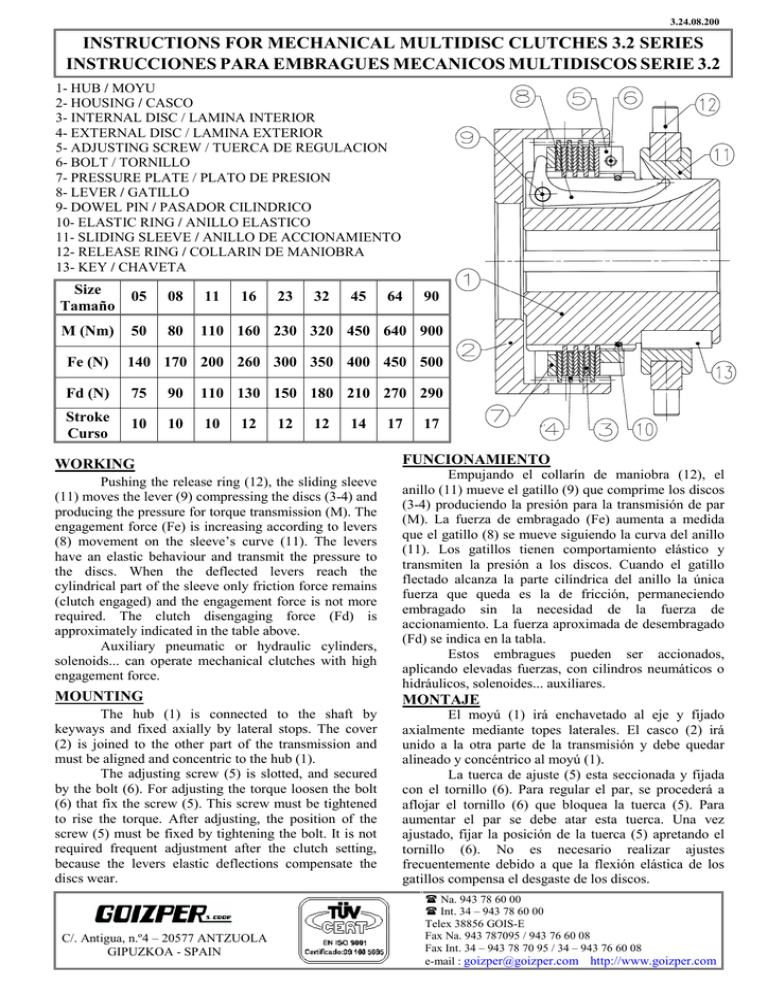
3.24.08.200 INSTRUCTIONS FOR MECHANICAL MULTIDISC CLUTCHES 3.2 SERIES INSTRUCCIONES PARA EMBRAGUES MECANICOS MULTIDISCOS SERIE 3.2 1- HUB / MOYU 2- HOUSING / CASCO 3- INTERNAL DISC / LAMINA INTERIOR 4- EXTERNAL DISC / LAMINA EXTERIOR 5- ADJUSTING SCREW / TUERCA DE REGULACION 6- BOLT / TORNILLO 7- PRESSURE PLATE / PLATO DE PRESION 8- LEVER / GATILLO 9- DOWEL PIN / PASADOR CILINDRICO 10- ELASTIC RING / ANILLO ELASTICO 11- SLIDING SLEEVE / ANILLO DE ACCIONAMIENTO 12- RELEASE RING / COLLARIN DE MANIOBRA 13- KEY / CHAVETA Size Tamaño 05 08 11 M (Nm) 50 80 110 160 230 320 450 640 900 16 23 32 45 64 90 Fe (N) 140 170 200 260 300 350 400 450 500 Fd (N) 75 90 110 130 150 180 210 270 290 Stroke Curso 10 10 10 12 12 12 14 WORKING 17 17 FUNCIONAMIENTO Pushing the release ring (12), the sliding sleeve (11) moves the lever (9) compressing the discs (3-4) and producing the pressure for torque transmission (M). The engagement force (Fe) is increasing according to levers (8) movement on the sleeve’s curve (11). The levers have an elastic behaviour and transmit the pressure to the discs. When the deflected levers reach the cylindrical part of the sleeve only friction force remains (clutch engaged) and the engagement force is not more required. The clutch disengaging force (Fd) is approximately indicated in the table above. Auxiliary pneumatic or hydraulic cylinders, solenoids... can operate mechanical clutches with high engagement force. Empujando el collarín de maniobra (12), el anillo (11) mueve el gatillo (9) que comprime los discos (3-4) produciendo la presión para la transmisión de par (M). La fuerza de embragado (Fe) aumenta a medida que el gatillo (8) se mueve siguiendo la curva del anillo (11). Los gatillos tienen comportamiento elástico y transmiten la presión a los discos. Cuando el gatillo flectado alcanza la parte cilíndrica del anillo la única fuerza que queda es la de fricción, permaneciendo embragado sin la necesidad de la fuerza de accionamiento. La fuerza aproximada de desembragado (Fd) se indica en la tabla. Estos embragues pueden ser accionados, aplicando elevadas fuerzas, con cilindros neumáticos o hidráulicos, solenoides... auxiliares. MOUNTING MONTAJE The hub (1) is connected to the shaft by keyways and fixed axially by lateral stops. The cover (2) is joined to the other part of the transmission and must be aligned and concentric to the hub (1). The adjusting screw (5) is slotted, and secured by the bolt (6). For adjusting the torque loosen the bolt (6) that fix the screw (5). This screw must be tightened to rise the torque. After adjusting, the position of the screw (5) must be fixed by tightening the bolt. It is not required frequent adjustment after the clutch setting, because the levers elastic deflections compensate the discs wear. El moyú (1) irá enchavetado al eje y fijado axialmente mediante topes laterales. El casco (2) irá unido a la otra parte de la transmisión y debe quedar alineado y concéntrico al moyú (1). La tuerca de ajuste (5) esta seccionada y fijada con el tornillo (6). Para regular el par, se procederá a aflojar el tornillo (6) que bloquea la tuerca (5). Para aumentar el par se debe atar esta tuerca. Una vez ajustado, fijar la posición de la tuerca (5) apretando el tornillo (6). No es necesario realizar ajustes frecuentemente debido a que la flexión elástica de los gatillos compensa el desgaste de los discos. C/. Antigua, n.º4 – 20577 ANTZUOLA GIPUZKOA - SPAIN Na. 943 78 60 00 Int. 34 – 943 78 60 00 Telex 38856 GOIS-E Fax Na. 943 787095 / 943 76 60 08 Fax Int. 34 – 943 78 70 95 / 34 – 943 76 60 08 e-mail : goizper@goizper.com http://www.goizper.com
![[características técnicas ionlt-lt2]](http://s2.studylib.es/store/data/002267418_1-4298082abc278e9b2ce5a6b9cfeca975-300x300.png)