APS-APROSYS-System-Komponente APS-56-NL
Anuncio
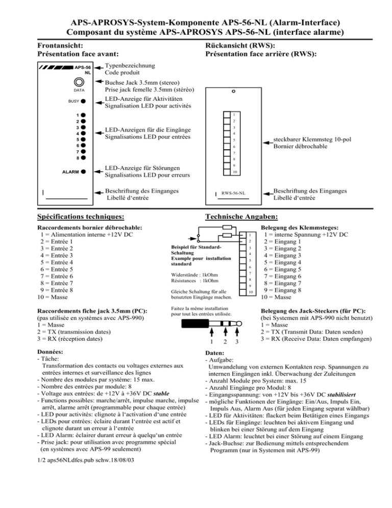
APS-APROSYS-System-Komponente APS-56-NL (Alarm-Interface) Composant du système APS-APROSYS APS-56-NL (interface alarme) Frontansicht: Présentation face avant: Rückansicht (RWS): Présentation face arrière (RWS): APS-56 NL Typenbezeichnung Code produit DATA Buchse Jack 3.5mm (stereo) Prise jack femelle 3.5mm (stéréo) BUSY LED-Anzeige für Aktivitäten Signalisation LED pour activités 1 1 2 3 4 5 6 7 8 2 ALARM 3 LED-Anzeigen für die Eingänge Signalisations LED pour entrées 4 steckbarer Klemmsteg 10-pol Bornier débrochable 5 6 7 8 9 LED-Anzeige für Störungen Signalisations LED pour erreurs 10 Beschriftung des Einganges Libellé d‘entrée Spécifications techniques: Raccordements bornier débrochable: 1 = Alimentation interne +12V DC 2 = Entrée 1 3 = Entrée 2 4 = Entrée 3 5 = Entrée 4 6 = Entrée 5 7 = Entrée 6 8 = Entrée 7 9 = Entrée 8 10 = Masse Raccordements fiche jack 3.5mm (PC): (pas utilisée en systèmes avec APS-990) 1 = Masse 2 = TX (transmission dates) 3 = RX (réception dates) Technische Angaben: 1 2 Beispiel für StandardSchaltung Example pour installation standard 3 4 5 6 7 Widerstände : 1kOhm Résistances : 1kOhm 8 9 Gleiche Schaltung für alle benutzten Eingänge machen. 10 Faitez la même installation pour tout les entrées utilisée. Données: - Tâche: Transformation des contacts ou voltages externes aux entrées internes et surveillance des lignes - Nombre des modules par système: 15 max. - Nombre des entrées par module: 8 - Voltage aux entrées: de +12V à +36V DC stable - Functions possibles: marche/arrêt, impulse marche, impulse arrêt, alarme arrêt (programmable pour chaque entrée) - LED pour activités: clignote à l‘activation d‘une entrée - LEDs pour entrées: éclaire durant l‘entrée est actif et clignote durant un erreur à l‘entrée - LED Alarm: éclairer durant erreur à quelqu‘un entrée - Prise jack: pour utilisation avec programme spécial (en systèmes avec APS-99 seulement) 1/2 aps56NLdfes.pub schw.18/08/03 Beschriftung des Einganges Libellé d‘entrée RWS-56-NL 1 2 3 Belegung des Klemmsteges: 1 = interne Spannung +12V DC 2 = Eingang 1 3 = Eingang 2 4 = Eingang 3 5 = Eingang 4 6 = Eingang 5 7 = Eingang 6 8 = Eingang 7 9 = Eingang 8 10 = Masse Belegung des Jack-Steckers (für PC): (bei Systemen mit APS-990 nicht benutzt) 1 = Masse 2 = TX (Transmit Data: Daten senden) 3 = RX (Receive Data: Daten empfangen) Daten: - Aufgabe: Umwandelung von externen Kontakten resp. Spannungen zu internen Eingängen inkl. Überwachung der Zuleitungen - Anzahl Module pro System: max. 15 - Anzahl Eingänge pro Modul: 8 - Eingangsspannung: von +12V bis +36V DC stabilisiert - mögliche Funktionen der Eingänge: Ein/Aus, Impuls Ein, Impuls Aus, Alarm Aus (für jeden Eingang separat wählbar) - LED für Aktivitäten: flackert beim Betätigen eines Eingangs - LEDs für Eingänge: leuchten bei aktivem Eingang und blinken bei einer Störung auf dem Eingang - LED Alarm: leuchtet bei einer Störung auf einem Eingang - Jack-Buchse: zur Bedienung mittels entsprechendem Programm (nur in Systemen mit APS-99) APS-APROSYS system component APS-56-NL (alarm interface) Componente del sistema APS-APROSYS APS-56-NL (interface alarma) Front view: Vista frontal: Rear view (RWS): Vista posterior (RWS): APS-56 NL Model code Código del producto DATA Jack socket 3.5mm (stereo) Jack hembra estéreo de 3,5 mm BUSY LED display for activities Señalización LED de activación 1 1 2 3 4 5 6 7 8 2 ALARM 3 LED displays for the inputs Señalización LED de entradas 4 pluggable connector block 10 pole Regleta de bornes enchufable 5 6 7 8 9 LED display for errors Señalización LED de errors 10 Input label Rotulación de la entrada Technical specifications: Características técnicas: Distribución de la regleta de bornes: 1 = Alimentación interno +12V DC 2 = Entrada 1 3 = Entrada 2 4 = Entrada 3 5 = Entrada 4 6 = Entrada 5 7 = Entrada 6 8 = Entrada 7 9 = Entrada 8 10 = Masa Distribución del clavija jack 3,5 mm: (no usado en sistemas con APS-990) 1 = Masa 2 = TX (transmitir datos) 3 = RX (recibir datos) Input label Rotulación de la entrada RWS-56-NL 1 2 Example for standard wiring 3 4 5 Ejemplo para cableado standard 6 Resistors : 1kOhm Resistencias : 1kOhmios 9 7 8 10 Make the same wiring for all used inputs Cableado igual para todos 1 Datos: - Tarea: transferencia del contactos o ténsions externos a entradas internos y control de líneas - Número de módulos por sistema: 15 a lo más - Número de entradas por módulo: 8 - Ténsion de entrada: de +12V a +36V DC estable - Funciónes posibles: conexión/desconexión, impulso conexión, impulso desconexión, Alarm desconexión (programmable) - Señalización LED de activación: relucir si actividad una entrada - Señalizacion LED de entradas: lucir durante entrada activo y relucir in suceso de error - Señalizacion LED de errors: lucir durante un error - Jack hembra: para servicio con programa especial (en sistemas con APS-99 solamente) 2 Connection diagram for the connector block: 1 = internal voltage +12V DC 2 = Input 1 3 = Input 2 4 = Input 3 5 = Input 4 6 = Input 5 7 = Input 6 8 = Input 7 9 = Input 8 10 = Ground Connection diagram for the jack plug (PC): (not used at systems with APS-990) 1 = Ground 2 = TX (transmit data) 3 = RX (receive data) 3 Data: - Task: transforming of external contacts respectively voltages to internal inputs inclusive monitoring of the conductors - Number of modules per system: max. 15 - Number of inputs per module: 8 - Input voltage: from +12V to +36V DC stabilized - possible functions of the inputs: On/Off, Impulse On, Impulse Off, Alarm Off (selectable seperately for each input) - LED for aktivities: flickers by operating an input - LEDs for the inputs: illuminated if the input is active and blinking by an error at the input - LED Alarm: illuminated by an error at any input - Jack socket: to operate with the aid of special program (at systems with APS-99 only)
