Regulador de energía en función de la temperatura ambiente
Anuncio
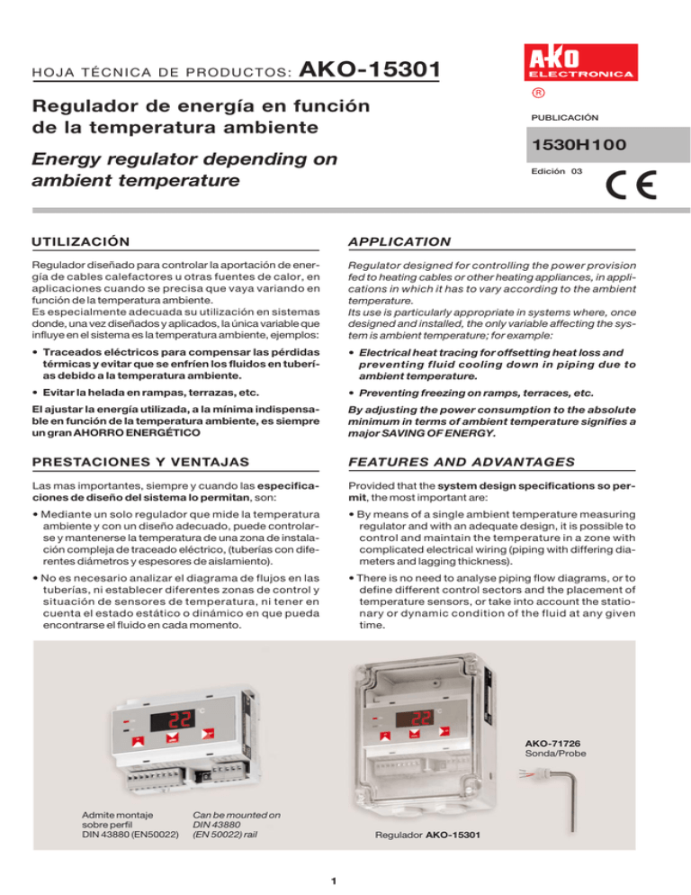
HOJA TÉCNICA DE PRODUCTOS: AKO-15301 R Regulador de energía en función de la temperatura ambiente PUBLICACIÓN 1530H100 Energy regulator depending on ambient temperature Edición 03 UTILIZACIÓN APPLICATION Regulador diseñado para controlar la aportación de energía de cables calefactores u otras fuentes de calor, en aplicaciones cuando se precisa que vaya variando en función de la temperatura ambiente. Es especialmente adecuada su utilización en sistemas donde, una vez diseñados y aplicados, la única variable que influye en el sistema es la temperatura ambiente, ejemplos: Regulator designed for controlling the power provision fed to heating cables or other heating appliances, in applications in which it has to vary according to the ambient temperature. Its use is particularly appropriate in systems where, once designed and installed, the only variable affecting the system is ambient temperature; for example: • Traceados eléctricos para compensar las pérdidas térmicas y evitar que se enfríen los fluidos en tuberías debido a la temperatura ambiente. • Electrical heat tracing for offsetting heat loss and preventing fluid cooling down in piping due to ambient temperature. • Evitar la helada en rampas, terrazas, etc. • Preventing freezing on ramps, terraces, etc. El ajustar la energía utilizada, a la mínima indispensable en función de la temperatura ambiente, es siempre un gran AHORRO ENERGÉTICO By adjusting the power consumption to the absolute minimum in terms of ambient temperature signifies a major SAVING OF ENERGY. PRESTACIONES Y VENTAJAS FEATURES AND ADVANTAGES Las mas importantes, siempre y cuando las especificaciones de diseño del sistema lo permitan, son: Provided that the system design specifications so permit, the most important are: • Mediante un solo regulador que mide la temperatura ambiente y con un diseño adecuado, puede controlarse y mantenerse la temperatura de una zona de instalación compleja de traceado eléctrico, (tuberías con diferentes diámetros y espesores de aislamiento). • By means of a single ambient temperature measuring regulator and with an adequate design, it is possible to control and maintain the temperature in a zone with complicated electrical wiring (piping with differing diameters and lagging thickness). • No es necesario analizar el diagrama de flujos en las tuberías, ni establecer diferentes zonas de control y situación de sensores de temperatura, ni tener en cuenta el estado estático o dinámico en que pueda encontrarse el fluido en cada momento. • There is no need to analyse piping flow diagrams, or to define different control sectors and the placement of temperature sensors, or take into account the stationary or dynamic condition of the fluid at any given time. AKO-71726 Sonda/Probe Admite montaje sobre perfil DIN 43880 (EN50022) Can be mounted on DIN 43880 (EN 50022) rail Regulador AKO-15301 1 • Permiten minimizar el número de zonas de control y ajustar al mínimo la energía aplicada, con la reducción de costes de instalación, mantenimiento y ahorro energético, que ello representa. • They allow the number of control zones to be minimised and the power intake to be reduced to the minimum, with the cost reduction in installation, maintenance and saving in energy, that this signifies. • Permiten ajustar la temperatura del sistema, mediante: - La variación del porcentaje de energía aplicada, respecto a la máxima disponible (programable en parámetro P5). - 3 niveles para corregir las inercias térmicas (programable en parámetro P4). - 3 límites de duración de ciclo (programable en parámetro P7). • They permit system temperature to be set, by: - Varying the percentage of consumed power with respect to the maximum available (programmable with parameter P5). - 3 settings for thermal inertia correction (programmable with parameter P4). - 3 cycle duration limits (programmable with parameter P7). • Permiten visualizar el porcentaje de energía que se está utilizando en cada momento en función de la temperatura ambiente, respecto a la máxima disponible. • Percentage power being employed at any time can be displayed in terms of ambient temperature, with respect to maximum available. • Por programación (parámetro P9) permiten: - El control habitual del sistema en función de la temperatura ambiente. - Tener el sistema siempre conectado para minimizar el tiempo en elevar la temperatura, en las puestas en marcha con fluidos en frío. • Use of parameter P9 to program: - Standard system control regime in terms of ambient temperature. - System always powered up to save temperature-raising time when starting up with fluids in a cold state. • Automatic temperature display to one decimal place from –9.9 ºC to +99.9 ºC and to the nearest degree over the rest of the range. Programmable for working in degrees ºC or ºF. • Visualización automática de la temperatura ambiente en décimas de grado desde –9,9ºC a +99,9ºC y de grados enteros en el resto del rango. Programables para trabajar en grados ºC o ºF • Prepared to work with Pt 100 sensors and can be mounted out of doors or on a DIN rail with the sensor positioned remotely from the regulator. • Están previstos para sondas Pt 100 y pueden instalarse a intemperie o bien sobre perfil DIN con la sonda a gran distancia del regulador. ESPECIFICACIONES TÉCNICAS/TECHNICAL SPECIFICATIONS Ref. de catálogo sin sonda / Catalogue number without probe Alimentación / Power supply AKO-15301 230 V~±10%, 50 Hz Intensidad nominal / Nominal current 13 mA Rango de temperatura / Temperature range -40ºC a +200ºC (-40ºF a +200ºF) Precisión del regulador / Regulator accuracy ± 0.5 ºC Temperatura ambiente de trabajo / Ambient temperature range Temperatura de almacenaje / Storage temperature -25ºC a/to +50ºC -30ºC a/to +75ºC Salida de relé / Relay output SPDT, 10 A, 250 V~, cosw=1 Maniobras del relé / Cycles switch life > 500.000 Bornes para cables / Cable terminals máx. 2,5 mm2 Caja de policarbonato-ABS / Policarbonate-ABS enclosure V0 según UL 94 / V0 to UL 94 Dimensiones exteriores / External sizes 160 x 120 x 66 mm Distancia entre centros fijación / Fixing centres lengths 127,5 x 105 mm Grado de protección / Protection IP 65 Ref. sonda Pt 100 para temp. ambiente / Pt 100 probe for ambient temp. AKO-71726 Ref. m cable prolongación sondas Pt 100 / Extension cable for Pt 100 probes AKO-15586 FUNCIONAMIENTO OPERATION El regulador establece unos ciclos con conexión y desconexión cuyos tiempos van variando en función de la temperatura ambiente que detecta. Asigna tiempos largos de conexión y cortos de desconexión cuando la temperatura ambiente es baja y viceversa cuando es alta. Los varia automáticamente en función de las condiciones climáticas y de los parámetros que previamente se le hayan programado. The regulator establishes on and off cycles the duration of which vary according to the ambient temperature it detects. It allocates long on times and short off times when the ambient temperature is low, and vice versa when it is high. It varies these automatically depending on weather conditions and on the previously programmed parameters. In this way the power provided by the heating cables or heating appliances is regulated in such a manner that it is maximum when the ambient temperature is low, and vice versa. The system is highly indicated for use in making up Con ello se consigue regular la energía que aportan los cables calefactores o fuentes de calor, de tal forma que sea máxima cuando la temperatura ambiente sea baja y 2 heat loss and preventing freezing of fluids carried in piping. viceversa. El sistema es muy adecuado cuando se trata de compensar las pérdidas térmicas para evitar que se enfríen los fluidos en tuberías. Regulator programmable functions: Al regulador se le pueden programar: P1, Visualización en ºC o ºF que se desee. P1, Display of working degrees, ºC o ºF. P2, Temperatura a mantener “Tª mant”. Corresponde a la situación en que si la temperatura ambiente llega a este valor, la aportación de energía debe ser mínima. P2, Temperature to be maintained “Tmaint”. If the ambient temperature reaches this level, the power supplied should be minimum. P3, Temperatura mínima ambiente “Tªmín”. Corresponde a la mínima ambiente previsible que se ha considerado en el diseño, y en la que, de llegarse a este valor, la aportación de energía debe ser máxima. P3, Minimum ambient temperature “Tmin”. This corresponds to the minimum ambient temperature foreseen in design considerations; when this level is reached power supplied should be maximum. 100% 100% % Energía aplicada (P5) % Power (P5) 50% 50% ºC Tª mín. Tª amb. ºC Tª mant. T mín. T amb. T maint. El regulador detecta la temperatura ambiente Tªamb. en cada momento y según sean los valores de temperatura a mantener Tªmant. y la temperatura mínima ambiente Tªmín. programados en P2 y P3 para los cuales se ha realizado el diseño de la instalación, calcula el porcentaje de energía necesaria y establece los tiempos y ciclos adecuados. The regulator is constantly detecting the ambient temperature Tamb. and, depending on the values of the temperature to be maintained Tmaint. and the minimum ambient temperature Tmin. programmed in P2 and P3 for which the installation was designed, it calculates the percentage power necessary and sets the appropriate periods and cycles. P4, Niveles de inercia térmica. En un sistema con distintos diámetros de tuberías, debido a las inercias térmicas de las diferencias de masa entre ellas, podrían darse temperaturas puntuales diferentes a la nominal media que se desea. Para minimizar este efecto, el parámetro P4 permite seleccionar 3 niveles de inercia térmica: 1 = Nivel mínimo, para tuberías de diámetro inferior a 1” 2 = Nivel medio, para tuberías de diámetro entre 1” y 2” 3 = Nivel máximo para tuberías de diámetro superior a 2” P4, Levels of thermal inertia. In a system with different piping diameters, spot temperatures can be encountered different to the desired rated mean due to the thermal inertia resulting from the differences in mass in the various pipe lengths. To minimise this effect, parameter P4 allows the selection of three thermal inertia levels: 1 = Minimum level, for piping with diameter less than 1” 2 = Median level, for piping with diameter between 1” and 2” 3 = Maximum level, for piping with diameter greater than 2” De los distintos diámetros de tubería existentes en un sistema, deberá seleccionarse el nivel que corresponda al menor de ellas, por ser la que tiene una inercia térmica menor y conseguir que las diferencias de temperatura en esta sean mínimas. Téngase en cuenta, que si se escoge un nivel inferior al que corresponda al sistema, se realizarán ciclos mas cortos en mayor cantidad de forma innecesaria. Of the various pipe diameters present in a system, the level selected is that corresponding to the smallest, since this is the one with lowest thermal inertia; in this way the temperature differences in it are minimal. Remember however, that if a level is chosen which is lower than that corresponding to the system, shorter cycles occur at a higher than necessary frequency. P5, Percentage power supplied. The power supplied can be varied from 100% down to 50%, with respect to that which would correspond according to the ambient temperature at the moment. By setting the mean rated temperature of the system to that which it is wished to maintain, the differences are corrected that could arise due to safety factors built into the design. This represents the system commissioning setting. P5, Porcentaje de energía aplicada. Permite variar desde el 100% hasta el 50% la energía aplicada, en relación a la que correspondería en función de la temperatura ambiente del momento. El ajustar la temperatura nominal media del sistema a la que se desea mantener, corrige las diferencias que pudieran darse debido a los factores de seguridad que se tienen en cuenta para los diseños. Ello representa el ajuste de puesta en marcha del sistema. 3 P6, Calibración. Permite ajustar el regulador con la sonda al valor real, si por cualquier motivo hubieran diferencias respecto a la calibración inicial de fábrica. P6, Calibration. Permits adjustment of the regulator to the true value with the sensor, if for whatever reason differences had arisen with respect to the initial factory calibration. P7, Límites de duración de ciclo. Permite limitar la duración del ciclo a tres niveles: 1 = máximo 2 = medio 3 = mínimo El nivel máximo admite ciclos de gran duración, pero es cuando se obtendrán mas diferencias entre las temperaturas puntuales y la nominal media que se desea. Por el contrario, con el nivel mínimo se obtendrán temperaturas puntuales mas ajustadas a la nominal, pero se realizarán ciclos mas cortos en mayor cantidad que a veces puede resultar innecesario. P7, Cycle duration limits. Permits cycle duration to be limited to three levels: 1 = maximum 2 = mean 3 = minimum The maximum level allows long duration cycles, however it is when most differences shall be encountered between spot temperatures and the desired mean rated value. On the other hand, with the minimum level, spot temperatures shall be obtained closer to the rated value, but shorter cycles shall be performed in a greater, possibly unnecessary number. FUNCIONES DEL FRONTAL FRONT PANEL FUNCTIONS LED indicador de relé activado (Intermitente en fase de programación) Relay operational LED indicator (Flashing during programming) Indicador de la temperatura ambiente en la sonda ºC ON Sensor ambient temperature displaying ºF LED indicador de grados °F LED indicator for degrees Fahrenheit, °F UP Tecla para: - Visualizar durante 5” la temperatura a mantener. - Subir valores estando en programación. UP Key for: - Displaying temperature to be maintained for 5 seconds. - Increase values when programming. DOWN Tecla para: - Visualizar durante 5” el % de energía aplicada (P5). - Bajar valores estando en programación. DOWN Key for: - Displaying % power supplied (P5) for 5 seconds. - Decrease values when programming. SET Tecla para: - Visualizar durante 5” el % de energía que está utilizando el sistema. - Aceptar valores estando en programación. - Pulsando mas de 3” se entra en programación. Si se modifica un valor, para que sea aceptado hay que pulsar de nuevo. Transcurridos 30” sin pulsar tecla alguna, se produce una salida automática del estado de programación. SET Key for: - Displaying % power being used by system for 5 seconds. - Accept values when programming. - When depressed more than 3 seconds, programming is accessed. In order to accept an altered value, depress once again. After 30 seconds have elapsed without any key being depressed, automatic exit from the programming status occurs. UP + SET - Pulsando simultáneamente estas teclas durante 3” se vuelve a los parámetros por defecto programados de fábrica (Ver columna DEF en el apartado de descripción de parámetros). UP + SET - By depressing these keys simultaneously for 3 seconds, the factory-programmed, default parameters are restored (See column DEF in the section on parameter description). PROGRAMACIÓN PROGRAMMING Los parámetros sólo deben ser programados o modificados por personal que conozca el funcionamiento y las posibilidades del sistema o equipo donde se aplica. The parameters must only be programmed or altered by staff familiar with the operations and facilities of the system or equipment in which it is applied. Programación de parámetros: Programming parameters: Nivel 1: Pulse la tecla SET durante 3 segundos. El LED “ON” se iluminará de forma intermitente y en el display aparecerá el primer parámetro P1. Pulse la tecla UP (subir valores) para acceder al parámetro siguiente o DOWN (bajar valores) para retroceder al parámetro anterior. Situándonos en el último parámetro EP, pulsando la tecla SET (aceptar valores), el regulador volverá a la situación de indicación de temperatura ambiente y desaparecerá la intermitencia del LED “ON”. Level 1: Press the SET key for 3 seconds. The “ON” LED starts to flash and the first parameter P1 appears on the display panel. Press the UP key (increase values) in order to access the next parameter or DOWN (decrease values) to recover the preceding parameter. When the final parameter EP is reached and the SET key (accept values) is depressed, the regulator returns to the situation of indicating ambient temperature and the “ON” LED ceases flashing. 4 Nivel 2: Para ver el valor actual de cualquier parámetro, sitúese en el que se desea y pulse la tecla SET (aceptar valores). Una vez visualizado, si se quiere modificar pulse las teclas UP (subir) o DOWN (bajar). Pulse la tecla SET (aceptar ) para fijar el nuevo valor. La programación volverá al Nivel 1. INDICACIÓN TEMP. AMBIENTE Level 2: To view the current value of any parameter, proceed to that desired and press the SET (accept values) key. If once displayed, it is wished to alter it, press the UP (increase) or DOWN (decrease) keys. Press the SET (accept) key to fix the new value. The programming shall return to level 1. NIVEL 1 PARAMETROS NIVEL 2 VALORES Variar valor Change value Visualizar valor Display value Valor actual Current value Aceptar nuevo valor Accept new value Nuevo valor New value 3 Seg. Salida Programación Exit programming DESCRIPCIÓN DE LOS PARÁMETROS DESCRIPTION OF PARAMETERS Los valores de la columna DEF, son los que vienen programados de fábrica y a los que se vuelve si se pulsan simultáneamente las teclas UP+SET durante 3 segundos. The values given in the DEF column are those, which come, programmed from factory and which are restored by simultaneously depressing the UP+SET keys for 3 seconds. PARÁMETRO DESCRIPCIÓN P1 Selección de la visualización en °C o en °F RANGO Select display in °C or in °F DEF 0 = °C, 1 = °F 0 5ºC P2 Tªmant. temperatura que se desea mantener Es la temperatura que se desea mantener en la tubería mediante la aplicación de los cables calefactores Tmaint. temperature to be maintained This is the temperature it is desired to keep in the piping through the heating cable application -10ºC a/to+200ºC -10ºF a/to+200ºF P3 Tªmin. temperatura mínima ambiente Corresponde a la temperatura mínima ambiente que se ha previsto, al realizar el diseño para la temperatura que se desea mantener Tmin. minimum ambient temperature Corresponds to the minimum ambient temperature foreseen when designing for the temperature to be maintained -40°C a/to +100°C -40°F a/to +100°F 0°C P4 Nivel de inercia térmica Se ha de tener en cuenta la tubería de Ø mínimo del sistema 1 = Nivel mínimo, para tuberías de diámetro inferior a 1” 2 = Nivel medio, para tuberías de diámetro entre 1” y 2” 3 = Nivel máximo, para tuberías de diámetro superior a 2” Level of thermal inertia Allow for system minimum piping diameter 1 = Minimum level, for piping with diameter less than 1” 2 = Median level, for piping with diameter between 1” and 2” 3 = Maximum level, for piping with diameter greater than 2” 1 a/to 3 2 P5 Porcentaje de energía aplicada Permite reducir la energía facilitada por los cables calefactores Percentage power supplied Permits power fed through the heating cables to be reduced 50% a/to 100% 85% P6 Calibración Permite ajustar el regulador con la sonda al valor real Calibration Permits regulator to be set with the sensor to the true value –20°C a/to +20°C –20°F a/to +20°F 0°C P7 Límite de duración de ciclo Permite limitar la duración del ciclo a tres niveles. 1 = máximo, 2 = medio, 3 = mínimo Cycle duration limit Permit cycle duration to be limited to three levels. 1 = maximum, 2 = mean, 3 = minimum 1 a/to 3 1 P8 Estado del relé en caso de fallo de sonda 0 = La instalación queda desconectada de forma permanente hasta que se repare la sonda 1 = La instalación queda conectada de formapermanente hasta que se repare la sonda Relay status in event of sensor failure 0 = Installation permanently powered down until sensor repaired 1 = Installation kept permanently powered up until sensor repaired 0 = OFF 1 = ON 0 P9 Tipo de control 0 = La instalación está siempre desconectada 1 = La instalación está conectada permanentemente 2 = El regulador controla la energía aportada según la variación de la temperatura ambiente Control mode 0 = Installation is always powered down 1 = Installation is permanently powered up 2 = Regulator controls power supplied according to variation in ambient temperature 0 = OFF 1 = On 2 = CONTROL 2 P10 Número de identificación equipo Equipment identification number 0 a/to 30 0 5 5 6 7 8 9 Puente Jumper Carga / Load 10 11 12 13 14 230 V , Pt 100 Rojo / Red 4 Rojo / Red 3 Detalle conexionado sondas Pt 100 Probe Pt 100 connecting detail Blanco / White 2 Rojo 1 Rojo IP65 protection permits outdoor mounting (optional support AKO-717425). For mounting on 35 mm symmetric DIN 43880 (EN 50022) rail, dismantle the outdoor enclosure containing the regulator, assembly the runner, which is supplied with it, and fasten to the DIN rail. Positioning the sensor: To obtain a correct ambient temperature reading, the sensor must be positioned bearing the following in mind: -That it is exposed to the minimum ambient tempe rature. - Not directly exposed to sunlight. - Exposed to the wind at highest possible air speed. - Ensure no build-up of snow around the sensor. - Prevent damage from mechanical and thermal impact. Wiring: In the event that the sensor and its associated cable are located remotely away from the regulator, installation must NEVER be in a duct together with power, control or mains cables. The electric wiring shall be done according to the following schematic: Blanco Permite su montaje a la intemperie protección IP65 (soporte opcional AKO-717425). Para montaje sobre perfil DIN 43880 (EN 50022) simétrico de 35 mm, desmontar la caja para protección exterior que contiene el regulador, montar la corredera que se suministra con el mismo y fijarlo sobre el perfil DIN. Situación de la sonda: Para que la lectura de la temperatura ambiente sea correcta, la sonda deberá situarse teniendo en cuenta: - Que quede expuesta a la temperatura mínima ambiente. - Que no quede expuesta directamente al sol. - Que quede expuesta al viento de máxima velocidad posible. - Asegurar que la nieve no se acumule alrededor de la sonda. - Prevenirla de daños mecánicos y térmicos Conexionado: La sonda y su cable correspondiente, en caso que se sitúen a distancia del regulador, NUNCA deben instalarse en una conducción junto con cables de potencia, control o alimentación. La conexión eléctrica se realizará de acuerdo con el siguiente esquema: No utilizable INSTALLATION INSTRUCTIONS No utilizable INSTRUCCIONES DE INSTALACIÓN MENSAJES EN EL DISPLAY MESSAGES ON THE DISPLAY PANEL E1 = Sonda averiada (circuito abierto o cruzado). E1 = Sensor fault (open-circuit or shorted) ADVERTENCIAS WARNINGS El uso del equipo no respetando las instrucciones del fabricante, puede alterar los requisitos de seguridad del mismo. Using the unit without respecting the manufacturer’s instructions can alter the safety requirements thereof. AKO Electromecànica, S.A.L. Av. Roquetes, 30-38 08812 S. PERE DE RIBES (Barcelona) Tel. (34) 938 142 700 Fax (34) 938 934 054 Internet: www.ako.es e - m a i l : ako @ ako.es ✉ Apartado (P.O. Box), 5 08800 VILANOVA I LA GELTRÚ (Spain) 351530100 REV. 02 2.001 D.L.: B-7324-01 Nos reservamos el derecho de suministrar materiales que pudieran diferir levemente de los descritos en nuestras publicaciones. 6
