Assembly - Attaching the Light Kit
Anuncio
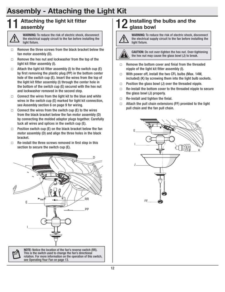
Assembly - Attaching the Light Kit 11 12 Attaching the light kit fitter assembly WARNING: To reduce the risk of electric shock, disconnect the electrical supply circuit to the fan before installing the light fixture. WARNING: To reduce the risk of electric shock, disconnect the electrical supply circuit to the fan before installing the light fixture. □□ Remove the three screws from the black bracket below the □□ □□ □□ □□ □□ □□ Installing the bulbs and the glass bowl CAUTION: Do not over-tighten the hex nut. Over-tightening the hex nut may cause the glass bowl (J) to break. fan motor assembly (D). Remove the hex nut and lockwasher from the top of the light kit fitter assembly (I). Attach the light kit fitter assembly (I) to the switch cup (E) by first removing the plastic plug (PP) in the bottom center hole of the switch cup (E). Insert the wires from the top of the light kit fitter assembly (I) through the center hole in the bottom of the switch cup (E) secured with the hex nut and lockwasher removed in the second step. Connect the wires from the light kit to the blue and white wires in the switch cup (E) marked for light kit connection, see Assembly section 6 on page 9 for wiring. Connect the wires from the switch cup (E) to the wires from the black bracket below the fan motor assembly (D) by connecting the molded adaptor plugs together. Carefully tuck all wires and splices in the switch cup (E). Position switch cup (E) on the black bracket below the fan motor assembly (D) and align the three holes in the black bracket. Re-install the three screws removed in first step in this section to secure the switch cup (E). □□ Remove the bottom cover and finial from the threaded □□ □□ □□ □□ □□ nipple of the light kit fitter assembly (I). With power off, install the two CFL bulbs (Max. 14W, included) (K) by screwing them into the light bulb sockets. Position the glass bowl (J) over the threaded nipple. Re-install the bottom cover to the threaded nipple to secure the glass bowl (J) properly. Re-install and tighten the finial. Attach the pull chain extensions (FF) provided to the light pull chain and the fan pull chain. E I K D J E RR FF PP I NOTE: Notice the location of the fan’s reverse switch (RR). This is the switch used to change the fan’s directional rotation. For more information on the operation of this switch, see Operating Your Fan on page 13. 12 Ensamblaje - Cómo instalar el Kit de Luces 11 12 Cómo instalar el ensamblaje del soporte del kit de luces PRECAUCIÓN: Para disminuir el riesgo de descarga eléctrica, desconecta el circuito de energía del ventilador antes de instalar la lámpara. PRECAUCIÓN:Para disminuir el riesgo de descarga eléctrica, desconecta el circuito de energía del ventilador antes de instalar la lámpara. □□ Quita los tres tornillos del soporte negro debajo del PRECAUCIÓN:No aprietes demasiado la tuerca hexagonal. Apretar demasiado la tuerca hexagonal podría romper el tazón de vidrio (J). ensamblaje del motor del ventilador (D). □□ Retira la tuerca hexagonal y la arandela de seguridad de la parte □□ □□ □□ □□ □□ superior del ensamblaje del soporte del kit de luces (I). Instala el ensamblaje del soporte del kit de luces (I) en la caja del interruptor (E) quitando primero el enchufe de plástico (PP) en el orificio central inferior de la caja del interruptor (E). Inserta los cables desde la parte superior del ensamblaje del soporte del kit de luces (I) a través del orificio central en la parte inferior de la caja del interruptor (E), asegurados con la tuerca hexagonal y la arandela de seguridad que retiraste en el segundo paso. Conecta los cables del kit de luces a los cables azul y blanco en la caja del interruptor (E), marcados para conexión del kit de luces; ver la sección 6 de Ensamblaje en la página 9 para el cableado. Conecta los cables del la caja del interruptor (E) a los cables del soporte negro debajo del ensamblaje del motor del ventilador (D), conectando juntos los enchufes con adaptadores moldeados. Coloca con cuidado todos los cables y empalmes dentro de la caja del interruptor (E). Coloca la caja del interruptor (E) sobre el soporte negro debajo del ensamblaje del motor del ventilador (D) y alinea los tres orificios del soporte negro. Vuelve a instalar los tres tornillos que retiraste en el primer paso en esta sección para asegurar la caja del interruptor (E). □□ Retira la cubierta inferior y el remate de la boquilla roscada □□ □□ □□ □□ □□ del ensamblaje del soporte del kit de luces (I). Con la electricidad apagada, instala las dos bombillas CFL (14 W Máx, incluidas) (K), enroscándolas en los portabombillas. Coloca el tazón de vidrio (J) sobre la boquilla roscada. Reinstala la cubierta inferior en la boquilla roscada para asegurar el tazón de vidrio (J) debidamente. Reinstala el remate y apriétalo. Instala las extensiones de las cadenas para halar (FF) incluidas tanto para la cadena de kit de luces como para la del ventilador. E I K D E Instalar las bombillas y el tazón de vidrio J RR FF PP I NOTA: Marca la posición de los orificios del interruptor de reversa del ventilador (RR). Este es el interruptor utilizado para cambiar la dirección de la rotación del ventilador. Para obtener más información sobre el funcionamiento de este interruptor, consulta Cómo usar el Ventilador en la página 13. 12
