Válvulas de bola Ball valves Class 150-300
Anuncio
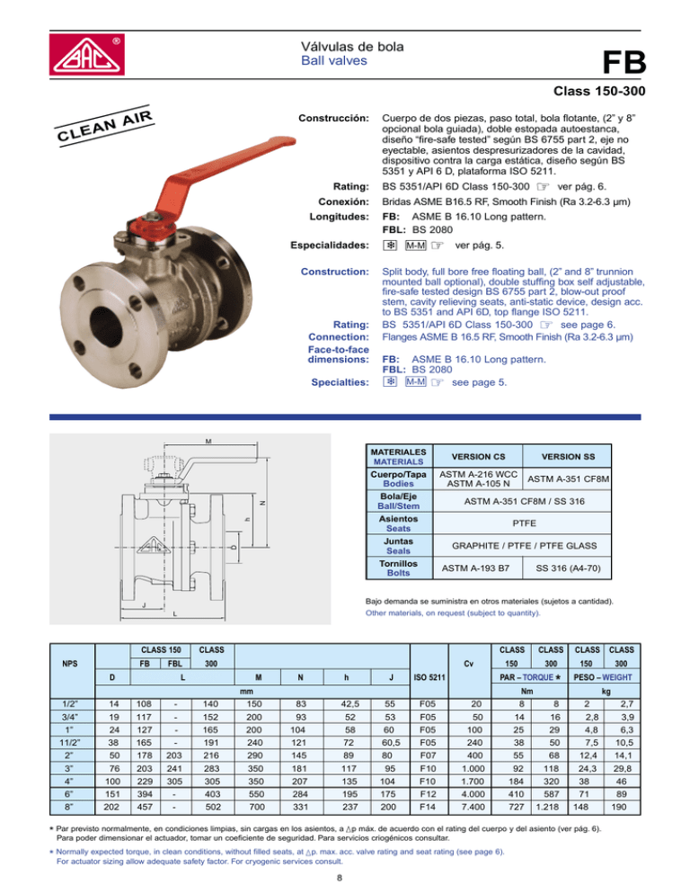
Válvulas de bola Ball valves FB Class 150-300 C N LEA AIR Construcción: Rating: Conexión: Longitudes: Especialidades: Construction: Rating: Connection: Face-to-face dimensions: Specialties: Cuerpo de dos piezas, paso total, bola flotante, (2” y 8” opcional bola guiada), doble estopada autoestanca, diseño “fire-safe tested” según BS 6755 part 2, eje no eyectable, asientos despresurizadores de la cavidad, dispositivo contra la carga estática, diseño según BS 5351 y API 6 D, plataforma ISO 5211. BS 5351/API 6D Class 150-300 ☞ ver pág. 6. Bridas ASME B16.5 RF, Smooth Finish (Ra 3.2-6.3 µm) FB: ASME B 16.10 Long pattern. FBL: BS 2080 ❄ M-M ☞ ver pág. 5. Split body, full bore free floating ball, (2” and 8” trunnion mounted ball optional), double stuffing box self adjustable, fire-safe tested design BS 6755 part 2, blow-out proof stem, cavity relieving seats, anti-static device, design acc. to BS 5351 and API 6D, top flange ISO 5211. BS 5351/API 6D Class 150-300 ☞ see page 6. Flanges ASME B 16.5 RF, Smooth Finish (Ra 3.2-6.3 µm) FB: ASME B 16.10 Long pattern. FBL: BS 2080 ❄ M-M ☞ see page 5. M MATERIALES MATERIALS D h N Cuerpo/Tapa Bodies Bola/Eje Ball/Stem Asientos Seats Juntas Seals Tornillos Bolts R ASTM A-216 WCC ASTM A-105 N ASTM A-351 CF8M ASTM A-351 CF8M / SS 316 PTFE GRAPHITE / PTFE / PTFE GLASS ASTM A-193 B7 SS 316 (A4-70) Other materials, on request (subject to quantity). L CLASS 150 FB VERSION SS Bajo demanda se suministra en otros materiales (sujetos a cantidad). J NPS VERSION CS FBL D CLASS 300 CLASS CLASS 150 300 Cv L M N h J ISO 5211 PAR – TORQUE mm Nm * CLASS CLASS 150 300 PESO – WEIGHT kg 1/2” 14 108 - 140 150 83 42,5 55 F05 20 8 8 2 3/4” 19 117 - 152 200 93 52 53 F05 50 14 16 2,8 3,9 1” 24 127 - 165 200 104 58 60 F05 100 25 29 4,8 6,3 11/2” 38 165 - 191 240 121 72 60,5 F05 240 38 50 7,5 10,5 2” 50 178 203 216 290 145 89 80 F07 400 55 68 12,4 14,1 3” 76 203 241 283 350 181 117 95 F10 1.000 92 118 24,3 29,8 4” 100 229 305 305 350 207 135 104 F10 1.700 184 320 38 46 6” 151 394 - 403 550 284 195 175 F12 4.000 410 587 71 89 8” 202 457 - 502 700 331 237 200 F14 7.400 727 1.218 148 190 * Par previsto normalmente, en condiciones limpias, sin cargas en los asientos, a ▲p máx. de acuerdo con el rating del cuerpo y del asiento (ver pág. 6). Para poder dimensionar el actuador, tomar un coeficiente de seguridad. Para servicios criogénicos consultar. * Normally expected torque, in clean conditions, without filled seats, at ▲p. max. acc. valve rating and seat rating (see page 6). For actuator sizing allow adequate safety factor. For cryogenic services consult. 8 2,7 Válvulas de bola Ball valves FB PN 10-16-25-40 Construcción: CLE Cuerpo de dos piezas, paso total, bola flotante, (DN 50 y DN 200 opcional bola guiada), doble estopada autoestanca, diseño “fire-safe tested” según BS 6755 part 2, eje no eyectable, asientos despresurizadores de la cavidad, dispositivo contra la carga estática, diseño según DIN 3357 y BS 5351, plataforma ISO 5211. DIN 3357 PN10-40 ☞ ver pág. 6. Bridas DIN 2501/1 PN10-40, cara de la brida DIN 2526 forma D (Ra 3.2-6.3 µm) FB: DIN 3202 F18, EN 558-1 serie 14 ≤ DN 100 EN 558-1 serie 15 > DN 100 FBL: DIN 3202 F1, EN 558-1 serie 1 ❄ M-M ☞ ver pág. 5. AIR AN Rating: Conexión: Longitudes: Especialidades: Construction: Split body, full bore free floating ball, (DN 50 and DN 200 trunnion mounted ball optional), double stuffing box self adjustable, fire-safe tested design BS 6755 part 2, blow-out proof stem, cavity relieving seats, anti-static device, design acc. to DIN 3357 and BS 5351, top flange ISO 5211. Rating: DIN 3357 PN10-40 ☞ see page 6. Connection: Flanges DIN 2501/1 PN10-40, facings DIN 2526 form D (Ra 3.2-6.3 µm) Face-to-face dimensions: FB: DIN 3202 F18, EN 558-1 series 14 ≤ DN 100 EN 558-1 serie 15 > DN 100 FBL: DIN 3202 F1, EN 558-1 series 1 Specialties: ❄ M-M ☞ see page 5. MATERIALES MATERIALS M Cuerpo/Tapa Bodies h N Bola/Eje Ball/Stem D Asientos Seats Juntas Seals Tornillos Bolts R J VERSION SS EN 10213-2 1.0619 DIN 17243 C22.8 EN 10213-4 GX5 CrNi 19-10 1.4308 / SS 304 EN10213-2 1.4408 GX5 CrNiMo 19-11-2 EN 10213-4 GX5 CrNiMo 19-11-2 1.4408 / SS 316 PTFE GRAPHITE / PTFE / PTFE GLASS CS 8.8 SS 316 (A4-70) Bajo demanda se suministra en otros materiales (sujetos a cantidad). L Other materials, on request (subject to quantity). PN 16 DN VERSION CS FB D FBL L M N h J ISO 5211 PN 25 PN 40 PN 16 FB Cv PAR-TORQUE mm * PN 25 FBL PN 40 FB FB Nm kg 15 14 115 130 150 83 42,5 55 F05 20 – – 8 – – – 2,8 3,5 20 19 120 150 200 93 52 53 F05 50 – – 15 – – – 3,6 4,2 25 24 125 160 200 104 58 55 F05 100 – – 27 – – – 4,9 5,2 32 30 130 180 240 116 66,5 56 F05 160 – – 39 – – – 7,1 7,6 40 38 140 200 240 121 72 60,5 F05 240 – – 46 – – – 8,3 8,9 50 50 150 230 290 145 89 63 F07 400 – – 64 – – – 12,7 13,4 65 62 170 290 290 161 80 76 180 310 350 181 117 95,5 72 F07 600 77 – 94 16 17,5 – 17 18,2 77 F10 1.000 89 – 108 22 25,5 – 24 27,2 100 100 190 350 350 207 135 86 F10 1.700 171 – 125 120 325 – 550 225 173 140 F12 2.900 217 – 266 31 36,5 – 34 39 320 56 – – 60,5 150 151 350 – 550 284 195 175 F12 4.000 387 – – 475 69 – – 75 200 202 400 – 700 331 237 200 F14 7.400 643 795 – 897 120 – 130 135 – * Par previsto normalmente, en condiciones limpias, sin cargas en los asientos, a ▲p máx. de acuerdo con el rating del cuerpo y del asiento (ver pág. 6). Para poder dimensionar el actuador, tomar un coeficiente de seguridad. Para servicios criogénicos consultar. * FBL PESO - WEIGHT Normally expected torque, in clean conditions, without filled seats, at ▲ p. max. acc. valve rating and seat rating (see page 6). For actuator sizing allow adequate safety factor. For cryogenic services consult. 9
