RC-Empfänger - Champex
Anuncio
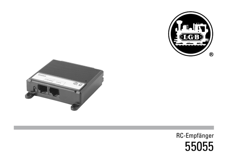
RC-Empfänger 55055 Inhaltsverzeichnis: Seite Reichweite4 MEHRZUGSYSTEM, Einbau 4 Einsatz mehrerer RC-Empfänger für Großanlagen 5 MEHRZUGSYSTEM, Betrieb ANALOGBETRIEB, Einbau 5 ANALOGBETRIEB, Betrieb 6 Bilder 22 Table of Contents: Page Range7 MULTI-TRAIN SYSTEM, Installation 7 Using several Wireless Receivers 8 MULTI-TRAIN SYSTEM, Operation 8 ANALOG OPERATION, Installation 8 ANALOG OPERATION, Operation 9 Figures22 2 Sommaire : Page Portée 10 SYSTÈME MULTITRAIN, Branchement 10 Utilisation de plusieurs récepteurs RC pour les réseaux de grande taille 11 SYSTÈME MULTITRAIN, Fonctionnement 11 RÉSEAU ANALOGIQUE, Branchement 11 RÉSEAU ANALOGIQUE, Fonctionnement 11 Images22 Indice de contenido: Página Alcance16 SISTEMA MULTITREN, Montaje 16 Uso de varios receptores de control remoto para grandes maquetas 17 SISTEMA MULTITREN, Funcionamiento 17 ANALÓGICO, Montaje 17 ANALÓGICO, Funcionamiento 18 Figuras22 Inhoudsopgave:Pagina Reikwijdte13 MEER-TREINENSYSTEEM, Inbouw 13 Gebruik van meerdere RC-ontvangers voor grote banen14 MEER-TREINENSYSTEEM, Bedrijf 14 ANALOOGBEDRIJF, Inbouw 14 ANALOOGBEDRIJF, Bedrijf 15 Illustraties 22 Indice del contenuto : Pagina Ampiezza di copertura 19 SISTEMA CON NUMEROSI TRENI, Installazione 19 Impiego di numerosi ricevitori RC per grandi impianti 20 SISTEMA CON NUMEROSI TRENI, Esercizio 20 ANALOGICO, Installazione 20 ANALOGICO, Esercizio 21 Figures22 3 Mit dem RC-Empfänger und dem RC-Sender 55050 können Sie Ihre Anlage zur Funkfernsteuerung ausbauen. Fahrbefehle werden drahtlos vom Lok-Handy 55016 oder vom Universal-Handy 55015 zur MZS-Zentrale (Mehrzugsystem) oder zum Elektronischen Fahrregler 51070 (Analogbetrieb) übertragen. Bei Großanlagen können Sie mehrere RC-Empfänger einsetzen, so daß sich jede Stelle Ihrer Anlage innerhalb der Reichweite eines RC-Empfängers befindet. Damit können Sie auch die größte Anlage drahtlos fernbedienen. Vorsicht! Dieses Produkt ist nicht wetterfest. Schützen Sie es vor Feuchtigkeit. Achtung! Der RC-Empfänger kann entweder mit dem Mehrzugsystem oder mit einer analog betriebenen Anlage verwendet werden. Schließen Sie den RC-Empfänger nicht gleichzeitig an eine MZS-Zentrale und einen AnalogFahrregler an. Reichweite Die Reichweite der Funkfernsteuerung beträgt ca. 15 bis 20 m (Abb. 4). Sie ist jedoch stark abhängig von örtlichen Gegebenheiten, z. B. anderen Sendern auf gleicher Frequenz (Funkthermometer usw.), Hindernissen zwischen RC-Sender und RC-Empfänger, sowie Funkwellen reflektierende Wände. Stellen Sie bei großen Anlagen den RC-Empfänger in der Mitte der Anlage in Kopfhöhe auf. Die optimale Platzierung lässt sich durch Probieren finden. Vorsicht! Schließen Sie die Westernstecker der LGBBausteine nicht an das Telefon-Netz an. Die LGB-Bausteine würden sofort zerstört. Achtung! Eine absolut sichere Funkübertragung gibt es 4 nicht. Wenn die Reichweite überschritten wird, können keine Fahrbefehle (auch nicht “Nothalt”) mehr gesendet werden. MEHRZUGSYSTEM Einbau Verwenden Sie das beiliegende Kabel mit zwei schmalen viereckigen Westernsteckern. Verbinden Sie die mit “LGBBUS” gekennzeichnete Buchse am RC-Empfänger mit einer entsprechenden Buchse an der MZS-Zentrale (Abb. 2). Stecken Sie die beiliegende Antenne in die Bohrung im Deckel des RC-Empfängers. Stellen Sie den RC-Empfänger so auf, daß die Reichweite von keinem Punkt Ihrer Anlage aus überschritten wird (siehe Reichweite). Hinweise: • Der RC-Empfänger kann von bis zu acht Handys (jeweils mit RC-Sender 55050) Daten empfangen. • Beim Betrieb von vielen Handys können sich jedoch Daten überlagern und verloren gehen. • Universal-Handys im Modus Doppeltraktion zählen als zwei Handys. Einsatz mehrerer RC-Empfänger für Großanlagen (nur mit Mehrzugsystem) Sie können bis zu drei RC-Empfänger einsetzen, um die Reichweite zu erhöhen (Abb. 4). Die RC-Empfänger werden so auf der Anlage platziert, daß sich auch bei Großanlagen jeder Teil der Anlage innerhalb der Reichweite eines RCEmpfängers befindet. Alle RC-Empfänger werden dabei auf dieselbe ID-Nr. 2 programmiert (werkseitige Einstellung). Die Empfänger werden jeweils an eine der mit “LGB-BUS” markierten Buchsen des MZS-Adapters angeschlossen. ID-Nummer Jedes Gerät, das an den LGB-BUS angeschlossen wird, benötigt eine ID-Nummer. Die ID-Nummer des RC-Empfängers ist ab Werk auf ID 2 gestellt und sollte normalerweise nicht geändert werden. • Wenn möglich, sollten keine Nummern doppelt belegt werden. • ID-Nummern 1 und 2 haben höhere Priorität (werden öfters abgearbeitet). • So programmieren Sie die ID-Nr.: 1. Kabel zur MZS-Zentrale herausziehen. 2. Die vier Schrauben auf der Unterseite des Gehäuses herausdrehen. Gehäuse öffnen und DIP-Schalter nach beiliegender Tabelle (Seite 6) auf den gewünschten Code stellen. 3. Gehäuse schließen. 4. Kabel zum normalen Betrieb einstecken. Hinweis: Bei der MZS-Zentrale der ersten Generation funktionieren nur die ID-Nummern 1 und 2. Betrieb Die rote LED am RC-Empfänger leuchtet, wenn dieser betriebsbereit ist. Wenn die Nothalt-Taste eines Handys gedrückt wird, blinkt seine LED. ANALOGBETRIEB Einbau Verwenden Sie das beiliegende Kabel mit zwei breiten viereckigen Westernsteckern. Verbinden Sie die Buchse „51070” am RC-Empfänger mit der Buchse „55055” am Fahrregler 51070 (Abb. 3). Stecken Sie die beiliegende Antenne in die Bohrung im Deckel des RC-Empfängers. Stellen Sie den RC-Empfänger so auf, daß die Reichweite von keinem Punkt Ihrer Anlage aus überschritten wird (siehe Reichweite). Nummer des Stromkreises einstellen Im Analogbetrieb können Sie bis zu acht Fahrregler 51070 mit acht zugehörigen Trafos und acht RC-Empfängern 55055 einsetzen. Damit können Sie bis zu acht getrennte Stromkreise von einem Handy aus bedienen. Sie können aber auch bis zu acht Handys einsetzen, um die einzelnen Stromkreise zu regeln. • Jeder Stromkreis erhält eine Nummer, die am jeweiligen RC-Empfänger 55055 eingestellt wird. Diese Nummer wird als Loknummer im Handy angewählt, um angeschlossenen Fahrregler zu steuern. • So stellen Sie den RC-Empfänger ein: 1. Kabel zum Fahrregler 51070 herausziehen. 2. Die vier Schrauben auf der Unterseite des Gehäuses herausdrehen. Gehäuse öffnen und DIP-Schalter nach beiliegender Tabelle (Seite 6) auf den gewünschten Code 5 stellen. 3. Gehäuse schließen. 4. Kabel zum normalen Betrieb einstecken. Betrieb Die rote LED am RC-Empfänger leuchtet, wenn dieser betriebsbereit ist. Vom Handy aus wählen Sie die Nummer des Stromkreises an (siehe Anleitung des Handys). Dann überträgt der entsprechende RC-Empfänger die Daten vom Handy an den angeschlossenen Fahrregler 51070. Beim Analogbetrieb können nur Geschwindigkeit, Fahrtrichtung und Nothalt gesteuert werden. Achtung! Wählen Sie nicht von zwei Handys aus gleichzeitig denselben Stromkreis an. Die Funkfernsteuerung funktioniert dann nicht richtig. 6 1 0 ON DIP 1 2 3 4 Geräte-ID-Nr. ID 1 2 3 4 5 6 7 1000 0100 1100 0010 1010 0110 1110 Stromkreis-Nr. Nr. 0 1 2 3 4 5 6 7 0001 1001 0101 1101 0011 1011 0111 1111 You can expand your layout to radio remote control with the RC receiver and the 55050 RC sender. Operating commands are transmitted wirelessly from the 55016 locomotive hand controller or from the 55015 universal hand controller to the MTS central unit (Multi Train System) or to the 51070 electronic locomotive controller (analog operation). You can use several RC receivers on large layouts so that each part of your layout is within range of an RC receiver. This will allow you to operate even the largest layout wirelessly by remote control. Caution! This product is not weatherproof. Protect it from moisture. Important! The RC receiver can be used either with the multi train system or with a layout operated with analog. Do not connect RC receiver to an MTS central unit at the same time as an analog locomotive controller. Range The range of the radio remote control is about 15 to 20 meters / 16 to 21 feet (Fig. 4). However, it depends a great deal on other factors in the area, such as other senders on the same frequency (radio controlled thermometers, etc.), obstacles between the RC sender and the RC receiver, as well as walls reflecting radio waves. On large layouts, locate the RC receiver in the center of the layout at head height. You will have to experiment to find the best location. Caution! Do not connect the Western Electric plugs on the LGB components to the telephone system. This would destroy the LGB components immediately. Important! There is no such thing as absolutely reliable radio transmission. No operation commands (not even “Emergency Stop“) can be sent if the range is exceeded. MULTI TRAIN SYSTEM Installation Use the cable with two narrow rectangular Western Electric plugs that comes with the receiver. Connect the socket marked “LGB-BUS“ on the RC receiver with a corresponding socket on the MTS central unit (Fig. 2). Plug the antenna included with the receiver into the hole in the cover for the RC receiver. Locate the RC receiver so that the range is not exceeded at any point on your layout (see Range). Notes: • The RC receiver can receive data from up to eight hand controllers (each one with the 55050 RC sender). • However, when you are operating many hand controllers, data can become superimposed on each other and become lost. • Universal hand controllers in the multiple unit mode count as two hand controllers. 7 Using Several RC Receivers for Large Layouts (only with the Multi Train System) You can use up to three RC receivers in order to increase the range (Fig. 4). The RC receivers are located on the layout such that even on large layouts every part of the layout is within range of an RC receiver. All of the RC receivers in such an installation are programmed to the same ID No. 2 (setting as delivered from the factory). The receivers are each connected to one of the sockets marked “LGB-BUS“ on the MTS adapter. ID Number Each device that is connected to the LGB BUS has to have an ID number. The ID number for the RC receiver comes from the factory set for ID 2 and normally should not be changed. • If possible, no number should be used at the same time for two different devices. • ID Numbers 1 and 2 have higher priority (are processed more often). • This is how you program the ID number: 1. Disconnect the cable to the MTS central unit. 2. Unscrew the four screws on the underside of the housing. Open the housing and set the DIP switches to the desired code using the table included with the unit (Page 9). 3. Replace the housing. 4. Plug the cable in for normal operation. Note: Only ID Numbers 1 and 2 work on the first generation MTS central units. 8 Operation The red LED on the RC receiver lights up when the receiver is ready for operation. If the emergency stop button for a hand controller is pressed, its LED will blink. ANALOG OPERATION Installation Use the cable with two wide rectangular Western Electric plugs that comes with the receiver. Connect the socket marked “51070“ on the RC receiver with the socket marked “55055“ on the 51070 locomotive controller (Fig. 3). Plug the antenna included with the receiver into the hole in the cover for the RC receiver. Locate the RC receiver so that the range is not exceeded at any point on your layout (see Range). Setting the Numbers for Track Power Circuits In analog operation you can use up to eight 51070 locomotive controllers with eight transformers assigned to them and eight 55055 RC receivers. This means you can operate up to eight separate track power circuits from one hand controller. You can also use up to eight hand controllers to operate the individual track power circuits. • Each track power circuit is given a number that is set on the 55055 RC receiver assigned to it. This number is selected as a locomotive number in the hand controller in order to control the locomotive controller connected to it. • This is how you set the RC receiver: 1. Unplug the cable from the 51070 locomotive controller. 2. Unscrew the four screws on the underside of the housing. Open the housing and set the DIP switches to the desired code using the table included with the unit (Page 9). 3. Replace the housing. 4. Plug the cable in for normal operation. Operation The red LED on the RC receiver lights up when the receiver is ready for operation. Using the hand controller, select the number for the track power circuit (see instructions for the hand controller). The RC receiver assigned to that track power circuit will transmit the data from the hand controller to the 51070 locomotive controller connected to it. In analog operation only speed, direction, and emergency stop can be controlled. Important! Do not select the same track power circuit at the same time from two hand controllers. The radio remote control will not work correctly. 1 0 Device ID No. ID 1 2 3 4 5 6 7 ON DIP 1 2 3 4 1000 0100 1100 0010 1010 0110 1110 Power Circuit No. 0 1 2 3 4 5 6 7 0001 1001 0101 1101 0011 1011 0111 1111 9 Le récepteur RC et l’émetteur RC 55050 vous permettent d’équiper votre réseau pour la radiotélécommande. Les ordres de conduite sont transmis sans fil à partir de la télécommande 55016 ou de la télécommande universelle 55015 à la centrale MZS (système multitrain) ou au régulateur de marche électronique 51070 (mode analogique). Pour les grands réseaux, vous pouvez utiliser plusieurs récepteurs RC, de manière à ce que chaque point de votre réseau se trouve dans le rayon de portée de l’un des récepteurs RC. Le système de télécommande sans fil est donc envisageable même pour le plus grand des réseaux. Attention ! Ce produit ne résiste pas aux intempéries. Protégez-le de l’humidité. Attention ! Le récepteur RC peut être utilisé soit avec un système multitrain, soit avec un réseau exploité en mode analogique. Ne raccordez pas votre récepteur RC simultanément à une centrale MZS et à un régulateur de marche analogique. Portée Le rayon de portée de la radiotélécommande est d’environ 15 à 20 mètres (Img. 4). Il dépend toutefois beaucoup des conditions sur l‘emplacement du réseau, à savoir l‘existence éventuelle d‘autres émetteurs sur la même fréquence (thermomètres etc.), l’existence d’obstacles entre l’émetteur RC et le récepteur RC ainsi que l’existence de parois réfléchissant les ondes radio. Pour un réseau de taille importante, placez le récepteur RC au milieu du réseau, à hauteur de tête. Seuls plusieurs essais vous permettront de trouver l’emplacement idéal. Prudence ! Ne raccordez pas les connecteurs western des 10 modules LGB au réseau téléphonique. Ce branchement leur serait fatal. Attention ! Il n’existe pas de transmission radio absolument fiable. A partir du moment où le rayon de portée est dépassé, aucun ordre de conduite («arrêt d’urgence» y compris) ne peut plus être transmis. SYSTEME MULTITRAIN Branchement Utilisez le câble fourni avec deux petits connecteurs western rectangulaires. Reliez la prise marquée «LGB-BUS» du le récepteur RC à l‘une des prises correspondantes de la centrale MZS (Img. 2). Enfichez l’antenne fournie dans le couvercle du récepteur RC (trou prévu à cet effet). Placez le récepteur RC de manière à ce que le rayon de portée ne soit dépassé en aucun point du réseau (voir rayon de portée). Remarque : • Le récepteur RC peut recevoir des données provenant de jusqu’à huit télécommandes (équipées chacune d’un émetteur RC 55050). • Lors de l‘exploitation de nombreuses télécommandes, les données peuvent toutefois interférer et se perdre. • Les télécommandes universelles en mode double-traction comptent pour deux télécommandes. Utilisation de plusieurs récepteurs RC pour les réseaux de grande taille (uniquement avec système multitrain) Vous pouvez utiliser jusqu’à trois récepteurs RC afin d’augmenter le rayon de portée (Img. 4). Les récepteurs RC sont placés sur le réseau de manière à ce que chaque partie du réseau se trouve dans le rayon de portée d’un récepteur RC, même sur les réseaux de grande taille. Tous les récepteurs RC sont alors programmés sur le même numéro ID 2 (paramètre d‘usine). Les récepteurs sont respectivement raccordés à l’une des prises marquées «LGB-BUS» de l’adaptateur MZS. Numéro ID Chaque appareil relié au BUS LGB a besoin d’un numéro d’identification. Le numéro ID du récepteur RC défini au départ d’usine est 2 et normalement, il ne doit pas être modifié. • Dans la mesure du possible, un même numéro ne doit pas être attribué deux fois. • Les numéros ID 1 et 2 ont une priorité supérieure (seront traités plus souvent) • Pour programmer le numéro ID, procédez de la manière suivante: 1. Débrancher le câble de la centrale MZS. 2. Défaire les quatre vis sur la partie inférieure du boîtier. Ouvrir le boîtier et, selon le tableau fourni (page 12), positionner le commutateur DIP sur le code souhaité. 3. Fermer le boîtier. 4. Enficher le câble pour l’exploitation normale. Remarque : Sur les centrales MZS de la première génération, seuls les numéros ID 1 et 2 fonctionnent. Exploitation Exploitatoion La LED rouge du récepteur RC s’allume dès que celui est opérationnel. Lorsque la touche d’arrêt d’urgence d’une télécommande est enfoncée, sa LED s’allume. EXPLOITATION ANALOGIQUE Branchement Utilisez le câble fourni avec deux gros connecteurs western rectangulaires. Reliez la prise «51070» du récepteur RC à la prise «55055» du régulateur de marche 51070 (Img. 3). Enfichez l’antenne fournie dans le couvercle du récepteur RC (trou prévu à cet effet). Placez le récepteur RC de manière à ce que le rayon de portée ne soit dépassé en aucun point du réseau (voir rayon de portée). Définir le numéro du circuit électrique En mode d’exploitation analogique, vous pouvez utiliser jusqu’à huit régulateurs de marche 51070 avec huit transformateurs correspondants et huit récepteurs RC 55055. Vous pouvez ainsi commander jusqu’à huit circuits électriques distincts à partir d’une seule télécommande. Mais vous pouvez également utiliser jusqu’à huit télécommandes afin de réguler les différents circuits électriques. • Chaque circuit électrique se voit attribuer un numéro paramétré sur le récepteur RC 55055 correspondant. Ce numéro est sélectionné sur la télécommande comme numéro de loco afin de commander le régulateur de marche raccordé. • Pour paramétrer le récepteur RC, procédez de la manière suivante : 1. Débrancher le câble reliant le régulateur de marche 11 51070. 2. Défaire les quatre vis sur la partie inférieure du boîtier. Ouvrir le boîtier et, selon le tableau fourni (page 12), positionner le commutateur DIP sur le code souhaité. 3. Fermer le boîtier. 4. Enficher le câble pour l’exploitation normale. Exploitation La LED rouge du récepteur RC s’allume dès que celui est opérationnel. A partir de la télécommande, sélectionnez le numéro du circuit électrique (voir notice de la télécommande). Le récepteur RC correspondant transmet alors les données de la télécommande au régulateur de marche 51070 raccordé. En mode d’exploitation analogique, seuls la vitesse, le sens de marche et l’arrêt d’urgence peuvent être commandés. Attention ! Ne sélectionnez pas le même circuit électrique simultanément à partir de deux télécommandes. La radiotélécommande ne fonctionnera pas correctement. 12 1 0 ON DIP 1 2 3 4 Numéro d’identification des appareils ID 1 1000 2 0100 3 1100 4 0010 5 1010 6 0110 7 1110 Numéro de circuit Nr. 0 1 2 3 4 5 6 7 0001 1001 0101 1101 0011 1011 0111 1111 Met de RC-ontvanger en de RC-zender 55050 kunt u uw modelbaan uitbreiden met een radiografische afstandsbediening. De rijopdrachten worden draadloos van de Loc-Handy 55016 of van de Universal-Handy 55015 naar de MZS-centrale (meer-treinensysteem) of naar de elektronische rijregelaar 51070 (analoogbedrijf) overgedragen. Bij grote modelbanen kunt u meerdere RC-ontvangers gebruiken zodat u zich op elke plek van uw modelbaan binnen de reikwijdte van de RC-ontvanger bevindt. Zodoende kunt u ook grote banen radiografisch op afstand bedienen. Voorzichtig! Dit product is niet waterdicht, bescherm het tegen vocht. Voorzichtig! De RC-ontvanger kan of met een meer-treinensysteem of voor een analoog bestuurde modelbaan gebruikt worden. Sluit de RC-ontvanger niet gelijktijdig op een MZScentrale en een analoge rijregelaar aan. Reikwijdte De reikwijdte van de radiografische besturing bedraagt ca. 15 tot 20 meter (Afb. 4). Het is echter sterk afhankelijk van plaatselijke omstandigheden zoals, bijv. andere zenders op dezelfde frequentie (radiografische thermometer e.d.), hindernissen tussen zender en ontvanger, alsmede wanden die radiogolven reflecteren. Plaats de ontvanger bij grotere modelbanen in het midden van de baan op ooghoogte. De optimale plaats kunt u proefondervindelijk vaststellen. Voorzichtig! Sluit de zgn. Westernstekker van de LGBmodules niet op het telefoonnet aan want de LGB-modules zijn dan direct defect. Voorzichtig! Een absoluut betrouwbare radioverbinding bestaat niet. Als de reikwijdte overschreden wordt, kunnen geen rijdopdrachten (ook de Anoodstop) meer verzonden worden. MEER-TREINENSYSTEEM Inbouw Gebruik de meegeleverde kabel met de twee smalle vierkante westernstekkers (4/6). Verbind die met de LGB-BUS stekkerbus van de RC-ontvanger aan de overeenkomstig gemerkte stekkerbus aan de MZS-centrale (Afb. 2). Steek de meegeleverde antenne in de boring in het deksel van de RContvanger. Stel de ontvanger zo op dat de reikwijdte vanaf geen enkele plek op uw modelbaan overschreden wordt. (zie reikwijdte). Opmerking: • De RC-ontvanger kan van max. 8 Handy’s (elk uitgerust met RC-zender) de gegevens verwerken. • Bij het gebruik van meerdere Handy’s kunnen echter de gegevens elkaar verstoren of verloren gaan. • Universele Handy’s in de modus dubbeltractie tellen als twee Handy’s. 13 Gebruik van meerdere RC-ontvangers voor grote banen (alleen met meer-treinensysteem) U kunt maximaal 3 RC-ontvangers toepassen om de reikwijdte te vergroten (Afb. 4). De RC-ontvangers worden zodanig geplaatst dat ook bij grotere banen elk deel van de baan zich binnen de reikwijdte van de RC-ontvanger bevindt. Alle RC-ontvangers worden daarbij op hetzelfde ID-nr. 2 geprogrammeerd (fabrieksinstelling). De ontvangers worden elk aan een met “LGB-BUS” gemarkeerde stekkerbus van de MZS-adapter aangesloten. ID-nummer Elk apparaat dat aan de LGB-BUS wordt aangesloten heeft een ID-nummer nodig. Het ID-nummer van de RC-ontvanger is fabrieksmatig op 2 ingesteld en hoeft normaliter niet gewijzigd te worden. • Indien mogelijk geen nummers dubbel beleggen. • De ID-nummers 1 en 2 hebben een hogere prioriteit (worden vaker verwerkt). • Zo programmeert u het ID-nr: 1. Kabel naar de MZS-centrale er uit trekken. 2. De 4 schroeven aan de onderzijde van de behuizing losdraaien. Behuizing openen en de dipschakelaar volgens bijgevoegde tabel (pag. 15) op de gewenste code instellen. 3. behuizing weer sluiten en schroeven vast draaien. 4. kabel voor het standaardbedrijf er weer insteken. Opmerking: Bij de MZS-centrale van de eerste generatie werken alleen de ID-nummers 1 en 2. 14 Bedrijf De rode LED op de RC-ontvanger licht op als deze bedrijfsgereed is. Als de noodstop toets op een Handy ingedrukt wordt, knippert zijn LED. ANALOOGBEDRIJF Inbouw Gebruik de meegeleverde kabel met de twee brede rechthoekige westernstekkers (8/8). Verbind de bus “51070“ van de RC-ontvanger met de bus “55055“ van de rijregelaar 51070 (afb. 3). Steek de meegeleverde antenne in de boring in het deksel van de RC-ontvanger. Stel de ontvanger zo op dat de reikwijdte vanaf geen enkele plek op uw modelbaan overschreden wordt. (zie reikwijdte) Nummer van de stroomkring instellen In het analoge bedrijf kunt u max. 8 rijregelaars 51070 met 8 daarbij behorende trafo‘s en 8 RC-ontvangers 55055 gebruiken. Hiermee kunt u max. 8 gescheiden stroomkringen vanaf 1 Handy bedienen. U kunt echter ook max. 8 Handy‘s gebruiken om de afzonderlijke stroomkringen apart te bedienen. • Elke stroomkring krijgt een nummer welke op de desbetreffende RC-ontvanger 55055 ingesteld wordt. Dit nummer wordt in de Handy als locnummer aangekozen om de aangesloten rijregelaar aan te kunnen sturen. • Zo programmeert u het ID-nr: 1. Kabel naar de MZS-centrale er uit trekken. 2. De 4 schroeven aan de onderzijde van de behuizing losdraaien. Behuizing openen en de dipschakelaar volgens bijgevoegde tabel (pag. 15) op de gewenste code instellen. 3. behuizing weer sluiten en schroeven vast draaien. 4. kabel voor het standaardbedrijf er weer insteken. Bedrijf De rode LED op de RC-ontvanger licht op als deze bedrijfsgereed is. Op de Handy kiest u het nummer van de stroomkring (zie de gebruiksaanwijzing van de Handy). Dan draagt de desbetreffende RC-ontvanger de gegevens van de Handy over aan de aangesloten rijregelaar. Bij het analoge bedrijf kunnen alleen snelheid, rijrichting en noodstop aangestuurd worden. Let op! Kies niet gelijktijdig vanaf twee Handy‘s dezelfde stroomkring. De afstandbediening werkt dan niet goed. 1 0 ON DIP 1 2 3 4 Apparaat ID-nr. ID 1 2 3 4 5 6 7 1000 0100 1100 0010 1010 0110 1110 Stroomkring nr. Nr. 0 1 2 3 4 5 6 7 0001 1001 0101 1101 0011 1011 0111 1111 15 Con el receptor y el transmisor para control remoto (RC) 55050 puede ampliar su maqueta de trenes para control remoto por radio. Las órdenes de marcha se transmiten vía inalámbrica desde el móvil de locomotora 55016 o desde el móvil universal 55015 a la central MZS (sistema multitren) o al regulador electrónico de marcha 51070 (funcionamiento en modo analógico). En maquetas de trenes de grandes proporciones puede utilizar varios receptores de control remoto de tal modo que cada punto de la maqueta se encuentre dentro del alcance de un receptor de control remoto. De este modo puede mandar a distancia por vía inalámbrica incluso la maqueta de trenes más grande. ¡Precaución! Este producto no es resistente a las inclemencias meteorológicas. Protéjalo de la humedad. ¡Atención! El receptor de control remoto puede utilizarse bien con el sistema multitren o con una maqueta de funcionamiento analógico. No conecte simultáneamente el receptor de control remoto a una central MZS y a un regulador de marcha analógico. haciendo un par de pruebas. ¡Precaución! No conecte el conector Western de los módulos LGB a la red telefónica. De lo contrario, los módulos LGB resultarían destruidos de manera inmediata. ¡Atención! No existe una transmisión por radio absolutamente segura. Si se rebasa el alcance, ya no se pueden enviar órdenes de marcha (ni siquiera “Parada de emergencia“). Alcance El alcance del control remoto por radio es de aprox. 15 hasta 20 m (Fig. 4). Sin embargo, depende en gran medida de las circunstancias locales, p. ej., de la presencia de otros transmisores en la misma frecuencia (termómetro por radio, etc.), obstáculos entre el transmisor y el receptor de control remoto así como paredes que reflejen las ondas de radio. En maquetas de trenes de grandes proporciones, instale el receptor de control remoto en el centro de la maqueta a la altura de la cabeza. La ubicación óptima se determina Notas: • El receptor de control remoto puede recibir datos de hasta ocho móviles (con sus respectivos transmisores RC 55050). • Sin embargo, si se utilizan muchos móviles, pueden solaparse y perderse los datos. • Los móviles universales en el modo doble tracción cuentan como dos móviles. 16 SISTEMA MULTITREN Montaje Utilice el cable con dos conectores Western rectangulares estrechos que se adjunta. Conecte la hembrilla con la identificación “LGB-BUS“ del receptor de control remoto a la hembrilla correspondiente de la central MZS (Fig. 2). Enchufe la antena adjunta en el agujero taladrado en la tapa del receptor de control remoto. Coloque el receptor de control remoto de tal modo que no se rebase el alcance desde ningún punto de la maqueta de trenes (véase Alcance). Uso de varios receptores de control remoto para grandes maquetas (sólo con sistema multitren) Es posible montar hasta tres receptores de control remoto para aumentar el alcance (Fig. 4). Los receptores de control remoto se colocan en la maqueta de modo que incluso en maquetas de grandes proporciones cualquier punto de la maqueta se encuentre dentro del alcance del receptor RC. Todos los receptores RC se programan al mismo número ID 2 (preconfiguración de fábrica). Los receptores se conectan a una de las hembrillas con la identificación “LGB-BUS“ del adaptador MZS. Número ID Cada dispositivo que se conecta al BUS LGB necesita un número ID. El número ID del receptor de control remoto viene configurado de fábrica a ID 2 y, en condiciones normales, no debería modificarse. • Si es posible, no debe asignarse ningún número ID dos veces. • Los números ID 1 y 2 tienen prioridad más alta (se procesan con mayor frecuencia). • La programación del número ID se realiza de la siguiente manera: 1. Extraer el cable que va a la central MZS. 2. Desatornillar los cuatro tornillos situados en el lado inferior de la carcasa. Abrir la carcasa y colocar el microinterruptor DIP en el código deseado conforme a la tabla adjunta (página 18). 3. Cerrar la carcasa. 4. Enchufar el cable para el funcionamiento normal. Nota: En la central MZS de primera generación funcionan únicamente los números ID 1 y 2. Funcionamiento El LED rojo del receptor de control remoto se enciende cuando éste está operativo. Al pulsar la tecla de parada de emergencia de un móvil destella el LED de la misma. FUNCIONAMIENTO EN MODO ANALÓGICO Montaje Utilice el cable que se adjunta con dos conectores Western rectangulares anchos. Conecte la hembrilla “51070“ del receptor de control remoto a la hembrilla “55055“ del regulador de marcha 51070 (Fig. 3). Enchufe la antena que se adjunta en el agujero taladrado en la tapa del receptor RC. Coloque el receptor RC de tal modo que ningún punto de la maqueta de trenes quede a una distancia del receptor superior al alcance (véase Alcance). Configuración del número de circuito En el funcionamiento en modo analógico es posible utilizar hasta ocho reguladores de marcha 51070 con sus ocho transformadores asociados y ocho receptores de control remoto 55055. De este modo se pueden manejar hasta ocho circuitos separados desde un mismo móvil. También puede utilizar hasta ocho móviles distintos para regular los distintos circuitos. • Cada circuito tiene asignado un número que se configura en el receptor de control remotor 55055 en cuestión. Este número se marca en el móvil como número de locomotora para controlar el regulador de marcha conectado. • La configuración del receptor de control remoto se realiza de la siguiente manera: 17 1. Extraer el cable que va al regulador de marcha 51070. 2. Desatornillar los cuatro tornillos situados en el lado inferior de la carcasa. Abrir la carcasa y colocar el microinterruptor DIP en el código deseado conforme a la tabla adjunta (página 18). 3. Cerrar la carcasa. 4. Enchufar el cable para el funcionamiento normal. Funcionamiento El LED rojo del receptor de control remoto se ilumina cuando éste está operativo. Marque con el móvil el número del circuito (véanse instrucciones del móvil). Acto seguido, el receptor de control remoto correspondiente transmite los datos del móvil al regulador de marcha conectado 51070. En el funcionamiento en modo analógico es posible controlar únicamente la velocidad, el sentido de la marcha y la parada de emergencia. ¡Atención! No marque simultáneamente desde dos móviles el mismo circuito. En tal caso, el control remoto por radio no funciona correctamente. 18 1 0 ON DIP 1 2 3 4 Nº ID de dispositivo ID 1 2 3 4 5 6 7 1000 0100 1100 0010 1010 0110 1110 Nº de circuito Nr. 0 1 2 3 4 5 6 7 0001 1001 0101 1101 0011 1011 0111 1111 Con il ricevitore RC (Radio-Comando) ed il trasmettitore RC 55050 Voi potete trasformare il Vostro impianto per il comando a distanza via radio. I comandi di marcia vengono trasmessi senza fili dal portatile per locomotive 55016 oppure dal portatile universale 55015 alla Centrale MZS (sistema per molti treni) oppure al regolatore di marcia elettronico 51070 (funzionamento analogico). In caso di grandi impianti Voi potete impiegare numerosi ricevitori RC, cosicché ciascun punto del Vostro impianto si trovi all’interno dell’ampiezza di copertura di un ricevitore RC. In tal modo Voi potete comandare a distanza senza fili anche il più grande impianto. Attenzione! Questo prodotto non è resistente alle intemperie. Vogliate proteggerlo dall’umidità. Attenzione! Il ricevitore RC può venire impiegato sia con il sistema per numerosi treni, sia con un impianto esercito in modo analogico. Non collegate il ricevitore RC contemporaneamente ad una Centrale MZS e ad un regolatore di marcia analogico. Ampiezza di copertura L’ampiezza di copertura del comando a distanza via radio ammonta circa da 15 sino a 20 m (Fig. 4). Essa è tuttavia fortemente dipendente dalle circostanze locali, ad es. altri trasmettitori sulla stessa frequenza (termometri via radio ecc.), impedimenti tra trasmettitore RC e ricevitore RC, nonché pareti riflettenti per le onde radio. In caso di grandi impianti, vogliate collocare il ricevitore RC nel centro dell’impianto all’altezza della testa. La collocazione ottimale si può trovare mediante sperimentazione. Attenzione! Non collegate le spine a innesto Western dei componenti LGB alla rete telefonica. Tali moduli costruttivi LGB verrebbero immediatamente danneggiati. Attenzione! Una trasmissione via radio assolutamente sicura non è ottenibile. Quando l’ampiezza di copertura viene oltrepassata, non può più venire inviato alcun comando di marcia (nemmeno “arresto di emergenza”). SISTEMA CON NUMEROSI TRENI Installazione Vogliate utilizzare l’accluso cavetto con due piccole spine a innesto quadrangolari Western. Collegate la boccola contrassegnata con “LGB-BUS” sul ricevitore RC con una corrispondente boccola sulla Centrale MZS (Fig. 2). Innestate l’acclusa antenna nella foratura nel coperchio del ricevitore RC. Vogliate collocare il ricevitore RC cosicché non venga oltrepassata l’ampiezza di copertura di alcun punto del Vostro impianto (si veda Ampiezza di copertura). Avvertenze: • Il ricevitore RC può ricevere dati sino al massimo da otto portatili (ciascuno con trasmettitore RC 55050). • In caso di esercizio con numerosi portatili tuttavia i dati possono sovrapporsi ed andare persi. • I portatili universali nella modalità doppia trazione contano come due portatili. 19 Impiego di numerosi ricevitori RC per grandi impianti (solo con sistema per numerosi treni) Voi potete impiegare sino a tre ricevitori RC, per accrescere l’ampiezza di copertura (Fig. 4). Tali ricevitori RC vengono collocati sull’impianto cosicché anche in caso di grandi impianti ciascuna parte dell’impianto si trovi all’interno dell’ampiezza di copertura di un dato ricevitore RC. In tal caso tutti i ricevitori RC vengono programmati sullo stesso numero di ID 2 (impostazione di fabbrica). I ricevitori vengono rispettivamente collegati ad una della boccole contrassegnate con “LGB-BUS” dell’adattatore MZS. Numero ID Ciascun apparato che viene collegato al BUS LGB ha bisogno di un numero di ID. Tale numero ID del ricevitore RC è impostato di fabbrica sul ID 2 e normalmente non dovrebbe venire modificato. • Qualora possibile, non dovrebbe venire assegnato nessun numero doppio. • I numeri ID 1 e 2 hanno una priorità più elevata (vengono elaborati più spesso). • Vogliate così programmare i numeri ID: 1. Estraete il cavetto verso la Centrale MZS. 2. Svitate in fuori le quattro viti sulla faccia inferiore dell’involucro. Aprite l’involucro ed impostate il commutatore DIP sul codice desiderato secondo l’acclusa tabella (Pagina 21). 3. Chiudete l’involucro. 4. Innestate il cavetto per il normale funzionamento. Avvertenza: Nel caso delle Centrali MZS della prima genera- 20 zione funzionano soltanto i numeri ID 1 e 2. Esercizio Il LED rosso sul ricevitore RC si illumina, quando questo è pronto al funzionamento. Quando viene premuto il tasto Arresto di emergenza di un portatile, il suo LED lampeggia. FUNZIONAMENTO ANALOGICO Installazione Vogliate utilizzare l’accluso cavetto con due larghe spine rettangolari a innesto Western. Collegate la boccola “51070” sul ricevitore RC con la boccola “55055” sul regolatore di marcia 51070 (Fig. 3). Innestate l’acclusa antenna nella foratura nel coperchio del ricevitore RC. Vogliate collocare il ricevitore RC cosicché non venga oltrepassata l’ampiezza di copertura di alcun punto del Vostro impianto (si veda Ampiezza di copertura). Impostazione del numero dei circuiti di corrente Nel funzionamento analogico Voi potete impiegare sino ad otto regolatori di marcia 51070 con otto corrispondenti trasformatori ed otto ricevitori RC 55055. In questo modo da un solo portatile manuale Voi potete comandare sino ad otto circuiti di corrente separati. Tuttavia Voi potete anche impiegare sino ad otto portatili, per regolare i singoli circuiti di corrente. • Ciascun circuito di corrente riceve un suo numero, che viene impostato sul rispettivo ricevitore RC 55055. Questo numero viene selezionato nel portatile come numero della locomotiva, per comandare il regolatore di marcia collegato. • Voi potete così impostare il ricevitore RC: 1. Estraete il cavetto verso il regolatore di marcia 51070. 2. Svitate in fuori le quattro viti sulla faccia inferiore dell’involucro. Aprite l’involucro ed impostate il commutatore DIP sul codice desiderato secondo l’acclusa tabella (Pagina 21). 3. Chiudete l’involucro. 4. Innestate il cavetto per il normale funzionamento. Esercizio Il LED rosso sul ricevitore RC si illumina, quando questo è pronto al funzionamento. A partire dal portatile, vogliate selezionare il numero del circuito di corrente (si vedano le istruzioni del portatile). Allora il corrispondente ricevitore RC trasferisce i dati dal portatile al regolatore di marcia collegato 51070. Durante il funzionamento analogico possono venire comandate soltanto velocità, direzione di marcia e arresto di emergenza. Attenzione! Non selezionate nello stesso tempo lo stesso circuito di corrente a partire da due portatili. Allora il comando a distanza via radio non funziona in modo corretto. 1 0 ON DIP 1 2 3 4 Numero ID dell’apparecchio ID 1 2 3 4 5 6 7 1000 0100 1100 0010 1010 0110 1110 Numero del circuito di corrente Nr. 0 1 2 3 4 5 6 7 0001 1001 0101 1101 0011 1011 0111 1111 21 55055 =/~ 0 - 20 V z.B. 51095 z.B. 50110 Bild 1 Fig. 1 Img. 1 22 Anschluss Digital Digital Connections Raccordement numérique 51070 55050 55050 55016 55015 LGB-Bus LGB-Bus 55006 Afb. 1 Fig. 1 Fig. 1 Aansluiten digitaal Conexión para Digital Collegamento Digital 55055 51070 LGB-Bus =/~ 0 - 20 V z.B. 51095 z.B. 50110 LGB-Bus LGB-Bus 55050 55016 55015 55006 Bild 2 Fig. 2 Img. 2 Anschluss Digital & Funk Digital & Radio Control Connections Raccordement Digital & radio Afb. 2 Fig. 2 Fig. 2 Aansluiten digitaal en radiografisch Conexión para Digital y Radio Collegamento Digital & Radio 23 55055 LGB-Bus =/~ 0 - 20 V z.B. 51095 z.B. 50110 Bild 3 Fig. 3 Img. 3 24 Anschluss Analog Analog Connections Raccordement analogique 51070 51070 Afb. 3 Fig. 3 Fig. 3 55050 55050 55016 55015 Aansluiten analoog Conexión para Analógico Collegamento analogico 15 20 m 55055 55055 HAUS 15 - 20 m Bild 4 Fig. 4 Img. 4 Reichweite Range Rayon de portée Afb. 4 Fig. 4 Fig. 4 Reikwijdte Alcance Ampiezza di copertura 25 26 27 Due to different legal requirements regarding electro-magnetic compatibility, this item may be used in the USA only after separate certification for FCC compliance and an adjustment if necessary. Use in the USA without this certification is not permitted and absolves us of any liability. If you should want such certification to be done, please contact us – also due to the additional costs incurred for this. Gebr. Märklin & Cie. GmbH Stuttgarter Straße 55 - 57 73033 Göppingen Germany www.lgb.de www.maerklin.com/en/imprint.html 130127/0213/Sm2Ef Änderungen vorbehalten © Gebr. Märklin & Cie. GmbH
