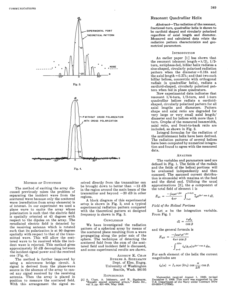
349 COhlNUh‘ICbTIONS Resonant Quadrafilar Helix /EXPERIMENTALPOINT THEORETICAL PATTERN Abstract-Theradiation of theresonant, fractional-turn, quadrafilar helix is shown t o be cardioid shaped and circularly polarized regardless of axial length anddiameter. Measured and calculated data relate the radiation pattern characteristics and geometrical parameters. INTRODUCTION -ioL Fig. 3. .ARIZATIION An earlier paper [l] hasshown t h a t the resonant (element lengt,h = X/2), 1/2turn, antiphase-fed, bifilar helix radiates a sine-shaped, circularly polarized radiat.ion patternwhenthediameter =0.18X and the axial length =0.27X; and that two such bifilar helices, concentric with orthogonal radials (a quadraflar helix), radiate a cardioid-shaped, circularly polarized pattern when fed in phase quadrature. New experimental data indicates that resonant1/4-turn,l/f-turn,and1-turn quadraflar helices radiate a cardioidshaped, circularly polarized patt.ern forall axial lengths and diameters. Pattern shapeand axial ratioaredegradedfor verylarge or verysmallaxiallength/ diameter and forhelices with more than 1 turn. Graphs of the measured beamwidth, axialratio,and front-to-back ratioare included, as shown in Fig. 3. 1nt.egral formulas for the radiation of t h e multielement helix have been derived. The radiation patt.erns of several helices have been computed by numerical integration and found to agree with the measured data. .4KaLrsIs Fig. 4. ceived directly from the t.ransmitter can be brought. down t o bet,ter than -13 dB The method of exciting the array disin theregion around the main beamof t,he cussed previously raises theproblem of transmitter and beyond -20 dB in other separatingtheincidentwavefromthe regions. scattered wave because only the scatt,ered A block diagram of this experiment.al wave (reradiat.ion from array elements) is setup is shown in Fig. 2, andatypical of int.erest,. I n our experiment n e used a experimental radiation pat.tern compared planewaveto excitet.he array whose with t.he theoretical pattern at designed polarization is such that the electric field frequency is shown in Fig. 3. is spat,ially orient.ed a t 45 degrees with respect to the dipoles on the array. The COXCLUSION reradiatedelectric field is detectedby We haveinvestigatedtheradiation the receiving antenna whichis rotat,ed pat.tern of a spherical array by means of such that its polarization is at 90 degrees the scattered plane resulting froma wave spat,ially w-it.hrespect t o t.hat of the transpropagatingalongthepolar axis of the mit.tedwave. Thk will allow the scat.- sphere.Thetechnique of det,ectingthe tered wave to be received while the inciscattered field from the sum of the scatdent wave is rejected. This method gives t.ered field and incident field is discussed, approximately 10 dB decoupling between and some experimental results are shown. the incident signalpower and thereceived ASDREWI(. CHAN one (Fig. 4). RURENS A. SIGELMASN Themethod is furtherimprovedby Dept. of Elec. Engrg. d using microwave a bridge circuit. University of Washington signal is derivedfromthe plane-wave Seattle, Wash. 98105 source in the absence of the array to cancel anysignal received by the receiving I~EFEREKCES antenna.Thenthearray is placedin (11 A. Chan, A. Ishimam, and R. Sige+V, position t o measure t.he scattered field. ’Equallyspacedspherical arrays,” Radw Sa., revol. 3, pp. 4 0 1 4 W , May 1968. With t.his arrangement the signal METHODOF DETECTION T h e variables and parameters used are defined in Fig. 1. The fields of t,he radials and t.he fields of the helical portions d l be evaluat.ed independently and t.hen summed.Theassumedcurrentdistribution is sinusoidal wit,h maxima a t t h efeed andthedistalend.Utilizingtheusual approximations[a],the 4 component of the t.otal field of element 1 is Field of the Helical Portions Let 01 betheintegrationvariable. From Fig. 1 and the general formula is -j w p ~ o e - j l x E’H = 4flCOS6 2xz . Ja=o i+(+,or)ej~r’ +de. For each element of the helix 6he current magnitudes are O1 id(.) = l o c o s (kso) cos -cos 8. 2N Manuscript received August 1. 1968; revised December 2, 1968. This work was supported by the U S . Department of the Navy under Cont.ract NOW 62-0604-C-CFBhl). 350 IEEE TRANSACTIONS ON ANTENNAS ANDPROPAGATION, MAT 1969 1 AXIAL LENGTH = PN P-PITCH LENGTH FOR ONE ELEMENT N=NUMEER OFTURNS FORONE ELEMENT 7 Fig. 1. MB EEAMWIDTH (DEGREES1 60 OT 0 I I I .I .2 .3 3 AXIAL LENGTH (WAVELENGTHS] I ! .5 .6 (a) I/Z TURN Odb 6) 0 (b) Fig. 2. (a) Q u a d r a k helix 1 turn. $=O, P=O.IG, ro=O.OGX. (b) Quadrhelix 1/4 turn. +=O, P=1.36h, ro=O.OSL AXIAL LENGTH (WAVELENGTHS) (C) Fig. 3 Quadrafilar h@x. experimental data. Solid lines % (e) indicate p e k &a1 ratio over t h e henuwhere rn front of helix; dashed lines n d x a t e peak a s dL ratio over 3-dB beamwidth of helix. 351 COMMUNICATIONS Impedance Limited data indicates a variation in at resonancefrom theinputimpedance 70 ohms for the 1/4-turn helix t o 15 ohms for the I-turn helix. For elements 1 and 2: &(+,a) = &(a) cos (4 - a). For e1ement.s 3 and 4: - a). &(+,a) = i9(a)sin (+ -ro cos CY sin e sin Pff +cos e)] 2r The phase term for element 1 is 7 r ’ r T’ cos $ = r = + ro Pa: .sin a sin e sin + + 2a 1/4-turn helix e. C. C. IGLGUS Appl. Phys. Lab. The Johns Hopkins University Silver Spring, Md. da. Field of the Radials If thecurrentontheradials is apa uniformdistribution, proximatedby the following simplified solutions result: r0 cos a sir1 e cos + .COS + REFERENCES [I] C. C. DKilgus, ‘Multielement., fractionalturn helices, I E E E T r a m Antennas and Propagation (Communieafions).vol. AP-16, pp. 499-500, July 1968. [ 2 ] S. A . SchelkunoE. “ A general radiation formula,” Proc. I R E , vol. 27, pp. 660-666. October 1939. Define uplor0 K = cos (kro)e-ikr 4irr Then E+ for the helical portion of element 1 is given by 1/2-turn helix Equatorial Plane Pattern of an Axial-TEM Slot on a Finite Size Ground Plane . sin e cos 4 +ro sin a sin e sin 4 1-turn helix Similarly, the field of element 2 is .cos + (1 + eikP sin 0 cos + -ro sin a sin 0 sin 4 Pol +cos e)] 2r da. Elements 3 and 4 (thesecond bifilar t.0 helix) arefedinphasequadrature, e1ement.s 1 and 2, respectively. T h e fields are - exp [ik ( - r o sin a sin e cos 4 + ro cos (Y sin e sin +cos 91 2r COS 8). Computation Numerical integrat,ion of t.hese expropressions with a digitalcomputer vided the t.heoretica1 patterns of Fig. 2. The measured patterns plotted for comparison were taken under the conditions outlinedinthe following section. T h e experimental patterns are circularly polarized for all e and +, indicating that EO has the same shape asE+. EXPERINENTAL DATA + Radiation Patterns These details are common in the data of Fig. 3: Pff The c0ncept.s of edge diffraction have been used to compute the scattered and radiated fields of waveguidegeometries [1]-[2]. They can also be used to predict theperturbat.ions in the patterns introduced by such features as the edges of a ground plane. Lopez [3] hasobtained a rather inaccurate result for the case of a monopoleover a circularground plane. Ryan and Peters [4] have introduccd an equivalent current concept to demonstrate that good accuracy can be obtained for this case. This communication considers a TEMmodeaxiallyslottedgroundplane of finite width and lengt,h, as shown i n Fig. 1. T h e diffractions from the edges of the ground plane and their contributions to t h e overall pattern are shown in thecomputed results. The radiation-pattern calculation will consist of the superposition of raysemanatingfromtheaperture the additional (wedges 1 and 2) and diffractedraysfrom wedges 3-6 when added in proper relative phase. T o check t h e va1idit.y of thetechnique, experimentalresultsareusedforcomparison since rigorous solut.ions do not exist. The total diffracted field from wedges 1 and 2 includingsecond-andhigher order diffractions [l], [2] is given by e--j(kro+z/4) ED(TO,+O) = -=- measurementfrequency 400 MHz element diameter 0.1 inch element length 16.0 inches feed orthogonal folded baluns; power division and phase quadrature obtained with a directional coupler v‘2rkro mechanical support 0.625-inch diameter aluminum tube provides shieldand a shortingpoint for thedistalends elements geometry L, = ~ N+/- RD(+o) (1) where a balun of t h e 1 (16.0“ - 2r0)? - 4r2r02. N! Manuscript received September 4, 1968; revised January 13, 1969.
