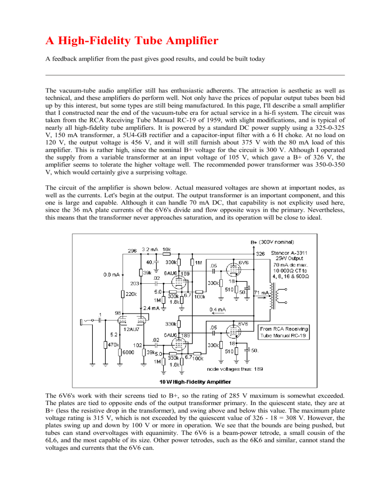
A High-Fidelity Tube Amplifier A feedback amplifier from the past gives good results, and could be built today The vacuum-tube audio amplifier still has enthusiastic adherents. The attraction is aesthetic as well as technical, and these amplifiers do perform well. Not only have the prices of popular output tubes been bid up by this interest, but some types are still being manufactured. In this page, I'll describe a small amplifier that I constructed near the end of the vacuum-tube era for actual service in a hi-fi system. The circuit was taken from the RCA Receiving Tube Manual RC-19 of 1959, with slight modifications, and is typical of nearly all high-fidelity tube amplifiers. It is powered by a standard DC power supply using a 325-0-325 V, 150 mA transformer, a 5U4-GB rectifier and a capacitor-input filter with a 6 H choke. At no load on 120 V, the output voltage is 456 V, and it will still furnish about 375 V with the 80 mA load of this amplifier. This is rather high, since the nominal B+ voltage for the circuit is 300 V. Although I operated the supply from a variable transformer at an input voltage of 105 V, which gave a B+ of 326 V, the amplifier seems to tolerate the higher voltage well. The recommended power transformer was 350-0-350 V, which would certainly give a surprising voltage. The circuit of the amplifier is shown below. Actual measured voltages are shown at important nodes, as well as the currents. Let's begin at the output. The output transformer is an important component, and this one is large and capable. Although it can handle 70 mA DC, that capability is not explicity used here, since the 36 mA plate currents of the 6V6's divide and flow opposite ways in the primary. Nevertheless, this means that the transformer never approaches saturation, and its operation will be close to ideal. The 6V6's work with their screens tied to B+, so the rating of 285 V maximum is somewhat exceeded. The plates are tied to opposite ends of the output transformer primary. In the quiescent state, they are at B+ (less the resistive drop in the transformer), and swing above and below this value. The maximum plate voltage rating is 315 V, which is not exceeded by the quiescent value of 326 - 18 = 308 V. However, the plates swing up and down by 100 V or more in operation. We see that the bounds are being pushed, but tubes can stand overvoltages with equanimity. The 6V6 is a beam-power tetrode, a small cousin of the 6L6, and the most capable of its size. Other power tetrodes, such as the 6K6 and similar, cannot stand the voltages and currents that the 6V6 can. The power output is the product of the voltage and current swings, divided by 8. The plate efficiency is the output power divided by the product of the quiescent voltage and current. Another parameter often used is the power sensitivity of an amplifier, which is the output power divided by the square of the rms input grid voltage (units of conductivity, siemens). Cathode bias is used, which means that there is considerable plate current in the quiescent state, in this case 36 mA. The amplifier is classed as AB1, which means that plate current flows in the quiescent state, and the grids never are driven positive. The tubes may be driven to cutoff in the other direction, however. It's obvious that there are two identical amplifiers, tied to the opposite ends of the output primary, working in push-pull. The emphasis here is not on efficiency, but on fidelity. There is no hint of crossover distortion, and even-order nonlinearities are cancelled by the push-pull connection. The quiescent plate dissipation is 11.7 W, close to the rating of 12 W. These tubes are indeed being used close to their limits. The great advantage of the beam power pentode is that very little drive power is required. In fact, with class AB1 operation, only voltage is required. If we were using power triodes (and these are very popular) considerable power could be necessary to drive the grids. Here, however, the 6V6's are driven by 6AU6 pentodes operating at a very small plate current with large plate resistors, and a grid bias of -1.7 V. The plate voltages are only some 182 V, and the screens are supplied through a 1M resistance, so these tubes are well within their maximum voltage ratings. This is a feedback amplifier, and the bias for the 6AU6's is not supplied by the small cathode current, but by feedback from the plates of the 6V6's, which holds the cathodes of the 6AU6's at 6.7V. The feedback ratio is about 56, which sets the voltage gain of the amplifier, by the usual rule. A voltage divider, consisting of the 330k and 1M resistors, supplies the grids with the proper bias. The open-loop gain of the 6AU6 stages is about 165, while the gain of the 6V6 output stages is about 15, making a loop gain of 165 x 15 / 56 = 44. The effect of the feedback is to hold the voltage gain at 56 (grid of 6AU6 to plate of 6V6), and to decrease any nonlinearities by a factor of 44. This means that the amplifier is indeed very linear, with constant gain, over a wide frequency band. Feedback is far more effective in achieving linearity than any selection of tubes. Fidelity is not limited by the amplifier; the loudspeaker and signal source are far more limiting, and must be considered in relation to the amplifier, which must compensate for their deficiencies. Since the feedback network consists of only resistors, the gain will be independent of frequency. This is quite important, since the impedance of a loudspeaker is not constant, but varies with frequency, and the resistance reflected back to the output tubes affects the gain. A triode is a voltage source, with low plate impedance, so its gain is less affected by the load than that of a pentode, which is a current source, as is a transistor. Remember that the gain is gm(rp||RL). The triode gain is dominated by its plate resistance, while the pentode gain is dominated by the load resistance. Triodes were preferred for output stages for this reason, though feedback is a much better and more efficient solution. An output triode should have high transconductance and low plate resistance, which implies a low amplification factor. Compensating networks containing capacitors can also be used to reduce the gain at high frequencies in pentode circuits. The general idea is to make the gain at 1000 Hz equal to the gain at 400 Hz, to ensure rough constancy of gain over the most important frequencies. The input circuit, built around the 12AU7, has extra power supply filtering provided by the 10k resistance and 40 F capacitor. The heavy fluctuating current demands of the output stage can affect the B+ voltage, and feed back to the low-level input stages if decoupling is not provided. The first half of the 12AU7 accepts the input voltage and translates it to a higher voltage with small gain. The unbypassed 6800 resistor provides stabilizing negative feedback. This circuit could be replaced by a simple voltage divider, but the triode gives better impedances and uses less current. The other half of the 12AU7 is a phasesplitter. When its grid rises in potential, the cathode follows. Note that the grid bias is about -4 V. The same change in current is felt by the other 39k resistance, and the plate falls by an exactly equal amount. These changes are of the order of a volt only, and are fed through the .02 F capacitors to the grids of the 6AU6's. The plate voltages on the 12AU7 are also well within limits. The 6V6's are the only tubes exposed to high voltages, and they appear rugged enough to handle them. When I initially measured the node voltages, I could not get consistent results for the currents in the plates and cathodes of the two triodes. The problem turned out to be the resistor values, two of which were certainly well out of specifications. The 220k resistor measured 260k, and the lower 39k resistor measured 43k. The other resistors were close to their marked values. Modern resistors would be much more accurate. I used the amplifier to drive an 8 Realistic speaker rated at 40 W (max), and it was easy to put out enough power to make the speaker definitely uncomfortable. Perhaps the 40 W is an optimistic rating. The earphone output of a small transistor radio provided output of surprising quality. My amplifier was built on an aluminum chassis, 5" x 9.5" x 3" using turret sockets for the miniature tubes (these combined the socket with tie points). There are paper capacitors (Sprague "Black Beauty" and Astron "Hy-Met" waxed ones), electrolytics (Sprague "Atoms" and Herald axial), and 5% carbon composition resistors of what seems ample power rating. The 100k feedback resistors are each two 200k wire-wound precision resistors in parallel, but the 1800 resistors are normal 1/2W 5%. All the components could be replaced by improved modern types of smaller size and greater reliability, but the turret sockets are no longer available. Nevertheless, everything works well, and the circuit could be duplicated today. In fact, everything is available from Antique Electronic Supply (see the page on Vacuum Tubes for a link), including a T-1609 output transformer from Hammond. This is a 10W transformer, not the 25W transformer I used, but will be completely adequate. A 10x6x2 aluminum chassis should be adequate. Use good 1W metal-film resistors throughout, except for the cathode resistors of the 6V6's, which should be 2W. The 100k feedback resistors should be 2W, 1% resistors, and the 1.8k resistors 1W, 1%. Coupling capacitors should be 600V, cathode bypass electrolytics 50V, and the decoupling capacitor 450V. For the power supply, I would recommend a 275-0-275 V, 150 mA transformer (Hammond T-270FX) and a 7H, 150 mA filter choke (Hammond T159Q) with a 50/50 F at 500V electrolytic, on the same size chassis. Use silicon rectifier diodes (1N4007), or, for historical accuracy, a 5Y3GT rectifier. All the tubes, except the 6AU6's, are currently being manufactured. The current prices for vacuum tubes reflect the demand for output tubes, and, as has been mentioned, some are even still currently manufactured. The beam power tube is most often used. If more power than a 6V6 can provide is desired, the 6L6, or the more recent 7027 are good choices, supplying up to about 40 W. The Mullard types KT66 and KT88 have long been famous, in this range. For still more power, small transmitting tubes can be used, such as the 807 and the slightly smaller 807W, or their 12.6 V heater equivalents, the 1625 and the 5933, respectively. The 1625 is available at a very low price, and would be an excellent choice. It was widely used by the military in WWII, and available as surplus in great quantities. Some people, however, prefer the older power triode. The prices of all of these are notably high. The venerable 2A3 is roughly equivalent to the 6V6, and commands a very high price. There is also the 300B, about which I have no information. Tubes can be connected in parallel for greater output, which is popular with triodes, though it is usually better simply to use a larger tube when possible. The triodes could be preferred for their appearance, but also, it seems, because they are more linear than pentodes. However, feedback destroys this advantage, and any amplifier with feedback is better than any amplifier without. For high-power amplifiers, the difficult component to find is probably the output transformer, which may easily cost more than the tubes.
