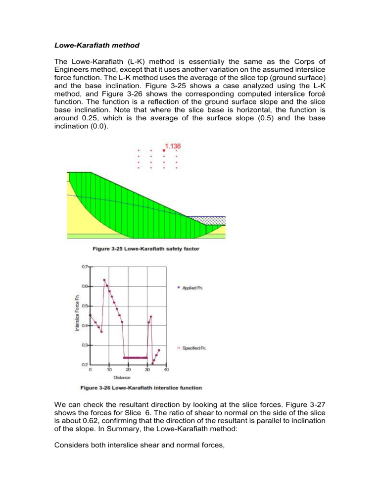
Lowe-Karafiath method The Lowe-Karafiath (L-K) method is essentially the same as the Corps of Engineers method, except that it uses another variation on the assumed interslice force function. The L-K method uses the average of the slice top (ground surface) and the base inclination. Figure 3-25 shows a case analyzed using the L-K method, and Figure 3-26 shows the corresponding computed interslice forcé function. The function is a reflection of the ground surface slope and the slice base inclination. Note that where the slice base is horizontal, the function is around 0.25, which is the average of the surface slope (0.5) and the base inclination (0.0). We can check the resultant direction by looking at the slice forces. Figure 3-27 shows the forces for Slice 6. The ratio of shear to normal on the side of the slice is about 0.62, confirming that the direction of the resultant is parallel to inclination of the slope. In Summary, the Lowe-Karafiath method: Considers both interslice shear and normal forces, Satisfies overall horizontal force equilibrium, but not moment equilibrium, and Uses interslice force functions related to the ground surface slope and slip surface inclination. The Janbu Generalized method is actually similar to the Corps of Engineers and Lowe-Karafiath methods. All these methods consider both interslice shear and normal forces, but satisfy only force equilibrium. The Janbu Generalized method just uses a different technique to relate the interslice shear forces to the normal forces. The Lowe & Karafiath method (1960) and the Corps of Engineers (COE) method (1968) generally gave values of factor of safety which were too high (unconservative) for homogeneous slopes. The Corps of Engineers method generally gave values which were higher (less conservative) than the Lowe & Karafiath (LK) method. Método de Lowey Karafiath El método de Lowe y Karafiath (1960) es prácticamente idéntico al del cuerpo de ingenieros con la excepción las direcciones de las fuerzas entre partículas varían de borde a borde en cada dovela. Su resultado es menos preciso que los que satisfacen resultado es menos preciso que los que satisfacen equilibrio completo y al igual que el método del cuerpo de ingenieros es muy sensitivo a la inclinación supuesta de las fuerzas entre partículas. Si se varía el ángulo de estas fuerzas se varía substancialmente el a substancialmente el factor de seguridad. Factor de seguridad. Para determinar si una ladera o talud es estable bajo las condiciones que prevalecen en un determinado sitio, generalmente se utiliza el término factor de seguridad, el valor aceptable del mismo se selecciona tomando en cuenta las consecuencias o riesgos que podría causar el deslizamiento. En laderas y taludes suele adoptarse valores que oscilan entre 1.2 y 1.5 o incluso superiores, dependiendo de la confianza que se tenga en los datos geotécnicos a utilizar en el análisis, así como en la información disponible sobre los factores condicionantes y desencadenantes que influyen en la estabilidad. En términos generales el factor de seguridad se puede definir como el cociente entre la resistencia al corte en la superficie de deslizamiento y el esfuerzo requerido para mantener el equilibrio estricto de la masa deslizante como se muestra en la ecuación 1.1. Otra forma de expresar esta definición es: "el factor por el que la resistencia a cortante del suelo tendría que ser dividida para que el talud esté en un estado de equilibrio límite o de inminente falla”. Lowe (1976) señaló que es lógico definir el factor de seguridad en función de la resistencia cortante, por ser precisamente la resistencia al corte, el parámetro que involucra mayor grado de incertidumbre en el análisis de la estabilidad. Sin embargo, algunos autores definen en factor de seguridad en función del equilibrio de momentos resistentes y actuantes en la masa de suelo o roca en inminente falla, o incluso de la altura del talud o ladera (Winterkorn, 1987). Wright (1973) y Tavenas (1980), demostraron que el factor de seguridad real varía en cada punto a lo largo de la superficie de rotura, mientras que en la mayoría de los análisis de equilibrio se supone que es constante. Sin embrago, Chugh (1986) comprobó que para fines prácticos es aceptable asumir el valor medio para dicho factor de seguridad, a lo largo de la curva de rotura. Limit equilibrium method is done by comparing the previously developed methods: Ordinary /Fellenius, simplified Bishop method, Janbu simplified method, Spencer Method, Morgenstern-Prince method, Lowe-Karafiath Method. Both LEM and FEM analysis are performed using computer program. Comparison of the results of the Safety factor of the methods mentioned above will then be compared again with the real landslide case on the field. Expected outcomes of this research are: a) Obtain tolerance Safety Factor difference value with the above methods on various conditions of sliding, b) Obtain the method that are suitable with the conditions of sliding
