Gas Treating Process Overview: Requirements & Specifications
Anuncio

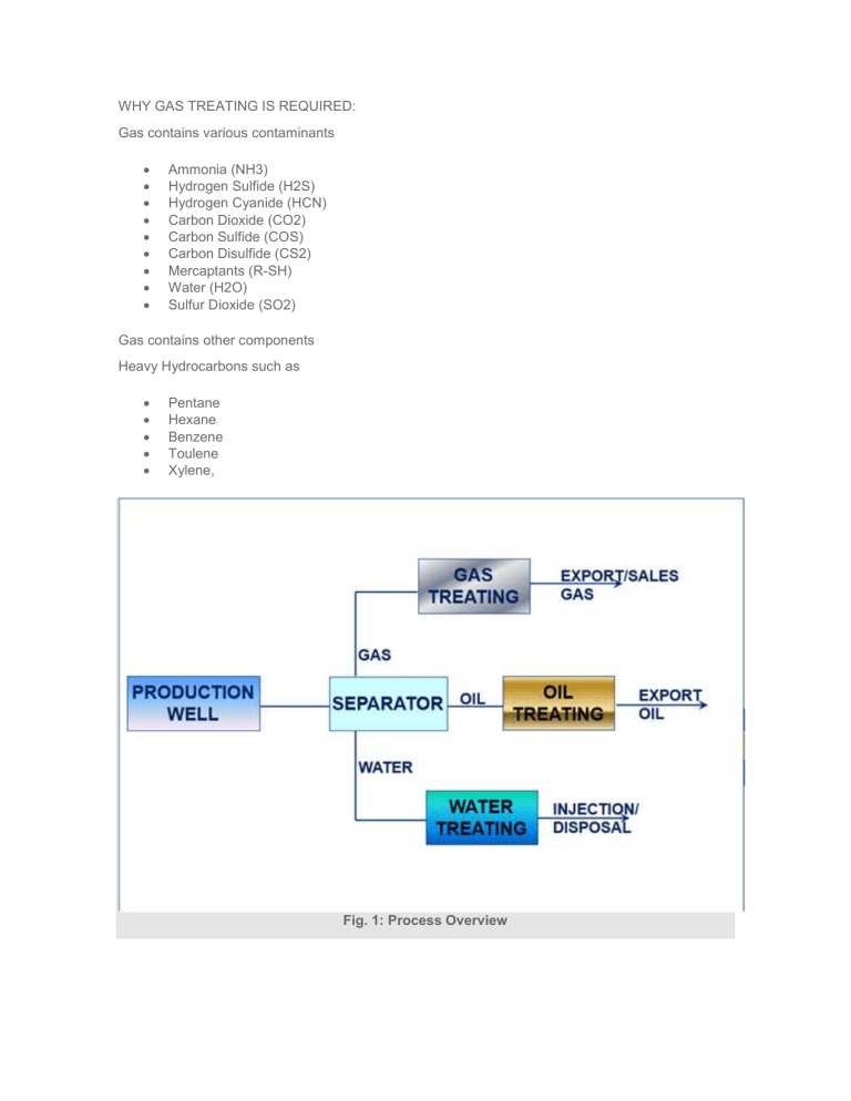
WHY GAS TREATING IS REQUIRED: Gas contains various contaminants Ammonia (NH3) Hydrogen Sulfide (H2S) Hydrogen Cyanide (HCN) Carbon Dioxide (CO2) Carbon Sulfide (COS) Carbon Disulfide (CS2) Mercaptants (R-SH) Water (H2O) Sulfur Dioxide (SO2) Gas contains other components Heavy Hydrocarbons such as Pentane Hexane Benzene Toulene Xylene, Fig. 1: Process Overview Removal of these contaminants are required for reason of : Corrosion Control Toxicity Gas product specifications To prevent poisoning of catalyst in downstream facilities Control of the overall heating value of the natural gas To meet environmental requirements To prevent freeze out at low temperatures To prevent hydrate formation CO2 & H2S are very common contaminants in Natural Gas System CO2: When combined with water forms Carbonic Acid which is corrosive CO2 reduces the BTU value of the gas If present in 2-3% gas is not saleable. H2S: Extremely toxic gas Highly corrosive Mercaptants (R-SH): It has smell If comes in contact with bacteria (inside the final product storage) then released H2S 2R-SH Bacteria R-SSR + H2S EXPORT GAS SPECIFICATION: Specification Units Maximum Minimum Gross Heating Valve Btu/scf 1154 940 Carbon Dioxide Mole % 1 — Nitrogen Mole % 2 — Hydrogen Sulphide ppm vol 5 — Mercaptan Sulphur Content ppm vol 5 — Oxygen ppm 25 — Moisture Content lb/MMSCF 10 — Max Water Dew Point °C 2(at delivery pressure) — Max. Hydrocarbon Dew Point °C -2(at delivery pressure) — Fig. 2: Specification of Export Gas Typical Sales Gas Specifications: Fig. 3: Sales gas Specification Typical LNG Product Specifications: Fig. 4: LNG product Specification GAS TREATING STEPS: 1. Gas Sweetening (Removal of H2S, CO2, etc) 2. Gas Dehydration (Removal of Water) 3. Gas Dew Pointing (Removal of Heavy Hydrocarbons) GAS TREATING: Fig. 5: Gas Treating GAS SWEETENING: DIFFERENT TYPE OF PROCESS Chemical Solvent Physical Solvent Chemical + Physical Solvent Solid Bed Direct Conversion Acid Gas Removal Processes: Chemical Solvent Physical Solvent Dire MEA (Mono Ethanol Amine) Selexol® Iron DEA (Di-ethanol Amine) Rectisol Stre TEA (Tri-ethanol Amine) Purisol Uni MDEA (Methyl Diethanol Amine) Spasolv Tak DIPA/Shell ADIP® Propylene Carbonate LO- DGA/Fluor Econamine® Estasolven Lac Proprietary Amine Alkazid Tow Benfield (Hot Carbonate) Sulf Catacarb (Hot Carbonate) Giammarco-Vetrocoke (Hot Carbonate) Diamox Dravo/Still Fig. 6: Acid Gas removal Process Gases removed by different processes: Process Gases Removed CO2 H2S RHS COS X X SOLID BED Iron Sponge X SulfaTreat X Zinc Oxide X Molecular Sieves X X MEA – mono ethanol amine X X X* DEA – diethanol amine X X X CHEMICAL SOLVENTS MDEA – methyl diethanol amine X DGA – diglycol amine X X X DIPA – di isopropanol amine X X X Hot Potassium Carbonate X X X Proprietary Carbonate Systems Fig. 7: Gases removed by different process Process Capabilities for Gas Treating: Normally Capable of Meeting 1/4 Grain H2S Removes Mercaptans and COS Sulfur Selective H2S Removal Solution Deg Monoethanolamine Yes Partial No Yes (COS, C Diethanolamine Yes Partial No Some (COS, Diglycolamine Yes Partial No Yes (COS, C Methyldiethanolamine Yes Slight Yes No Sulfinol® Yes Yes Yes Some (CO2, Selexol® Yes Slight Yes No Hot Pot – Benfield Yes No No No Fluor Solvent No No No No Iron Sponge Yes Partial Yes –– Mol Sieve Yes Yes Yes –– Stretford Yes No Yes CO2 at high c LO-CAT® Yes No Yes CO2 at high c Chemsweet Yes Partial for COS Yes No Fig. 8: Gas Sweetening GAS DEHYDRATION: Glycol Dehydration Solid Desiccant Dehydration Fig. 9: Gas Dehydration GAS DEW POINTING: Propane Refrigeration J-T Refrigeration Turbo Expander Fig. 10: Refrigerated J T Process