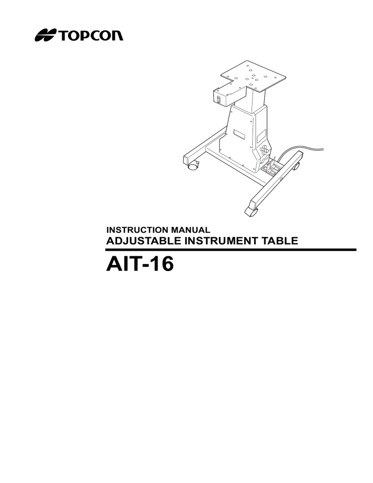
INSTRUCTION MANUAL ADJUSTABLE INSTRUMENT TABLE AIT-16 INTRODUCTION Thank you for purchasing the TOPCON AIT-16 Adjustable Instrument Table. Purpose of use • This table enhances the operability of the equipment which is loaded on it. This adjustable instrument table has the following features: • The equipment loaded on this table can be moved up and down smoothly according to the height of the patient's eyes. • Ample leg room is provided, so the patient can sit in a comfortable position during the examination. This Instruction Manual describes the TOPCON AIT-16 Adjustable Instrument Table, including the outline, operation, trouble shooting, inspection, maintenance and cleaning. To get the best usage from this table, carefully read "DISPLAY FOR SAFE USE" and "SAFETY PRECAUTIONS". Keep this manual at hand for future reference. Storage method 1. Environmental conditions Temperature: 10 ~ 40°C Humidity: 35 ~ 85% Air pressure: 700 ~1060 hPa 2. When storing the table, adhere to the following conditions: (1) Do not splash this table with water or store it in a place that is close to a water supply. (2) Store this table in a place where it is not adversely affected by air pressure, temperature, humidity, ventilation, sunlight, dust, salty/sulfurous air, etc. (3) Keep this table stable without inclination, vibration, shock, etc. (not only during storage but also in transportation). (4) Do not store this table where chemicals are stored or gas is generated. Safety precautions • Before using this table, connect all the power cords correctly. • Use the power supply 120Vac ± 10% (50/60Hz ± 1Hz). • Shape of plug USA 120V/60Hz Type A (Hospital Grade) Canada 120V/60Hz Type A (Hospital Grade) • When this table is not used over a long period of time, remove the plug from the outlet. 1 DISPLAY FOR SAFE USE In order to encourage the safe use of products and prevent any danger to the operator or others or damage to property, important warnings are put on the products and inserted into the instruction manuals. We suggest that everyone understand the meaning of the following displays and icons before reading the "SAFETY PRECAUTIONS" and text. DISPLAY Display Meaning WARNING CAUTION Improper handling or ignoring this display may lead to the serious injury or death. Improper handling or ignoring this display may cause personal injury or physical damage. • Injury refers to cuts, bruises, burns, electric shock, etc. • Physical damage refers to extensive damage to a building(s), peripheral equipment and/or furniture. ICON Icon Meaning This icon indicates Prohibition. Specific contents are shown with words or an illustration located next to the icon. This icon indicates Mandatory Action. Specific contents are shown with words or an illustration located next to the icon. This icon indicates Hazard Alert (Warning). Specific contents are shown with words or an illustration located next to the icon. The appliance is employing a "hospital grade" attachment plugs. Grounding reliability can only achieved when the equipment is connected to an equivalent receptacle marked "hospital Grade" or "hospital Only". 2 SAFETY PRECAUTIONS WARNING Icons Prevention Item Page Do not disassemble, modify or repair this adjustable instrument table. You may receive an electric shock. Ask your dealer to repair it. 11 Do not splash this adjustable instrument table with water or any other liquid. A fire or electric shock may occur as a result. ----- Connect the power plug to the 3-core AC outlet (with grounding). If the table is not grounded and an electric leak occurrs, a fire or electric shock may result. 10 Turn off the power switch (main switch) and remove the power cord from the outlet before replacing the fuses. If you do not follow this procedure, you may receive an electric shock. Replace the fuses with the specified rated ones. 17 If smoke comes from this adjustable instrument table, immediately turn off the power switch (main switch) and remove the power plug from the outlet. If you keep operating the table without solving this problem, a fire may occur. Ask your dealer to repair it. 10 CAUTION Icons Prevention Item Page Don't incline the device by more than 10° when it is on the adjustable instrument table. The table may tip over. 5 Don't put your fingers between the movable units when the main unit is in use. Your fingers may become caught, causing an injury. 10 Make sure the table fixation bolts are tightened securely. When a bolt becomes loose, the tabletop may come off, causing the loaded equipment to fall off and cause an injury. 5 Make sure the leg fixation bolts are tightened securely. When a bolt becomes loose, the leg unit may come off, causing the main unit to tip over and cause an injury. 5 To prevent electric shock, do not remove the cover. Ask the service personnel to repair your adjustable instrument table. 11 18 Use the accessory fuse. If other fuses are used, the adjustable instrument table may malfunction and cause a fire. 17 3 Icons Prevention Item Page Don't place the adjustable instrument table on a slope or in an unstable place. The table and the loaded devices may tip over or fall off and cause an injury. ----- This instrument has been tested (with 120V/230V) and found to comply with IEC60601-1-2: 1993. This instrument radiates radio frequency energy within standard and may affect other devices in vicinity. If you have found out by turning on/off the instrument that it affects other devices, it is recommended to change the direction, keep a proper distance against other devices or change the outlet. If you have a question, consult with the selling agent. ----- MAINTENANCE USER MAINTENANCE To maintain the safety and performance of the equipment, never attempt to do the maintenance on your own. Ask our service personnel to repair the adjustable instrument table except for the items specified here. These are the exceptions and can be performed by the user. For details, follow the instructions outlined below. Replacement of fuse The fuse of the main unit can be replaced with a new one. For details, refer to "Replacement of fuse" on P. 17. ESCAPE CLAUSE • TOPCON shall take no responsibility for damage due to fire, earthquakes, actions by third persons or other accidents, or the negligence and misuse of the user and use under unusual conditions. • TOPCON shall take no responsibility for damage derived from the use or inability to use this equipment, such as a loss of business profit and/or suspension of business. • TOPCON shall take no responsibility for damage caused by usage other than that described in this Instruction Manual. • TOPCON shall take no responsibility for the result of diagnosis using this equipment. A doctor must take full responsibility for the medical treatment. 4 WARNING INDICATIONS AND POSITIONS For safety purposes, this equipment includes clearly labeled warnings. Correctly use the equipment following these warning instructions. If any of the following marking labels are missing, please contact your dealer or your local TOPCON office listed on the back cover. CAUTION Make sure the table fixation bolts are tightened securely. When a bolt becomes loose, the tabletop may come off, causing the loaded equipment to fall off and cause an injury. CAUTION Don't more the table. incline the device by than 10° when it is on adjustable instrument The table may tip over. CAUTION Make sure the leg fixation bolts are tightened securely. When a bolt becomes loose, the leg unit may come off, causing the main unit to tip over and cause an injury. 5 CONTENTS INTRODUCTION ....................................................................................................................................... 1 DISPLAY FOR SAFE USE ..................................................................................................................... 2 SAFETY PRECAUTIONS ....................................................................................................................... 3 MAINTENANCE ........................................................................................................................................ 4 USER MAINTENANCE ....................................................................................................................... 4 ESCAPE CLAUSE ................................................................................................................................... 4 WARNING INDICATIONS AND POSITIONS ..................................................................................... 5 NOMENCLATURE AND FUNCTIONS NOMENCLATURE AND FUNCTIONS ................................................................................................ 7 STANDARD ACCESSORIES .............................................................................................................. 8 HOW TO USE ASSEMBLY PROCEDURE ................................................................................................................. 9 INSTALLATION OF DEVICE ............................................................................................................ 10 OPERATION ..................................................................................................................................... 10 TROUBLE SHOOTING TROUBLE SHOOTING GUIDE ......................................................................................................... 11 REFERENCE MATERIALS OPTIONAL ACCESSORIES ............................................................................................................. 12 SPECIFICATIONS AND PERFORMANCE ....................................................................................... 12 CLASSIFICATION ............................................................................................................................. 12 ELECTROMAGNETIC COMPATIBILITY .......................................................................................... 13 MAINTENANCE AND INSPECTION INSPECTION .................................................................................................................................... 17 MAINTENANCE ................................................................................................................................ 17 CLEANING ........................................................................................................................................ 18 PERIOD OF USE AND DISPOSITION ............................................................................................. 18 6 NOMENCLATURE AND FUNCTIONS NOMENCLATURE AND FUNCTIONS Up-and-down switch Table fixation bolt Support Main switch Fuse Base Caster Spare receptacle Leg fixation bolt Up-and-down switch: Used to move the table up and down. Support: The table is mounted on its top. Base: The leg unit is attached to it by means of the center column. Spare receptacle: Used to supply power for a loaded device. Main switch: This is the power switch of the main unit. Caster: Used to move this table. Locking/unlocking can be changed. 7 NOMENCLATURE AND FUNCTIONS STANDARD ACCESSORIES The standard accessories are shown below. Check to see if all of them are included. The numerals in parentheses show the quantity. Instruction manual (1) INS Makeup button (2) AD J TR U AIT USTACBTLION MA -16 E INSNTUAL RU ME NT TA B LE Fuse (2) 5A-125V (2) 10A-125V Hexagonal socket bolt M6 × 20 With SW (4) Hexagonal socket bolt M8 × 30 With SW (2) Hexagonal wrench for M8 (1) Hexagonal wrench for M6 (1) If any of the standard accessories are missing, contact your local TOPCON office. 8 NOMENCLATURE AND FUNCTIONS HOW TO USE ASSEMBLY PROCEDURE 1 Attach the legs to the base. The casters must be positioned diagonally against both the patient and the operator. To attach the legs, use the two accessory M8 hexagonal socket bolts (with spring washers). Securely tighten and affix the bolts. 2 Push the makeup button into the M8 hole of the leg (follow the same procedure for both the right and the left leg). 3 Set the tabletop in place. Set the tabletop in place so that the φ50mm hole (for arranging the cord) is at the opposite side of the up-and-down switch. To attach the tabletop, use the four accessory M6 hexagonal socket bolts (with spring washers). Securely tighten and affix the bolts. * Do not use any other tabletop except for the one included with the AIT-16 Instrument Table. 4 Set the adjustable instrument table in the specified position. There is a hole to pass the power cord through at the center of the table. When loading a device onto the table, pass the cord through this hole beforehand. Spring washer M8 hexagonal socket bolt Makeup button 9 HOW TO USE INSTALLATION OF DEVICE Make sure that the loaded device is set at the specified position. Refer to each setup manual for details on connecting the cable wiring. OPERATION WARNING If smoke comes from this adjustable instrument table, immediately turn off the power switch (main switch) and remove the power plug from the outlet. If you keep operating the table without solving this problem, a fire may occur. Ask your dealer to repair it. WARNING Connect the power plug to the 3-core AC outlet (with grounding). If the table is not grounded and an electric leak occurrs, a fire or electric shock may result. CAUTION Don't put your fingers between the movable units when the main unit is in use. Your fingers may become caught, causing an injury To operate this adjustable instrument table smoothly, follow the procedure outlined below. 1 Turn the main switch off. Main switch ER W PO 2 3 4 5 Insert the power cord into the specified outlet. Turn the main switch on. Let the patient sit down at the center of the loaded instrument table. Set the table to the proper height with the up-and-down switch according to the patient's posture. Up-and-down switch The table moves up and down by pressing the up-and-down switch. 10 HOW TO USE TROUBLE SHOOTING TROUBLE SHOOTING GUIDE Trouble shooting guide WARNING Do not disassemble, modify or repair this adjustable instrument table. You may receive an electric shock. Ask your dealer to repair it. CAUTION To prevent electric shock, do not remove the cover. Ask the service personnel to repair your adjustable instrument table. If the instrument table is not functioning properly, check the conditions in the check list below. If the problem is not resolved by following the instructions or if there is no relevant item in the "Symptom" column of the check list, contact your local TOPCON office listed on the back cover of this manual. Check list Symptom Condition Remedial measure Page The table does not move up and down. The power cord has come out of the outlet. Insert the power plug securely. 10 The main switch is not turned on. Turn the main switch on. 10 The fuse has blown out. Refer to "Replacement of fuse". 17 11 TROUBLE SHOOTING REFERENCE MATERIALS OPTIONAL ACCESSORIES Table (AIT-16) : This is a standard table with dimensions of "500 (W) × 490 (D)". Special table (AIT-11) : This is a large table with dimensions of "800 (W) × 500 (D)". In general, it is used to load two devices onto the tabletop. SPECIFICATIONS AND PERFORMANCE 1. Performance Dimensions of main unit Type A : 525 (W) × 490 (D) × 660 ~ 880 (H) mm Weight : 23kg (Weight of main unit) Allowable load weight : 50kg Power supply voltage and frequency : 120Vac, 50/60Hz Power supply input : 220VA Short-time operation : 2min Subject to change in performance and/or appearance without advance notice for future product improvement. CLASSIFICATION • The type of protection against electric shock: Class I equipment • The mode of operation: continuous operation • Not AP or APG equipment 12 REFERENCE MATERIALS ELECTROMAGNETIC COMPATIBILITY This product conforms to the EMC Standard (IEC 60601-1-2:2001). a) MEDICAL ELECTRICAL EQUIPMENT needs special precautions regarding EMC and needs to be installed and put into service according to the EMC information provided in the ACCOMPANYING DOCUMENTS. b) Portable and mobile RF communications equipment can affect MEDICAL ELECTRICAL EQUIPMENT. c) The use of ACCESSORIES, transducers and cables other than those specified, with the exception of transducers and cables sold by the manufacturer of the EQUIPMENT or SYSTEM as replacement parts for internal components, may result in increased EMISSIONS or decreased IMMUNITY of the EQUIPMENT or SYSTEM. d) The EQUIPMENT or SYSTEM should not be used adjacent to or stacked with other equipment. IF adjacent or stacked use is necessary, the EQUIPMENT or SYSTEM should be observed to verify normal operation in the configuration in which it will be used. Guidance and manufacturer's declaration - electromagnetic emissions The AIT-16 is intended for use in the electromagnetic environment specified below. The customer or the user of the AIT-16 should assure that it is used in such an environment. Emissions test RF emissions CISPR 11 RF emissions CISPR 11 Compliance Electromagnetic environment - guidance Group 1 The AIT-16 uses RF energy only for its internal function. Therefore, its RF emissions are very low and are not likely to cause any interference in nearby electronic equipment. Class B The AIT-16 is suitable for use in all establishments, including domestic establishments and those directly connected to the public low-voltage power supply network that supplies buildings used for domestic purposes. 13 REFERENCE MATERIALS Guidance and manufacturer's declaration - electromagnetic immunity The AIT-16 is intended for use in the electromagnetic environment specified below. The customer or the user of the AIT-16 should assure that it is used in such an environment. IEC 60601 test level Immunity test Electrostatic discharge (ESD) IEC 61000-4-2 Electrical fast transient/burst IEC 61000-4-4 Surge IEC 61000-4-5 Voltage dips, short interruptions and Voltage variations on power supply input lines IEC 61000-4-11 Power frequency (50/60 Hz) magnetic field IEC 61000-4-8 Compliance level Electromagnetic environment guidance Floors should be wood, concrete or ceramic tile. If floors are covered with synthetic material, the relative humidity should be at least 30%. ± 6 kV contact ± 6 kV contact ± 8 kV air ± 8 kV air ± 2 kV for power supply lines ± 2 kV for power supply lines ± 1 kV for input/output lines ± 1 kV for input/output lines ± 1 kV differential mode ± 1 kV differential mode ± 2 kV common mode ± 2 kV common mode <5% Ut (>95% dip in Ut) for 0.5 cycle 40% Ut (60% dip in Ut) for 5 cycles 70% Ut (30% dip in Ut) for 25 cycles <5% Ut (>95% dip in Ut) for 5 sec <5% Ut (>95% dip in Ut) for 0.5 cycle 40% Ut (60% dip in Ut) for 5 cycles 70% Ut (30% dip in Ut) for 25 cycles <5% Ut (>95% dip in Ut) for 5 sec Mains power quality should be that of a typical commercial or hospital environment. If the user or the AIT16 requires continued operation during power mains interruptions, it is recommended that the AIT-16 be powered from an uninterruptible power supply or battery. 3 A/m Power frequency magnetic fields should be at levels characteristic of a typical location in a typical commercial or hospital environment. 3 A/m Mains power quality should be that of a typical commercial or hospital environment. Mains power quality should be that of a typical commercial or hospital environment. NOTE Ut is the a.c. mains voltage prior to application of the test level. 14 REFERENCE MATERIALS Guidance and manufacturer's declaration - electromagnetic immunity The AIT-16 is intended for use in the electromagnetic environment specified below. The customer or the user of the AIT-16 should assure that it is used in such an environment. IEC 60601 Compliance Electromagnetic environment Immunity test test level level guidance Portable and mobile RF communications equipment should be used no closer to any part of the AIT-16, including cables, than the recommended separation distance calculated from the equation applicable to the frequency of the transmitter. Conducted RF IEC 61000-4-6 Radiated RF IEC 61000-4-3 3 Vrms 150kHz to 80MHz 3 V/m 80MHz to 2.5GHz Recommended separation distance d = 1.2 P 3V d = 1.2 d = 2.3 P P 80MHz to 800MHz 800MHz to 2.5GHz 3 V/m where P is the maximum output power rating of the transmitter in watts (W) according to the transmitter manufacturer and d is the recommended separation distance in meters (m). Field strengths from fixed RF transmitters, as determined by an electromagnetic site survey, a should be less than the compliance level in each frequency range. b Interference may occur in the vicinity of equipment marked with the following symbol: NOTE 1 NOTE 2 At 80 MHz and 800 MHz, the higher frequency range applies. These guidelines may not apply in all situations. Electromagnetic propagation is affected by absorption and reflection from structures, objects and people. a Field strengths from fixed transmitters, such as base stations for radio (cellular/cordless) telephones and land mobile radios, amateur radio, AM and FM radio broadcast and TV broadcast cannot be predicted theoretically with accuracy. To assess the electromagnetic environment due to fixed RF transmitters, an electromagnetic site survey should be considered. If the measured field strength in the location in which the AIT-16 is used exceeds the applicable RF compliance level above, the AIT-16 should be observed to verify normal operation. If abnormal performance is observed, additional measures may be necessary, such as reorienting or relocating the AIT-16. b Over the frequency range 150 kHz to 80 MHz, field strengths should be less than 3 V/m. 15 REFERENCE MATERIALS Recommended separation distance between portable and mobile RF communications equipment and the AIT-16 The AIT-16 is intended for use in an electromagnetic environment in which radiated RF disturbances are controlled. The customer or the user of the AIT-16 can help prevent electromagnetic interference by maintaining a minimum distance between portable and mobile RF communications equipment (transmitters) and the AIT-16 as recommended below, according to the maximum output power of the communications equipment. Rated maximum output power of transmitter W Separation distance according to frequency of transmitter m 150kHz to 80MHz d = 1.2 P 80MHz to 800MHz d = 1.2 P 800MHz to 2,5GHz d = 2.3 P 0.01 0.12 0.12 0.23 0.1 0.38 0.38 0.73 1 1.2 1.2 2.3 10 3.8 3.8 7.3 100 12 12 23 For transmitters rated at a maximum output power not listed above, the recommended separation distance d in metres (m) can be estimated using the equation applicable to the frequency of the transmitter, where P is the maximum output power rating of the transmitter in watts (W) according to the transmitter manufacturer. NOTE 1 NOTE 2 At 80 MHz and 800 MHz, the separation distance for the higher frequency range applies. These guidelines may not apply in all situations. Electromagnetic propagation is affected by absorption and reflection from structures, objects and people. 16 REFERENCE MATERIALS MAINTENANCE AND INSPECTION INSPECTION 1. Inspect the adjustable instrument table and the parts periodically. 2. When using the adjustable instrument table after it has been in storage for an extended period of time, make sure that it operates normally and safely before using it with a patient. 3. When the adjustable instrument table is not in use, apply the dust cover. MAINTENANCE Daily maintenance 1. When the adjustable instrument table is not in use, turn off the power. 2. Do not store the adjustable instrument table in a dusty place. Replacement of fuse WARNING Turn the power switch (main switch) off and remove the power cord from the outlet before replacing the fuses. If you do not follow this procedure, you may receive an electric shock. Replace the fuses with the specified rated ones. CAUTION Use the accessory fuse. If other fuses are used, the adjustable instrument table may malfunction and cause a fire. Make sure that the power is OFF and the power cord is removed from the outlet. 1 2 Turn the fuse holder to the left with a Phillips screwdriver and remove the cover. Replace the fuse with the accessory one. Fuse Fuse holder 17 MAINTENANCE AND INSPECTION Consumable part table Part name Consumable part Fuse 5A-125V Bel Fuse Inc. Fuse 10A-125V Bel Fuse Inc. Type GSA 125V-5A-N GSA 125V-10A-N CLEANING Cleaning of the external cover CAUTION NOTE 1 2 To prevent electric shock, do not remove the cover. Ask the service personnel to repair your adjustable instrument table. • Do not wipe the plastic section of the adjustable instrument table with volatile solvents, etc. If you wipe it with benzine, thinner, ether, gasoline, etc., discoloration or deterioration may occur. • Wipe the adjustable instrument table with a cloth dampened with tepid water or tableware cleanser. • Do not blow spray cleaner directly into this adjustable instrument table. The spray cleaner may travel through a clearance around the switches and cause electrical problems. When the external cover or the operation panel are dirty, wipe them with a dry cloth. When the external cover is extremely dirty, dissolve a tableware neutral cleanser in tepid water and dampen a cloth with the water/cleanser solution. Wring the cloth tightly and wipe the external cover with it. PERIOD OF USE AND DISPOSITION Period of use 8 years only when regular maintenance and inspection are done (according to self-certification [Topcon data]). Disposition Dispose of the adjustable instrument table according to your local government's laws regarding disposition and recycling. 18 MAINTENANCE AND INSPECTION ADJUSTABLE INSTRUMENT TABLE AIT-16 TOPCON MEDICAL SYSTEMS, INC. 37 West Century Road,Paramus,New Jersey 07652,U.S.A. Phone:201-261-9450 Fax:201-387-2710 www.topcon.com TOPCON CANADA INC. 110 Provencher Avenue, Boisbriand, QC J7G 1N1 CANADA Phone:450-430-7771 Fax:450-430-6457 www.topcon.ca TOPCON EUROPE B.V. (European Representative) Essebaan 11, 2908 LJ Capelle a/d IJssel,THE NETHERLANDS Phone:010-4585077 Fax:010-4585045 www.topconeurope.com ITALY OFFICE:Via Monfalcone 39, 20092 Cinisello B. mo (MI) ITALY Phone:02-61-25-583 Fax:02-61-25-927 TOPCON DEUTSCHLAND G.m.b.H. Giesserallee 31-33 D-47877 Willich GERMANY Phone:02154-8850 Fax:02154-885111 www.topcon.de E-mail:Med@topcon.de TOPCON ESPAÑA S.A. HEAD OFFICE:Frederic Mompou 5, ED. Euro 3, 08960,Sant Just Desvern Barcelona,SPAIN Phone:93-4734057 Fax:93-4733932 www.topconesp.com MADRID OFFICE:Avenida Burgos, 16E,1˚ 28036,Madrid,SPAIN Phone:91-302-4129 Fax:91-383-3890 TOPCON S.A.R.L. 89, rue de Paris 92585 Clichy, Cedex,FRANCE Phone:01-4106-9494 Fax:01-4739-0251 TOPCON SCANDINAVIA A.B. Neongatan 2 S-43151 Mö lndal, SWEDEN Phone:031-7109200 Fax:031-7109249 E-mail:info@topcon.se TOPCON (GREAT BRITAIN) LTD. Topcon House,Kennet Side,Bone Lane,Newbury,Berkshire RG14 5PX United Kingdom Phone:01635-551120 Fax:01635-551170 TOPCON SOUTH ASIA PTE.LTD. Blk 192 Pandan Loop, #07-01 Pantech Industrial Complex, SINGAPORE 128381 Phone:62780222 Fax:62733540 www.topcon.com.sg TOPCON INSTRUMENTS (MALAYSIA) SDN.BHD. Excella Business Park Block C,1st Floor,Jalan Ampang Putra,Taman Ampang Hillir, 55100 Kuala Lumpur,MALAYSIA Phone:03-42701192 Fax:03-42704508 TOPCON INSTRUMENTS (THAILAND) CO.,LTD. 77/162 Sinn Sathorn Tower, 37th Fl.,Krungdhonburi Rd.,Klongtonsai, Klongsarn, Bangkok 10600,THAILAND Phone:440-1152~7 Fax:440-1158 TOPCON AUSTRALIA PTY.LTD. Unit 18,4 Avenue of Americas Newington NSW 2127 AUSTRALIA Phone:02-8748-8777 Fax:02-9647-2926 www.topcon.com.au TOPCON KOREA CORPORATION 2F Yooseoung Bldg., 1595-3, Seocho-Dong, Seocho-Gu, Seoul, 137-876 KOREA Phone:02-2055-0321 Fax:02-2055-0319 www.topcon.co.kr TOPCON OPTICAL (H.K.) LTD. 2/F.,Meeco Industrial Bldg.,No.53-55 Au Pui Wan Street,Fo Tan Road,Shatin,N.T.,Hong Kong Phone:2690-1328 Fax:2690-2221 E-mail:sales@topcon.com.hk TOPCON CORPORATION BEIJING OFFICE 1070 Poly Plaza Building,14 Dongzhimen Nandajie Dongcheng District,Beijing,100027,CHINA Phone:10-6501-4191 Fax:10-6501-4190 TOPCON CORPORATION BEIRUT OFFICE P.O.Box 70-1002 Antelias,BEIRUT-LEBANON Phone:961-4-523525/523526 Fax:961-4-521119 TOPCON CORPORATION DUBAI OFFICE C/O Atlas Medical FZCO., P.O.Box 54304 C-25, Dubai Airport Free Zone, UAE Phone:971-4-2995900 Fax:971-4-2995901 75-1 Hasunuma-cho,Itabashi-ku,Tokyo,174-8580 Japan. Phone:3-3558-2520 Fax:3-3960-4214 www.topcon.co.jp 4070199110 Printed in Japan 0506-100TH 0
