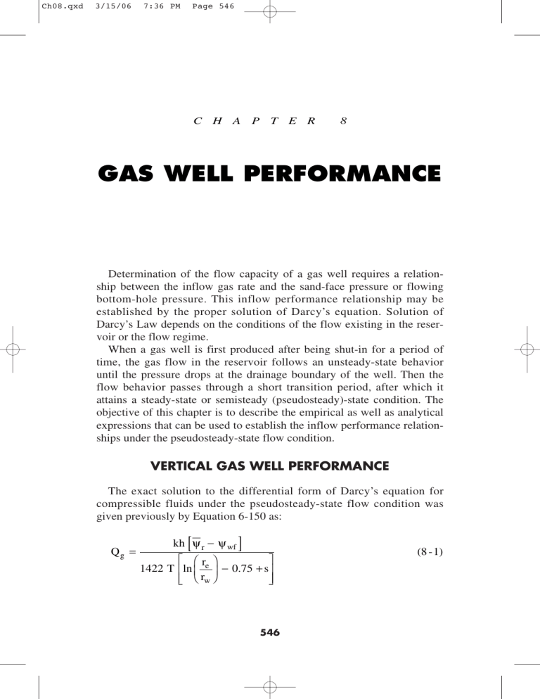
Ch08.qxd 3/15/06 7:36 PM Page 546 C H A P T E R 8 GAS WELL PERFORMANCE Determination of the flow capacity of a gas well requires a relationship between the inflow gas rate and the sand-face pressure or flowing bottom-hole pressure. This inflow performance relationship may be established by the proper solution of Darcy’s equation. Solution of Darcy’s Law depends on the conditions of the flow existing in the reservoir or the flow regime. When a gas well is first produced after being shut-in for a period of time, the gas flow in the reservoir follows an unsteady-state behavior until the pressure drops at the drainage boundary of the well. Then the flow behavior passes through a short transition period, after which it attains a steady-state or semisteady (pseudosteady)-state condition. The objective of this chapter is to describe the empirical as well as analytical expressions that can be used to establish the inflow performance relationships under the pseudosteady-state flow condition. VERTICAL GAS WELL PERFORMANCE The exact solution to the differential form of Darcy’s equation for compressible fluids under the pseudosteady-state flow condition was given previously by Equation 6-150 as: Qg = [ kh ψ r − ψ wf ] ⎡ ⎛r ⎞ ⎤ 1422 T ⎢ln ⎜ e ⎟ − 0.75 + s⎥ ⎢⎣ ⎝ rw ⎠ ⎥⎦ 546 (8 -1) Ch08.qxd 3/15/06 7:36 PM Page 547 Gas Well Performance 547 where Qg = gas flow rate, Mscf/day k = permeability, md – = average reservoir real gas pseudo-pressure, psi2/cp ψ r T = temperature, °R s = skin factor h = thickness re = drainage radius rw = wellbore radius The productivity index J for a gas well can be written analogous to that for oil wells as: J= Qg ψ r − ψ wf = kh ⎡ ⎛r ⎞ ⎤ 1422 T ⎢ln ⎜ e ⎟ − 0.75 + s⎥ ⎥⎦ ⎢⎣ ⎝ rw ⎠ (8 - 2) or Q g = J ( ψ r − ψ wf ) (8 - 3) with the absolute open flow potential (AOF), i.e., maximum gas flow rate (Qg)max, as calculated by: (Q g ) max = J ψ r (8 - 4) where J = productivity index, Mscf/day/psi2/cp (Qg)max= AOF Equation 8-3 can be expressed in a linear relationship as: 1 ψ wf = ψ r − ⎛ ⎞ Q g ⎝ J⎠ (8 - 5) Equation 8-5 indicates that a plot of ψwf vs. Qg would produce a – , as shown in Figure straight line with a slope of (1/J) and intercept of ψ r 8-1. If two different stabilized flow rates are available, the line can be –. extrapolated and the slope is determined to estimate AOF, J, and ψ r Ch08.qxd 3/15/06 7:36 PM Page 548 548 Reservoir Engineering Handbook Figure 8-1. Steady-state gas well flow. Equation 8-1 can be alternatively written in the following integral form: kh Qg = ⎡ ⎛r ⎞ ⎤ 1422 T ⎢ln ⎜ e ⎟ − 0.75 + s⎥ ⎢⎣ ⎝ rw ⎠ ⎥⎦ pr ∫ p wf ⎛ 2p ⎞ ⎜ µ z ⎟ dp ⎝ g ⎠ (8 - 6) Note that (p/µg z) is directly proportional to (1/µg Bg) where Bg is the gas formation volume factor and defined as: Bg = 0.00504 zT p where Bg = gas formation volume factor, bbl/scf z = gas compressibility factor T = temperature, °R (8 - 7) Ch08.qxd 3/15/06 7:36 PM Page 549 Gas Well Performance 549 Equation 8-6 can then be written in terms of Bg as: ⎤ ⎡ ⎥ ⎢ −6 7.08 (10 ) kh ⎥ Qg = ⎢ ⎥ ⎢ ⎛r ⎞ ⎢ ln ⎜ e ⎟ − 0.75 + s ⎥ ⎥⎦ ⎢⎣ ⎝ rw ⎠ pr ∫ p wf ⎛ 1 ⎞ ⎜ µ B ⎟ dp ⎝ g g⎠ (8 - 8) where Qg = gas flow rate, Mscf/day µg = gas viscosity, cp k = permeability, md Figure 8-2 shows a typical plot of the gas pressure functions (2p/µgz) and (1/µg Bg ) versus pressure. The integral in Equations 8-6 and 8-8 represents the area under the curve between –pr and pwf. As illustrated in Figure 8-2, the pressure function exhibits the following three distinct pressure application regions: Region III. High-Pressure Region When both pwf and –pr are higher than 3000 psi, the pressure functions (2p/µgz) and (1/µg Bg ) are nearly constants. This observation suggests that the pressure term (1/µg Bg ) in Equation 8-8 can be treated as a constant and removed outside the integral, to give the following approximation to Equation 8-6: Qg = 7.08 (10 −6 ) kh ( p r − p wf ) ⎡ ⎛r ⎞ ⎤ ( µ g Bg )avg ⎢ln ⎜ e ⎟ − 0.75 + s⎥ ⎢⎣ ⎝ rw ⎠ ⎥⎦ (8 - 9) where Qg = gas flow rate , Mscf/day Bg = gas formation volume factor, bbl/scf k = permeability, md The gas viscosity µg and formation volume factor Bg should be evaluated at the average pressure pavg as given by: p avg = p r + p wf 2 (8 -10) Ch08.qxd 3/15/06 550 7:36 PM Page 550 Reservoir Engineering Handbook Figure 8-2. Gas PVT data. The method of determining the gas flow rate by using Equation 8-9 commonly called the pressure-approximation method. It should be pointed out the concept of the productivity index J cannot be introduced into Equation 8-9 since Equation 8-9 is only valid for applications when both pwf and –pr are above 3000 psi. Region II. Intermediate-Pressure Region Between 2000 and 3000 psi, the pressure function shows distinct curvature. When the bottom-hole flowing pressure and average reservoir pressure are both between 2000 and 3000 psi, the pseudopressure gas pressure approach (i.e., Equation 8-1) should be used to calculate the gas flow rate. Region I. Low-Pressure Region At low pressures, usually less than 2000 psi, the pressure functions (2p/µgz) and (1/µg Bg) exhibit a linear relationship with pressure. Golan and Whitson (1986) indicated that the product (µgz) is essentially constant when evaluating any pressure below 2000 psi. Implementing this observation in Equation 8-6 and integrating gives: Ch08.qxd 3/15/06 7:36 PM Page 551 Gas Well Performance Qg = kh ( p r2 − p 2wf ) ⎡ ⎛r ⎞ ⎤ 1422 T (µ g z)avg ⎢ln ⎜ e ⎟ − 0.75 + s⎥ ⎢⎣ ⎝ rw ⎠ ⎥⎦ 551 (8 -11) where Qg = gas flow rate, Mscf/day k = permeability, md T = temperature, °R z = gas compressibility factor µg = gas viscosity, cp It is recommended that the z-factor and gas viscosity be evaluated at the average pressure pavg as defined by: 2 p avg = p r + p 2wf 2 The method of calculating the gas flow rate by Equation 8-11 is called the pressure-squared approximation method. If both –pr and pwf are lower than 2000 psi, Equation 8-11 can be expressed in terms of the productivity index J as: Q g = J ( p r2 − p 2wf ) (8 -12) with 2 (Q g ) max = AOF = J p r (8 -13) where J= 1422 T (µ g z)avg kh ⎡ ⎛ re ⎞ ⎢ln ⎜ ⎟ − 0.75 + ⎢⎣ ⎝ rw ⎠ ⎤ s⎥ ⎥⎦ (8 -14) Example 8-1 The PVT properties of a gas sample taken from a dry gas reservoir are given in the following table: Ch08.qxd 3/15/06 7:36 PM Page 552 552 Reservoir Engineering Handbook p, psi µg, cp Z ψ, psi2/cp Bg , bbl/scf 0 400 1200 1600 2000 3200 3600 4000 0.01270 0.01286 0.01530 0.01680 0.01840 0.02340 0.02500 0.02660 1.000 0.937 0.832 0.794 0.770 0.797 0.827 0.860 0 13.2 × 10⁶ 113.1 × 10⁶ 198.0 × 10⁶ 304.0 × 10⁶ 678.0 × 10⁶ 816.0 × 10⁶ 950.0 × 10⁶ — 0.007080 0.00210 0.00150 0.00116 0.00075 0.000695 0.000650 The reservoir is producing under the pseudosteady-state condition. The following additional data are available: k = 65 md re = 1000′ h = 15′ rw = 0.25′ T = 600°R s = 0.4 Calculate the gas flow rate under the following conditions: a. –pr = 4000 psi, pwf = 3200 psi b. –pr = 2000 psi, pwf = 1200 psi Use the appropriate approximation methods and compare results with the exact solution. Solution a. Calculate Qg at –pr = 4000 and pwf = 3200 psi: Step 1. Select the approximation method. Because –pr and pwf are both > 3000, the pressure-approximation method is used, i.e., Equation 8-9. Step 2. Calculate average pressure and determine the corresponding gas properties. p= 4000 + 3200 = 3600 psi 2 µg = 0.025 Bg = 0.000695 Ch08.qxd 3/15/06 7:36 PM Page 553 Gas Well Performance 553 Step 3. Calculate the gas flow rate by applying Equation 8-9. 7.08 (10 −6 ) (65) (15)( 4000 − 3200) ⎡ 1000 ⎞ ⎤ − 0.75 − 0.4⎥ (0.025) (0.000695) ⎢ln ⎛ ⎝ ⎠ 0 . 25 ⎣ ⎦ = 44, 490 Mscf / day Qg = Step 4. Recalculate Qg by using the pseudopressure equation, i.e., Equation 8-1. Qg = (65) (15) (950.0 − 678.0) (65) (15)10 6 = 43, 509 Mscf / day ⎡ 1000 ⎞ ⎤ (1422) (600) ⎢ln ⎛ − 0.75 − 0.4⎥ ⎣ ⎝ 0.25 ⎠ ⎦ b. Calculate Qg at –pr = 2000 and pwf = 1058: Step 1. Select the appropriate approximation method. Because –pr and pwf ≤ 2000, use the pressure-squared approximation. Step 2. Calculate average pressure and the corresponding µg and z. p= 2000 2 + 1200 2 = 1649 psi 2 µg = 0.017 z = 0.791 Step 3. Calculate Qg by using the pressure-squared equation, i.e., Equation 8-11. (65) (15) (2000 2 − 1200 2 ) ⎡ 1000 ⎞ ⎤ 1422 (600) (0.017) (0.791) ⎢ln ⎛ − 0.75 − 0.4⎥ ⎝ ⎠ 0.25 ⎣ ⎦ = 30, 453 Mscf / day Qg = Ch08.qxd 3/15/06 7:36 PM 554 Page 554 Reservoir Engineering Handbook Step 4. Compare Qg with the exact value from Equation 8-1: (65) (15) (304.0 − 113.1) 10 6 ⎡ 1000 ⎞ ⎤ (1422) (600) ⎢ln ⎛ − 0.75 − 0.4⎥ ⎝ ⎠ 0.25 ⎣ ⎦ = 30, 536 Mscf / day Qg = All of the mathematical formulations presented thus far in this chapter are based on the assumption that laminar (viscous) flow conditions are observed during the gas flow. During radial flow, the flow velocity increases as the wellbore is approached. This increase of the gas velocity might cause the development of a turbulent flow around the wellbore. If turbulent flow does exist, it causes an additional pressure drop similar to that caused by the mechanical skin effect. As presented in Chapter 6 by Equations 6-164 through 6-166, the semisteady-state flow equation for compressible fluids can be modified to account for the additional pressure drop due the turbulent flow by including the rate-dependent skin factor DQ g. The resulting pseudosteady-state equations are given in the following three forms: First Form: Pressure-Squared Approximation Form ( 2 kh p r − p 2 wf Qg = 1422 T (µ g z)avg ) ⎡ ⎛ re ⎞ ⎤ ⎢ln ⎜ ⎟ − 0.75 + s + DQ g ⎥ ⎢⎣ ⎝ rw ⎠ ⎥⎦ (8 -15) where D is the inertial or turbulent flow factor and is given by Equation 6-160 as: D= FKh 1422 T (8 -16) where the non-Darcy flow coefficient F is defined by Equation 6-156 as: ⎡ βTγ g ⎤ F = 3.161 (10 −12 ) ⎢ ⎥ 2 ⎢⎣ µ g h rw ⎥⎦ (8 -17) Ch08.qxd 3/15/06 7:36 PM Page 555 555 Gas Well Performance where F = non-Darcy flow coefficient k = permeability, md T = temperature, °R γg = gas gravity rw = wellbore radius, ft h = thickness, ft β = turbulence parameter as given by Equation 6-157 as β = 1.88 (10−10) k−1.47 φ−0.53 Second Form: Pressure-Approximation Form Qg = 7.08 (10 −6 ) kh ( p r − p wf ) ⎤ ⎡ ⎛r ⎞ (µ g β g )avg T ⎢ln⎜ e ⎟ − 0.75 + s + DQ g ⎥ ⎢⎣ ⎝ rw ⎠ ⎥⎦ (8 -18) Third Form: Real Gas Potential (Pseudopressure) Form Qg = kh ( ψ r − ψ wf ) ⎡ ⎛r ⎞ ⎤ 1422 T ⎢ln ⎜ e ⎟ − 0.75 + s + DQ g ⎥ ⎢⎣ ⎝ rw ⎠ ⎥⎦ (8 -19) Equations 8-15, 8-18, and 8-19 are essentially quadratic relationships in Qg and, thus, they do not represent explicit expressions for calculating the gas flow rate. There are two separate empirical treatments that can be used to represent the turbulent flow problem in gas wells. Both treatments, with varying degrees of approximation, are directly derived and formulated from the three forms of the pseudosteady-state equations, i.e., Equations 8-15 through 8-17. These two treatments are called: • Simplified treatment approach • Laminar-inertial-turbulent (LIT) treatment The above two empirical treatments of the gas flow equation are presented on the following pages. Ch08.qxd 3/15/06 7:36 PM Page 556 556 Reservoir Engineering Handbook The Simplified Treatment Approach Based on the analysis for flow data obtained from a large member of gas wells, Rawlins and Schellhardt (1936) postulated that the relationship between the gas flow rate and pressure can be expressed as: Q g = C ( p r2 − p 2wf ) n (8 - 20) where Qg = gas flow rate, Mscf/day –p = average reservoir pressure, psi r n = exponent C = performance coefficient, Mscf/day/psi2 The exponent n is intended to account for the additional pressure drop caused by the high-velocity gas flow, i.e., turbulence. Depending on the flowing conditions, the exponent n may vary from 1.0 for completely laminar flow to 0.5 for fully turbulent flow. The performance coefficient C in Equation 8-20 is included to account for: • Reservoir rock properties • Fluid properties • Reservoir flow geometry Equation 8-20 is commonly called the deliverability or back-pressure equation. If the coefficients of the equation (i.e., n and C) can be determined, the gas flow rate Qg at any bottom-hole flow pressure pwf can be calculated and the IPR curve constructed. Taking the logarithm of both sides of Equation 8-20 gives: – 2 − p2 ) log (Qg) = log (C) + n log (p wf r (8 - 21) –2 − p2 ) on log-log Equation 8-22 suggests that a plot of Qg versus (p wf r scales should yield a straight line having a slope of n. In the natural gas –2 − p2 ) versus Q industry the plot is traditionally reversed by plotting (p wf r g on the logarithmic scales to produce a straight line with a slope of (1/n). This plot as shown schematically in Figure 8-3 is commonly referred to as the deliverability graph or the back-pressure plot. Ch08.qxd 3/15/06 7:36 PM Page 557 Gas Well Performance 557 Figure 8-3. Well deliverability graph. The deliverability exponent n can be determined from any two points on the straight line, i.e., (Qg1, ∆p12 ) and (Qg2, ∆p22 ), according to the flowing expression: n= log(Q g1 ) − log(Q g2 ) log( ∆p12 ) − log ( ∆p 22 ) (8 - 22) Given n, any point on the straight line can be used to compute the performance coefficient C from: C= Qg ( p r2 − p 2wf ) n (8 - 23) The coefficients of the back-pressure equation or any of the other empirical equations are traditionally determined from analyzing gas well testing data. Deliverability testing has been used for more than sixty years by the petroleum industry to characterize and determine the flow potential of gas wells. There are essentially three types of deliverability tests and these are: Ch08.qxd 3/15/06 7:36 PM Page 558 558 Reservoir Engineering Handbook • Conventional deliverability (back-pressure) test • Isochronal test • Modified isochronal test These tests basically consist of flowing wells at multiple rates and measuring the bottom-hole flowing pressure as a function of time. When the recorded data are properly analyzed, it is possible to determine the flow potential and establish the inflow performance relationships of the gas well. The deliverability test is discussed later in this chapter for the purpose of introducing basic techniques used in analyzing the test data. The Laminar-Inertial-Turbulent (LIT) Approach The three forms of the semisteady-state equation as presented by Equations 8-15, 8-18, and 8-19 can be rearranged in quadratic forms for the purpose of separating the laminar and inertial-turbulent terms composing these equations as follows: a. Pressure-Squared Quadratic Form Equation 8-15 can be written in a more simplified form as: p r2 − p 2wf = a Q g + b Q 2g (8 - 24) with ⎛ 1422 T µ g z ⎞ a=⎜ ⎟ ⎝ ⎠ kh ⎡ ⎢ln ⎢⎣ ⎛ re ⎞ ⎜ ⎟ − 0.75 + ⎝ rw ⎠ ⎤ s⎥ ⎥⎦ ⎛ 1422 T µ g z ⎞ b=⎜ ⎟ D ⎝ ⎠ kh where a = laminar flow coefficient b = inertial-turbulent flow coefficient Qg = gas flow rate, Mscf/day z = gas deviation factor k = permeability, md µg = gas viscosity, cp (8 - 25) (8 - 26) Ch08.qxd 3/15/06 7:36 PM Page 559 Gas Well Performance 559 The term (a Qg) in Equation 8-26 represents the pressure-squared drop due to laminar flow while the term (b Q2g) accounts for the pressuresquared drop due to inertial-turbulent flow effects. Equation 8-24 can be linearized by dividing both sides of the equation by Qg to yield: p r2 − p 2wf = a + b Qg Qg (8 - 27) ⎛ p r2 − p 2wf ⎞ ⎜ ⎟ The coefficients a and b can be determined by plotting ⎝ Q g ⎠ versus Qg on a Cartesian scale and should yield a straight line with a slope of b and intercept of a. As presented later in this chapter, data from deliverability tests can be used to construct the linear relationship as shown schematically in Figure 8-4. Given the values of a and b, the quadratic flow equation, i.e., Equation 8-24, can be solved for Qg at any pwf from: Qg = ( 2 − a + a 2 + 4 b p r − p 2wf 2b ) (8 - 28) Furthermore, by assuming various values of pwf and calculating the corresponding Qg from Equation 8-28, the current IPR of the gas well at the current reservoir pressure –pr can be generated. It should be pointed out the following assumptions were made in developing Equation 8-24: • Single phase flow in the reservoir • Homogeneous and isotropic reservoir system • Permeability is independent of pressure • The product of the gas viscosity and compressibility factor, i.e., (µg z) is constant. This method is recommended for applications at pressures below 2000 psi. Ch08.qxd 3/15/06 7:36 PM 560 Page 560 Reservoir Engineering Handbook Figure 8-4. Graph of the pressure-squared data. b. Pressure-Quadratic Form The pressure-approximation equation, i.e., Equation 8-18, can be rearranged and expressed in the following quadratic form. p r − p wf = a1 Q g + b1 Q 2g (8 - 29) where a1 = ⎤ 141.2 (10 −3 ) (µ g Bg ) ⎡ ⎛ re ⎞ ⎢ln ⎜ ⎟ − 0.75 + s⎥ kh ⎥⎦ ⎢⎣ ⎝ rw ⎠ ⎡ 141.2 (10 −3 ) (µ g Bg ) ⎤ b1 = ⎢ ⎥D kh ⎢⎣ ⎥⎦ (8 - 30) (8 - 31) The term (a1 Qg) represents the pressure drop due to laminar flow, while the term (b1 Q2g) accounts for the additional pressure drop due to Ch08.qxd 3/15/06 7:36 PM Page 561 Gas Well Performance 561 the turbulent flow condition. In a linear form, Equation 8-17 can be expressed as: p r − p wf = a1 + b1 Q g Qg (8 - 32) The laminar flow coefficient a1 and inertial-turbulent flow coefficient b1 can be determined from the linear plot of the above equation as shown in Figure 8-5. Having determined the coefficient a1 and b1, the gas flow rate can be determined at any pressure from: Qg = − a1 + a 21 + 4 b1 ( p r − p wf ) 2 b1 (8 - 33) The application of Equation 8-29 is also restricted by the assumptions listed for the pressure-squared approach. However, the pressure method is applicable at pressures higher than 3000 psi. Figure 8-5. Graph of the pressure-method data. Ch08.qxd 3/15/06 7:36 PM 562 Page 562 Reservoir Engineering Handbook c. Pseudopressure Quadratic Approach Equation 8-19 can be written as: ψ r − ψ wf = a 2 Q g + b 2 Q 2g (8 - 34) where 1422 ⎞ ⎡ ⎛ re ⎞ ln − 0.75 + a2 = ⎛ ⎝ kh ⎠ ⎢⎢ ⎜⎝ rw ⎟⎠ ⎣ ⎤ s⎥ ⎥⎦ 1422 ⎞ b2 = ⎛ D ⎝ kh ⎠ (8 - 35) (8 - 36) The term (a2 Qg) in Equation 8-34 represents the pseudopressure drop due to laminar flow while the term (b2 Qg2 ) accounts for the pseudopressure drop due to inertial-turbulent flow effects. Equation 8-34 can be linearized by dividing both sides of the equation by Qg to yield: ψ r − ψ wf a 2 + b2 Qg Qg (8 - 37) ⎛ ψ r − ψ wf ⎞ ⎜ ⎟ Qg The above expression suggests that a plot of ⎝ ⎠ versus Qg on a Cartesian scale should yield a straight line with a slope of b2 and intercept of a2 as shown in Figure 8-6. Given the values of a2 and b2, the gas flow rate at any pwf is calculated from: Qg = −a 2 + a 22 + 4 b 2 ( ψ r − ψ wf ) 2 b2 (8 - 38) It should be pointed out that the pseudopressure approach is more rigorous than either the pressure-squared or pressure-approximation method and is applicable to all ranges of pressure. Ch08.qxd 3/15/06 7:36 PM Page 563 Gas Well Performance 563 Figure 8-6. Graph of real gas pseudo-pressure data. In the next section, the back-pressure test is introduced. The material, however, is intended only to be an introduction. There are several excellent books by the following authors that address transient flow and well testing in great detail: • Earlougher (1977) • Matthews and Russell (1967) • Lee (1982) • Canadian Energy Resources Conservation Board (1975). The Back-Pressure Test Rawlins and Schellhardt (1936) proposed a method for testing gas wells by gauging the ability of the well to flow against various back pressures. This type of flow test is commonly referred to as the conventional deliverability test. The required procedure for conducting this back-pressure test consists of the following steps: Ch08.qxd 3/15/06 564 7:36 PM Page 564 Reservoir Engineering Handbook Step 1. Shut in the gas well sufficiently long for the formation pressure to equalize at the volumetric average pressure –pr. Step 2. Place the well on production at a constant flow rate Qg1 for a sufficient time to allow the bottom-hole flowing pressure to stabilize at pwf1, i.e., to reach the pseudosteady state. Step 3. Repeat Step 2 for several rates and the stabilized bottom-hole flow pressure is recorded at each corresponding flow rate. If three or four rates are used, the test may be referred to as a three-point or four-point flow test. The rate and pressure history of a typical four-point test is shown in Figure 8-7. The figure illustrates a normal sequence of rate changes where the rate is increased during the test. Tests may be also run, however, using a reverse sequence. Experience indicates that a normal rate sequence gives better data in most wells. The most important factor to be considered in performing the conventional deliverability test is the length of the flow periods. It is required that each rate be maintained sufficiently long for the well to stabilize, i.e., to reach the pseudosteady state. The stabilization time for a well in the center of a circular or square drainage area may be estimated from: Figure 8-7. Conventional back-pressure test. Ch08.qxd 3/15/06 7:36 PM Page 565 565 Gas Well Performance ts = 1200 φ Sg µ g re2 where ts φ µg Sg k –p r re (8 - 39) k pr = stabilization time, hr = porosity, fraction = gas viscosity, cp = gas saturation, fraction = gas effective permeability, md = average reservoir pressure, psia = drainage radius, ft The application of the back-pressure test data to determine the coefficients of any of the empirical flow equations is illustrated in the following example. Example 8-2 A gas well was tested using a three-point conventional deliverability test. Data recorded during the test are given below: pwf, psia ψwf, psi2/cp Qg, Mscf/day –p = 1952 r 1700 1500 1300 316 × 106 245 × 106 191 × 106 141 × 106 0 2624.6 4154.7 5425.1 Figure 8-8 shows the gas pseudopressure ψ as a function of pressure. Generate the current IPR by using the following methods. a. Simplified back-pressure equation b. Laminar-inertial-turbulent (LIT) methods: i. Pressure-squared approach, Equation 8-29 ii. Pressure-approach, Equation 8-33 iii. Pseudopressure approach, Equation 8-26 c. Compare results of the calculation. 3/15/06 7:36 PM Page 566 566 Reservoir Engineering Handbook 3.50E+08 3.00E+08 2.50E+08 Real Gas Potential Ch08.qxd 2.00E+08 1.50E+08 1.00E+08 5.00E+07 0.00E+00 0 500 1000 1500 2000 2500 Pressure Figure 8-8. Real gas potential vs. pressure. Solution a. Back-Pressure Equation: Step 1. Prepare the following table: pwf –p = 1952 r 1700 1500 1300 p2wf, psi2 × 103 – 2 − p2 ), psi2 × 103 (p wf r Qg, Mscf/day 3810 2890 2250 1690 0 920 1560 2120 0 2624.6 4154.7 5425.1 – 2 − p2 ) versus Q on a log-log scale as shown in Figure Step 2. Plot (p wf r g 8-9. Draw the best straight line through the points. Step 3. Using any two points on the straight line, calculate the exponent n from Equation 8-22, as n= log(4000) − log(1800) = 0.87 log(1500) − log(600) Ch08.qxd 3/15/06 7:36 PM Page 567 Gas Well Performance 567 Figure 8-9. Back-pressure curve. Step 4. Determine the performance coefficient C from Equation 8-23 by using the coordinate of any point on the straight line, or: C= 1800 = 0.0169 Mscf / psi 2 (600, 000)0.87 Step 5. The back-pressure equation is then expressed as: Qg = 0.0169 (3,810,000 − p2wf)0.87 Step 6. Generate the IPR data by assuming various values of pwf and calculate the corresponding Qg. pwf Qg, Mscf/day 1952 1800 1600 1000 500 0 0 1720 3406 6891 8465 8980 = AOF = (Qg)max 3/15/06 7:36 PM Page 568 568 Reservoir Engineering Handbook b. LIT Method i. Pressure-squared method Step 1. Construct the following table: pwf – 2 − p2 ), psi2 × 103 (p wf r Qg, Mscf/day – 2 − p2 )/Q (p wf r g –p = 1952 r 1700 1500 1300 0 920 1560 2120 0 2624.6 4154.7 5425.1 — 351 375 391 – 2 − p2 )/Q versus Q on a Cartesian scale and draw the Step 2. Plot (p wf r g g best straight line as shown in Figure 8-10. Step 3. Determine the intercept and the slope of the straight line to give: a = 318 b = 0.01333 intercept slope Step 4. The quadratic form of the pressure-squared approach can be expressed as: (3,810,000 − p2wf) = 318 Qg + 0.01333 Q2g 400.00 Differential Pressure Over Flow Rate Ch08.qxd 380.00 360.00 340.00 320.00 300.00 0 1000 2000 3000 4000 Flow Rate Figure 8-10. Pressure-squared method. 5000 6000 Ch08.qxd 3/15/06 7:36 PM Page 569 569 Gas Well Performance Step 5. Construct the IPR data by assuming various values of pwf and solving for Qg by using Equation 8-28. pwf – 2 − p2 ), psi2 × 103 (p wf r Qg, Mscf/day –p = 1952 r 1800 1600 1000 500 0 0 570 1250 2810 3560 3810 0 1675 3436 6862 8304 8763 = AOF = (Qg)max ii. Pressure-approximation method Step 1. Construct the following table: Pwf –p = 1952 r 1700 1500 1300 – −p ) (p r wf 0 252 452 652 Qg, Mscf/day 0 262.6 4154.7 5425.1 – − p )/Q (p r wf g — 0.090 0.109 0.120 – − p )/Q versus Q on a Cartesian scale as shown in Step 2. Plot (p r wf g g Figure 8-11. Draw the best straight line and determine the intercept and slope as: intercept a1 = 0.06 slope b1 = 1.111 × 10⁻⁵ Step 3. The quadratic form of the pressure-approximation method is then given by: (1952 − pwf) = 0.06 Qg + 1.111 (10−5) Q2g Step 4. Generate the IPR data by applying Equation 8-33: pwf – −p ) (p r wf Qg, Mscf/day 1952 1800 1600 1000 500 0 0 152 352 952 1452 1952 0 1879 3543 6942 9046 10827 3/15/06 7:36 PM Page 570 570 Reservoir Engineering Handbook 0.14 0.12 Differential Pr essure O ver FlowRate Ch08.qxd 0.10 0.08 0.06 0.04 0.02 0.00 0 1000 2000 3000 4000 5000 6000 Flow Rate Figure 8-11. Pressure-approximation method. iii. Pseudopressure approach Step 1. Construct the following table: pwf ψ, psi2/cp – −ψ ) (ψ r wf Qg, Mscf/day – − ψ )/Q (ψ r wf g –p = 1952 r 1700 1500 1300 316 × 106 245 × 106 191 × 106 141 × 106 0 71 × 106 125 × 106 175 × 106 0 262.6 4154.7 5425.1 — 27.05 × 10³ 30.09 × 10³ 32.26 × 10³ – − ψ )/Q on a Cartesian scale as shown in Figure 8-12 Step 2. Plot (ψ r wf g and determine the intercept a2 and slope b2, or: a2 = 22.28 × 10³ b2 = 1.727 Step 3. The quadratic form of the gas pseudopressure method is given by: (316 × 106 − ψwf) = 22.28 × 10³ Qg + 1.727 Q2g Step 4. Generate the IPR data by assuming various values of pwf, i.e., ψwf, and calculate the corresponding Qg from Equation 8-38. 3/15/06 7:36 PM Page 571 571 Gas Well Performance 33000 32000 Differential Pressure Over Flow Rate Ch08.qxd 31000 30000 29000 28000 27000 26000 0 1000 2000 3000 4000 5000 6000 Flow Rate Figure 8-12. Pseudopressure method. pwf ψ – −ψ ψ r wf Qg, Mscf/day 1952 1800 1600 1000 500 0 316 × 106 270 × 106 215 × 106 100 × 106 40 × 106 0 0 46 × 106 101 × 106 216 × 106 276 × 106 316 × 106 0 1794 3503 6331 7574 8342 = AOF (Qg)max c. Compare the gas flow rates as calculated by the four different methods. Results of the IPR calculation are documented below: Gas Flow Rate, Mscf/day Pressure Back-pressure p2-Approach p-Approach ψ-Approach 19520 1800 1600 1000 500 0 0 1720 3406 6891 8465 8980 6.0% 0 1675 3436 6862 8304 8763 5.4% 0 1879 3543 6942 9046 10827 11% 0 1811 3554 6460 7742 8536 — 3/15/06 7:36 PM 572 Page 572 Reservoir Engineering Handbook Since the pseudo-pressure analysis is considered more accurate and rigorous than the other three methods, the accuracy of each of the methods in predicting the IPR data is compared with that of the ψ-approach. Figure 8-13 compares graphically the performance of each method with that of ψ-approach. Results indicate that the pressure-squared equation generated the IPR data with an absolute average error of 5.4% as compared with 6% and 11% for the back-pressure equation and the pressureapproximation method, respectively. It should be noted that the pressure-approximation method is limited to applications for pressures greater than 3000 psi. Future Inflow Performance Relationships Once a well has been tested and the appropriate deliverability or inflow performance equation established, it is essential to predict the IPR data as a function of average reservoir pressure. The gas viscosity µg and gas compressibility z-factor are considered the parameters that are subject to the greatest change as reservoir pressure –pr changes. Assume that the current average reservoir pressure is –pr, with gas viscosity of µg and a compressibility factor of z1. At a selected future average reservoir pressure –pr2, µg2 and z2 represent the corresponding gas properties. To approximate the effect of reservoir pressure changes, i.e. from –pr1 2500 2000 Pressure (psi) Ch08.qxd Qg (Back-pressure) Qg (Pressure-Squared) Qg (Pressure) Qg (Psuedopressure) 1500 1000 500 0 0 2000 4000 6000 8000 Flow Rate (Mscf/day) Figure 8-13. IPR for all methods. 10000 12000 Ch08.qxd 3/15/06 7:36 PM Page 573 Gas Well Performance 573 to –pr2, on the coefficients of the deliverability equation, the following methodology is recommended: Back-Pressure Equation The performance coefficient C is considered a pressure-dependent parameter and adjusted with each change of the reservoir pressure according to the following expression: ⎡ µ g1 z1 ⎤ C 2 = C1 ⎢ ⎥ ⎢⎣ µ g2 z 2 ⎥⎦ (8 - 40) The value of n is considered essentially constant. LIT Methods The laminar flow coefficient a and the inertial-turbulent flow coefficient b of any of the previous LIT methods, i.e., Equations 8-24, 8-29, and 8-34, are modified according to the following simple relationships: • Pressure-Squared Method The coefficients a and b of pressure-squared are modified to account for the change of the reservoir pressure from –pr1 to –pr2 by adjusting the coefficients as follows: ⎡ µ g2 z 2 ⎤ a 2 = a1 ⎢ ⎥ ⎢⎣ µ g1 z1 ⎥⎦ (8 - 41) ⎡ µ g2 z 2 ⎤ b 2 = b1 ⎢ ⎥ ⎢⎣ µ g1 z1 ⎥⎦ (8 - 42) where the subscripts 1 and 2 represent conditions at reservoir pressure –p to –p , respectively. r1 r2 • Pressure-Approximation Method ⎡ µ g2 β g2 ⎤ a 2 = a1 ⎢ ⎥ ⎢⎣ µ g1 β g1 ⎥⎦ (8 - 43) Ch08.qxd 3/15/06 7:36 PM Page 574 574 Reservoir Engineering Handbook ⎡ µ g2 β g2 ⎤ b 2 = b1 ⎢ ⎥ ⎢⎣ µ g1 β g1 ⎥⎦ (8 - 44) where Bg is the gas formation volume factor. • Pseudopressure Approach The coefficients a and b of the pseudo-pressure approach are essentially independent of the reservoir pressure and they can be treated as constants. Example 8-3 In addition to the data given in Example 8-2, the following information is available: • (µg z) = 0.01206 at 1952 psi • (µg z) = 0.01180 at 1700 psi Using the following methods: a. Back-pressure method b. Pressure-squared method c. Pseudo-pressure method Generate the IPR data for the well when the reservoir pressure drops from 1952 to 1700 psi. Solution Step 1. Adjust the coefficients a and b of each equation. For the: • Back-pressure equation: Using Equation 8-40, adjust C: 0.01206 ⎞ = 0.01727 C = 0.0169 ⎛ ⎝ 0.01180 ⎠ Qg = 0.01727 (17002 − p2wf)0.87 • Pressure-squared method: Adjust a and b by applying Equations 8-41 and 8-42 0.01180 ⎞ = 311.14 a = 318 ⎛ ⎝ 0.01206 ⎠ Ch08.qxd 3/15/06 7:36 PM Page 575 575 Gas Well Performance 0.01180 ⎞ = 0.01304 b = 0.01333 ⎛ ⎝ 0.01206 ⎠ (17002 − p2wf) = 311.14 Qg + 0.01304 Q2g • Pseudopressure method: No adjustments are needed. (245 × 106) − ψwf = (22.28 × 10³) Qg + 1.727 Q2g Step 2. Generate the IPR data: Gas Flow rate Qg, Mscf/day pwf –p = 1700 r 1600 1000 500 0 Back-Pressure p2-Method ψ-Method 0 1092 4987 6669 7216 0 1017 5019 6638 7147 0 1229 4755 6211 7095 Figure 8-14 compares graphically the IPR data as predicted by the above three methods. Mishra and Caudle (1984) pointed out that when multipoint tests cannot be run due to economic or other reasons, single-point test data can be used to generate the IPR provided that a shut-in bottom-hole pressure, also known as average reservoir pressure, is known. The authors suggested the following relationship: Qg (Q g )max ⎡ m ( p2 ) ⎤ ⎞ ⎛ wf ⎢ − 1⎥ ⎜ ⎢ m( p ) ⎥⎟ r ⎣ ⎦ = 1.25 ⎜ 1 − 5 ⎟ ⎜ ⎟ ⎟⎠ ⎝⎜ In terms of the pressure-squared method: Qg (Q g )max ⎡ 2 ⎤⎞ ⎛ ⎢ Pwf −1⎥ ⎜ ⎢ 2 ⎥⎟ p = 1.25 ⎜ 1 − 5⎢⎣ r ⎥⎦ ⎟ ⎟ ⎜ ⎟ ⎜ ⎠ ⎝ Ch08.qxd 3/15/06 7:36 PM 576 Page 576 Reservoir Engineering Handbook Figure 8-14. IPR comparison. And in terms of the pressure-approximation method: Qg (Q g )max ⎡p ⎛ ⎢ wf ⎜ ⎢ p = 1.25 ⎜ 1 − 5⎣ r ⎜ ⎜⎝ ⎤⎞ − 1⎥ ⎥⎟ ⎦ ⎟ ⎟ ⎟⎠ For predicting future IPR, Mishra and Caudle proposed the following expression: ⎡ m( p ) ⎤ ⎞ ⎛ wf f ⎥ ⎢ ⎜ ⎢ m( p ) ⎥ ⎟ (Q max )f 5 r p ⎦ ⎟ = ⎜ 1 − 0.4 ⎣ (Q max ) P 3 ⎜ ⎟ ⎜⎝ ⎟⎠ where the subscripts f and p denote future and present, respectively. Ch08.qxd 3/15/06 7:36 PM Page 577 Gas Well Performance 577 HORIZONTAL GAS WELL PERFORMANCE Many low permeability gas reservoirs are historically considered to be noncommercial due to low production rates. Most vertical wells drilled in tight gas reservoirs are stimulated using hydraulic fracturing and/or acidizing treatments to attain economical flow rates. In addition, to deplete a tight gas reservoir, vertical wells must be drilled at close spacing to efficiently drain the reservoir. This would require a large number of vertical wells. In such reservoirs, horizontal wells provide an attractive alternative to effectively deplete tight gas reservoirs and attain high flow rates. Joshi (1991) points out those horizontal wells are applicable in both low-permeability reservoirs as well as in high-permeability reservoirs. An excellent reference textbook by Sada Joshi (1991) gives a comprehensive treatment of horizontal wells performance in oil and gas reservoirs. In calculating the gas flow rate from a horizontal well, Joshi introduced the concept of the effective wellbore radius r′w into the gas flow equation. The effective wellbore radius is given by: rw′ = reh ( L / 2) a [1 + 1 − ( L / 2a )2 [h / (2 rw )]h / L (8 - 45) with [ L a = ⎛ ⎞ 0.5 + 0.25 + (2 reh / L) 4 ⎝ 2⎠ ] 0.5 (8 - 46) and reh = 43, 560 A π where L = length of the horizontal well, ft h = thickness, ft rw = wellbore radius, ft reh = horizontal well drainage radius, ft a = half the major axis of drainage ellipse, ft A = drainage area, acres (8 - 47) Ch08.qxd 3/15/06 7:36 PM Page 578 578 Reservoir Engineering Handbook Methods of calculating the horizontal well drainage area A are presented in Chapter 7 by Equations 7-45 and 7-46. For a pseudosteady-state flow, Joshi expressed Darcy’s equation of a laminar flow in the following two familiar forms: Pressure-Squared Form Qg = kh ( p r2 − p 2wf ) 1422 T (µ g z)avg [ln( reh / r ′w) − 0.75 + s] (8 - 48) where Qg = gas flow rate, Mscf/day s = skin factor k = permeability, md T = temperature, °R Pseudo-Pressure Form Qg = kh ( ψ r − ψ wf ) ⎤ ⎡ ⎛r ⎞ 1422 T ⎢ln ⎜ eh ⎟ − 0.75 + s⎥ ⎢⎣ ⎝ rw ⎠ ⎥⎦ Example 8-4 A 2,000-foot-long horizontal gas well is draining an area of approximately 120 acres. The following data are available: –p = 2000 psi r pwf = 1200 psi – = 340 × 106 psi2/cp ψ r ψwf = 128 × 106 psi2/cp (µg z)avg = 0.011826 h = 20 ft rw = 0.3 ft T = 180°F s = 0.5 k = 1.5 md Assuming a pseudosteady-state flow, calculate the gas flow rate by using the pressure-squared and pseudopressure methods. Ch08.qxd 3/15/06 7:36 PM Page 579 579 Gas Well Performance Solution Step 1. Calculate the drainage radius of the horizontal well: ( 43, 560) (120) = 1290 ft π reh = Step 2. Calculate half the major axis of drainage ellipse by using Equation 8-46: 2000 ⎤ ⎡ ⎢0.5 + 0.25 + a = ⎡⎢ ⎣ 2 ⎥⎦ ⎢ ⎣ 4⎤ ⎡ (2) (1290) ⎤ ⎥ ⎢⎣ 2000 ⎥⎦ ⎥ ⎦ 0.5 = 1495.8 Step 3. Calculate the effective wellbore radius r′w from Equation 8-45: ⎡ 20 ⎤ ( h / 2 rw ) h / L = ⎢ ⎥ ⎣ (2) (0.3) ⎦ ⎛ L⎞ 1+ 1− ⎜ ⎟ ⎝ 2a⎠ 2 20 / 2000 = 1.0357 2 ⎛ 2000 ⎞ = 1 + 1−⎜ ⎟ = 1.7437 ⎝ 2 (1495.8) ⎠ Applying Equation 8-45, gives: rw′ = 1290 (200 / 2) = 477.54 ft 1495.8 (1.7437) (1.0357) Step 4. Calculate the flow rate by using the pressure-squared approximation and ψ-approach. • Pressure-squared (1.5) (20) (2000 2 − 1200 2 ) 1290 ⎞ ⎡ ⎤ (1422) (640) (0.011826) ⎢ln ⎛ − 0.75 + 0.5⎥ ⎝ ⎠ 477 . 54 ⎣ ⎦ = 9, 594Mscf / day Qg = Ch08.qxd 3/15/06 7:36 PM Page 580 580 Reservoir Engineering Handbook • ψ-Method (1.5) (20) (340 − 128) (10 6 ) 1290 ⎞ ⎡ ⎤ (1422) (640) ⎢ln ⎛ − 0.75 + 0.5⎥ ⎝ ⎠ ⎣ 477.54 ⎦ = 9396 Mscf / day Qg = For turbulent flow, Darcy’s equation must be modified to account for the additional pressure caused by the non-Darcy flow by including the rate-dependent skin factor DQg. In practice, the back-pressure equation and the LIT approach are used to calculate the flow rate and construct the IPR curve for the horizontal well. Multirate tests, i.e., deliverability tests, must be performed on the horizontal well to determine the coefficients of the selected flow equation. PROBLEMS 1. A gas well is producing under a constant bottom-hole flowing pressure of 1000 psi. The specific gravity of the produced gas is 0.65, given: pi = 1500 psi h = 20 ft rw = 0.33 ft T = 140°F re = 1000 ft s = 0.40 k = 20 md Calculate the gas flow rate by using: a. Real gas pseudopressure approach b. Pressure-squared approximation 2. The following data1 were obtained from a back-pressure test on a gas well. 1Chi Qg, Mscf/day pwf, psi 0 4928 6479 8062 9640 481 456 444 430 415 Ikoku, Natural Gas Reservoir Engineering, John Wiley and Sons, 1984. Ch08.qxd 3/15/06 7:36 PM Page 581 581 Gas Well Performance a. Calculate values of C and n b. Determine AOF c. Generate the IPR curves at reservoir pressures of 481 and 300 psi. 3. The following back-pressure test data are available: Qg, Mscf/day pwf, psi 0 1000 1350 2000 2500 5240 4500 4191 3530 2821 Given: gas gravity porosity swi T = 0.78 = 12% = 15% = 281°F a. Generate the current IPR curve by using: i. Simplified back-pressure equation ii. Laminar-inertial-turbulent (LIT) methods: • Pressure-squared approach • Pressure-approximation approach • Pseudopressure approach b. Repeat part a for a future reservoir pressure of 4000 psi. 4. A 3,000-foot horizontal gas well is draining an area of approximately 180 acres, given: pi = 2500 psi T = 120°F υg = 0.65 pwf = 1500 psi rw = 0.25 k = 25 md h = 20 ft Calculate the gas flow rate. REFERENCES 1. Earlougher, Robert C., Jr., Advances in Well Test Analysis. Mongraph Vol. 5, Society of Petroleum Engineers of AIME. Dallas, TX: Millet the Printer, 1977. Ch08.qxd 3/15/06 582 7:36 PM Page 582 Reservoir Engineering Handbook 2. ERCB. Theory and Practice of the Testing of Gas Wells, 3rd ed. Calgary: Energy Resources Conservation Board, 1975. 3. Fetkovich, M. J., “Multipoint Testing of Gas Wells,” SPE Mid-continent Section Continuing Education Course of Well Test Analysis, March 17, 1975. 4. Golan, M., and Whitson, C., Well Performance. International Human Resources Development Corporation, 1986. 5. Joshi, S., Horizontal Well Technology. Tulsa, OK: PennWell Publishing Company, 1991. 6. Lee, J., Well Testing. Dallas: Society of Petroleum Engineers of AIME, 1982. 7. Matthews, C., and Russell, D., “Pressure Buildup and Flow Tests in Wells.” Dallas: SPE Monograph Series, 1967. 8. Rawlins, E. L., and Schellhardt, M. A., “Back-Pressure Data on Natural Gas Wells and Their Application to Production Practices.” U.S. Bureau of Mines Monograph 7, 1936.
