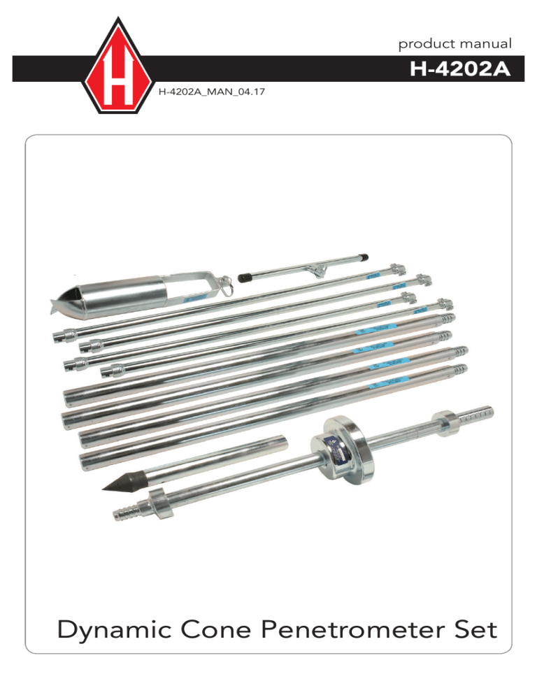
product manual H-4202A H-4202A_MAN_04.17 Dynamic Cone Penetrometer Set BACKGROUND: The Standard Penetration Test (SPT) has its roots in the empirical observation of blows per unit measure of driving casing. The SPT method requires mechanized equipment to raise and drop a 140lb mass 30 in.. Numerous methods have been developed to miniaturize the SPT such that hand operated tools could be used at shallow depths where confined spaces or the need for expedience excludes the use of a mechanized SPT device. The late Prof. George Sowers developed one of the more popular devices in 1959 for field exploration and the evaluation of lightly loaded shallow spread footings during the construction phase. For underlying theory the reader is encouraged to consult the following reference: George F. Sowers and Charles S. Hedges. Dynamic Cone for Shallow In-Situ Penetration Testing, Vane Shear and Cone Penetrations Resistance Testing of In-Situ Soils, ASTM STP 399, American Society Testing and Materials, 1966, pg. 29. The Dynamic Cone Penetrometer (DCP) illustrated in Figure 1a, uses a 15 lb steel mass falling 20 in. to strike an anvil to penetrate a 1.5 in. diameter 45 degree cone that has been seated in the bottom of a hand augered hole. The device has been used extensively in the Southeastern region of the USA and calibrated with standard SPT results. The original correlations by Sowers are shown in Figure 1b. Of course, similar correlation could be developed for soils of other regions and of differing geologic derivation. OPERATING INSTRUCTIONS: 1. The penetration test is performed in the bottom of a hand augered hole generally 3 to 6 in. diameter. 2. Auger to the desired test depth taking care to remove as much of the bottom cuttings as practical. Use the auger cuttings to identify and visually classify the soil. WARNING: Handle the Dynamic Cone Penetrometer with care. Do not grasp the E-rod between the pull out anvil and the driving anvil as the 15 lb. sliding weight moves easily along this part of the rod. 3.Gently lower the sliding drive hammer, extension rods and drive point to the bottom of the borehole. 4. Making sure the assembly is plumb set the cone 2 in. into the undisturbed bottom of the hole such that the cone is completely embedded. NOTE: Laying a flat straight edge such as a survey stake across the borehole and marking a beginning reference point will expedite measurements. 5. Maintaining the assembly in a plumb position, drive the cone point l-3/4 in. (44mm) using the ring weight and allowing it to free fall 20 in. (bringing the ring weight to the uppermost position against the pullout anvil will assure a 20 in. drop). Count and record the number of blows required to achieve l-3/4 in. (44mm) penetration. 6. If desired, perform a second and third penetration test by driving the cone additional 3/4 in. (44mm) increments. Beyond three increments the effect of shaft friction may become apparent. 7. Remove the DCP assembly from the borehole taking care not to place hands between the anvil and keeping clear of the sliding weight. 8. Auger to the next test location and repeat steps) through 7. Experience has shown that the DCP can be effectively used in auger holes to depths of 15 to 20 ft. Beyond these depths it becomes cumbersome to handle the string of rods by hand. Also, correlations have not been verified for deeper depths where energy losses from thread joints and rod inertia have not been considered Drive Tube Accessory The Cone and Adapter Rod Assembly can be replaced with the H-4202.7A Drive Tube Assembly for taking 3 x 10" tube, H-4202.10, samples in augered holes. Dynamic Cone Penetrometer Individual Items Description Model Standard drive hammer H-4202.1 Sleeved drive hammer H-4202.1A E drill rod extension 1 ft. H-4202.21 E drill rod extension 2 ft. H-4202.22 E drill rod extension 2.5 ft. H-4202.225 E drill rod extension 5 ft. H-4202.25 Drive point (45° cone), 1 ft. Rod H-4202.3 Drive point (45° cone), No Rod H-4202.3DP Auger assembly: (Head, (2) pins, T-handle, (1) extension Auger T-handle Auger T-handle, SS Auger extension. 36" Auger extension, SS, 36" Auger head, standard 3.25" H-4202.6A H-4202.4 H-4202.4SS H-4202.5 H-4202.5SS H-4202.6 Auger head, SS, 3.25". H-4202.6SS Windowed auger head, 3.25" (heat-treated carbon steel). H-4202.6W Windowed auger head, standard (stainless steel) 3.25" H-4202.6WSS Shelby Tube Drive Head, 3" E Rod Replacement connector pin. Replacement connector pin, SS H-4202.7A H-4202.8 H-4202.8SS Warranty Humboldt Mfg. Co. warrants its products to be free from defects in material or workmanship. The exclusive remedy for this warranty is Humboldt Mfg. Co., factory replacement of any part or parts of such product, for the warranty of this product please refer to Humboldt Mfg. Co. catalog on Terms and Conditions of Sale. The purchaser is responsible for the transportation charges. Humboldt Mfg. Co. shall not be responsible under this warranty if the goods have been improperly maintained, installed, operated or the goods have been altered or modified so as to adversely affect the operation, use performance or durability or so as to change their intended use. The Humboldt Mfg. Co. liability under the warranty contained in this clause is limited to the repair or replacement of defective goods and making good, defective workmanship. Humboldt Mfg. Co. 3801 North 25th Avenue Schiller Park, Illinois 60176 U.S.A. U.S.A. Toll Free: 1.800.544.7220 Voice: 1.708.456.6300 Fax: 1.708.456.0137 Email: hmc@humboldtmfg.com Testing Equipment for Construction Materials HUMBOLDT www.humboldtmfg.com
