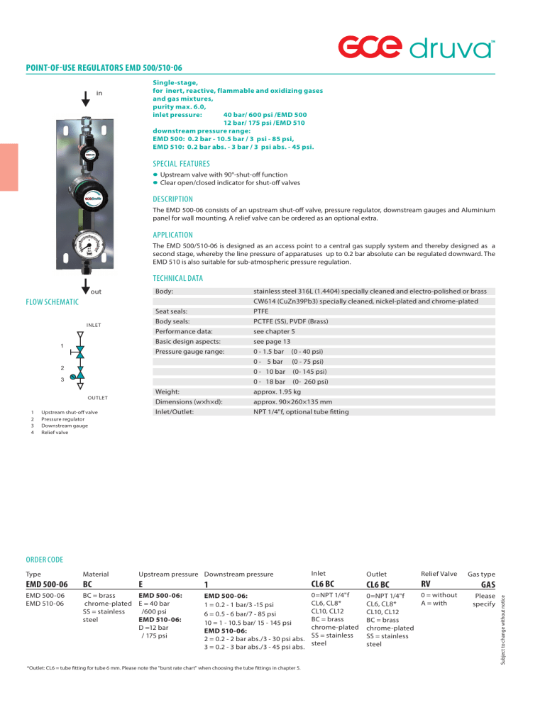
POINT-OF-USE REGULATORS EMD 500/510-06 Single-stage, for inert, reactive, flammable and oxidizing gases and gas mixtures, purity max. 6.0, inlet pressure: 40 bar/ 600 psi /EMD 500 12 bar/ 175 psi /EMD 510 downstream pressure range: EMD 500: 0.2 bar - 10.5 bar / 3 psi - 85 psi, EMD 510: 0.2 bar abs. - 3 bar / 3 psi abs. - 45 psi. in SPECIAL FEATURES valve with 90°-shut-off function • Upstream • Clear open/closed indicator for shut-off valves DESCRIPTION The EMD 500-06 consists of an upstream shut-off valve, pressure regulator, downstream gauges and Aluminium panel for wall mounting. A relief valve can be ordered as an optional extra. APPLICATION The EMD 500/510-06 is designed as an access point to a central gas supply system and thereby designed as a second stage, whereby the line pressure of apparatuses up to 0.2 bar absolute can be regulated downward. The EMD 510 is also suitable for sub-atmospheric pressure regulation. TECHNICAL DATA Body: stainless steel 316L (1.4404) specially cleaned and electro-polished or brass CW614 (CuZn39Pb3) specially cleaned, nickel-plated and chrome-plated Seat seals: PTFE Body seals:PCTFE (SS), PVDF (Brass) Performance data: see chapter 5 Basic design aspects: see page 13 Pressure gauge range: 0 - 1.5 bar (0 - 40 psi) 0 - 5 bar (0 - 75 psi) 0 - 10 bar (0- 145 psi) 0 - 18 bar (0- 260 psi) Weight: approx. 1.95 kg Dimensions (w×h×d):approx. 90×260×135 mm Inlet/Outlet:NPT 1/4"f, optional tube fitting out FLOW SCHEMATIC INLET 1 2 3 OUTLET 1 2 3 4 Upstream shut-off valve Pressure regulator Downstream gauge Relief valve ORDER CODE Material Upstream pressure Downstream pressure EMD 500-06 BC E EMD 500-06 EMD 510-06 BC = brass EMD 500-06: chrome-plated E = 40 bar SS = stainless /600 psi steel EMD 510-06: D =12 bar / 175 psi Inlet 1 CL6 BC EMD 500-06: 1 = 0.2 - 1 bar/3 -15 psi 6 = 0.5 - 6 bar/7 - 85 psi 10 = 1 - 10.5 bar/ 15 - 145 psi EMD 510-06: 2 = 0.2 - 2 bar abs./3 - 30 psi abs. 3 = 0.2 - 3 bar abs./3 - 45 psi abs. 0=NPT 1/4"f CL6, CL8* CL10, CL12 BC = brass chrome-plated SS = stainless steel *Outlet: CL6 = tube fitting for tube 6 mm. Please note the "burst rate chart" when choosing the tube fittings in chapter 5. Outlet CL6 BC Relief Valve RV 0 = without 0=NPT 1/4"f A = with CL6, CL8* CL10, CL12 BC = brass chrome-plated SS = stainless steel Gas type GAS Please specify Subject to change without notice Type
