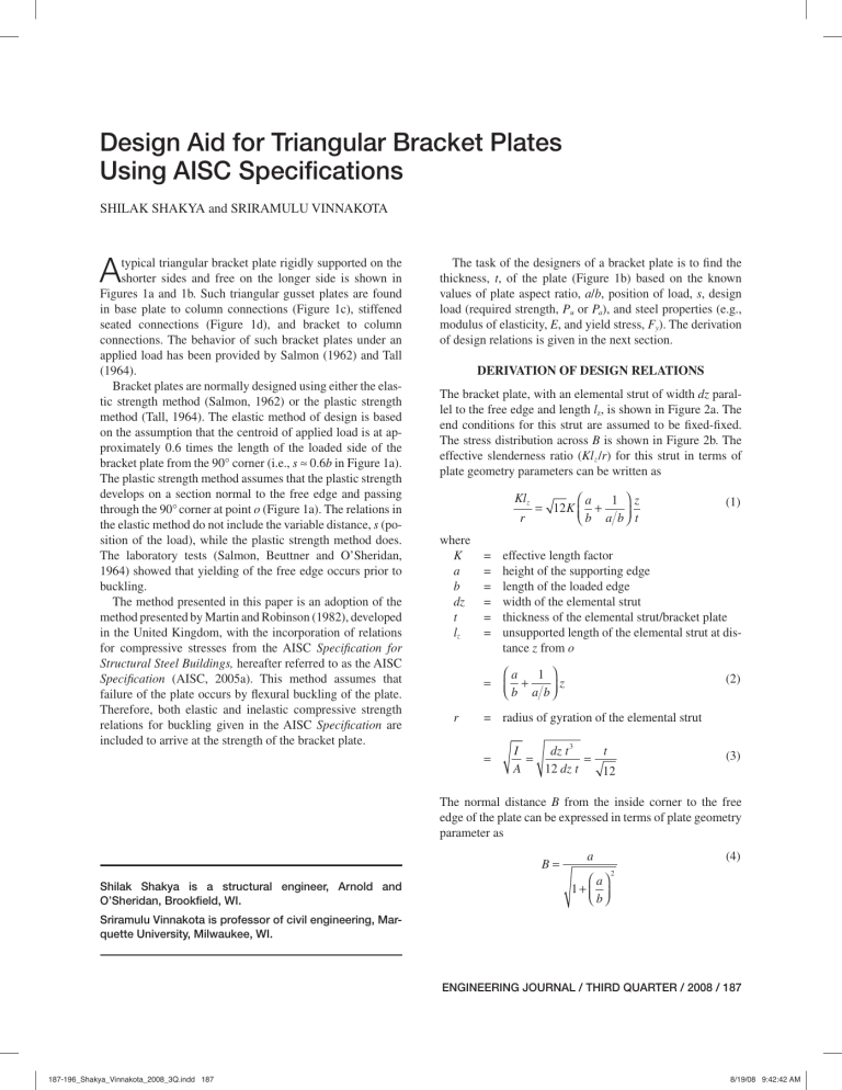
Design Aid for Triangular Bracket Plates Using AISC Specifications SHILAK SHAKYA and SRIRAMULU VINNAKOTA A typical triangular bracket plate rigidly supported on the shorter sides and free on the longer side is shown in Figures 1a and 1b. Such triangular gusset plates are found in base plate to column connections (Figure 1c), stiffened seated connections (Figure 1d), and bracket to column connections. The behavior of such bracket plates under an applied load has been provided by Salmon (1962) and Tall (1964). Bracket plates are normally designed using either the elastic strength method (Salmon, 1962) or the plastic strength method (Tall, 1964). The elastic method of design is based on the assumption that the centroid of applied load is at approximately 0.6 times the length of the loaded side of the bracket plate from the 90° corner (i.e., s ≈ 0.6b in Figure 1a). The plastic strength method assumes that the plastic strength develops on a section normal to the free edge and passing through the 90° corner at point o (Figure 1a). The relations in the elastic method do not include the variable distance, s (position of the load), while the plastic strength method does. The laboratory tests (Salmon, Beuttner and O’Sheridan, 1964) showed that yielding of the free edge occurs prior to buckling. The method presented in this paper is an adoption of the method presented by Martin and Robinson (1982), developed in the United Kingdom, with the incorporation of relations for compressive stresses from the AISC Specification for Structural Steel Buildings, hereafter referred to as the AISC Specification (AISC, 2005a). This method assumes that failure of the plate occurs by flexural buckling of the plate. Therefore, both elastic and inelastic compressive strength relations for buckling given in the AISC Specification are included to arrive at the strength of the bracket plate. The task of the designers of a bracket plate is to find the thickness, t, of the plate (Figure 1b) based on the known values of plate aspect ratio, a/b, position of load, s, design load (required strength, Pu or Pa), and steel properties (e.g., modulus of elasticity, E, and yield stress, Fy). The derivation of design relations is given in the next section. DERIVATION OF DESIGN RELATIONS The bracket plate, with an elemental strut of width dz parallel to the free edge and length lz, is shown in Figure 2a. The end conditions for this strut are assumed to be fixed-fixed. The stress distribution across B is shown in Figure 2b. The effective slenderness ratio (Kl z /r) for this strut in terms of plate geometry parameters can be written as Klz r where K a b dz t lz = = = = = = = r ⎛a 1 ⎞z = 12 K ⎜ + ⎝ b a b ⎟⎠ t (1) effective length factor height of the supporting edge length of the loaded edge width of the elemental strut thickness of the elemental strut/bracket plate unsupported length of the elemental strut at distance z from o ⎛a 1 ⎞ ⎜⎝ b + a b ⎟⎠ z (2) = radius of gyration of the elemental strut = I dz t 3 t = = A 12 dz t 12 (3) The normal distance B from the inside corner to the free edge of the plate can be expressed in terms of plate geometry parameter as B= Shilak Shakya is a structural engineer, Arnold and O’Sheridan, Brookfield, WI. a ⎛ a⎞ 1+ ⎜ ⎟ ⎝ b⎠ (4) 2 Sriramulu Vinnakota is professor of civil engineering, Marquette University, Milwaukee, WI. ENGINEERING JOURNAL / THIRD QUARTER / 2008 / 187 187-196_Shakya_Vinnakota_2008_3Q.indd 187 8/19/08 9:42:42 AM (a) Bracket Plate – side view (b) Bracket plate – end view Fig. 1. Triangular bracket plates. (a) Element strut (b) Stress distribution along B Fig. 2. Triangular bracket plate with an elemental strut. 188 / ENGINEERING JOURNAL / THIRD QUARTER / 2008 187-196_Shakya_Vinnakota_2008_3Q.indd 188 8/18/08 11:26:23 AM Table 1. Limiting Values of t*/b Fy (ksi) 0.5 0.75 1.0 1.5 2.0 2.5 3.0 36 0.0188 0.0210 0.0238 0.0303 0.0376 0.0453 0.0532 50 0.0222 0.0248 0.0281 0.0358 0.0444 0.0534 0.0627 The expressions for the critical stress, Fcr, given in the AISC Specification (Equations E3-2 and E3-3) are where α= For Klz ≤ 4.71 E r Fy Fy ⎛ ⎞ F Fcr = ⎜ 0.658 e ⎟ Fy ⎜⎝ ⎟⎠ For Klz r > 4.71 E Fy Fcr = 0.877 Fe where Fe (5) (6) = ⎛ Klz ⎞ ⎜ r ⎟ ⎝ ⎠ (7) 2 (12) The experimental work (Martin, 1979; Martin and Robinson, 1982) showed that the stress in the strip at the 90° corner is at yield and the stress in the strip near the free edge depends on the slenderness ratio of the strip at the free edge. Therefore, it is necessary to determine the boundary of the two regions where inelastic buckling and elastic buckling control the critical compressive stress of the strip. The location of this boundary denoted by z1 (measured from the inside 90° corner) can be determined from Equation 8 with the help of Equations 9 and 10 and is given here: = elastic critical buckling stress π2E Fy ⎛ a 1 ⎞1 + E ⎜⎝ b a b ⎟⎠ t 2 3K π z1 = 3 3 π = 2α 4 K E Fy ⎡ a b ⎢ ⎢⎣1 + a b ( ) 2 ⎤ ⎥t ⎥⎦ (13) This relation may be written in a dimensionless form by scaling with Equation 4 and simplifying. Thus, we have Substituting Equation 7 into Equations 5 and 6 and simplifying, we can rewrite Equations 5 and 6 For λ c ≤ 1.5 ( Fcr = 0.658 2 λc )F y (8) For λ c > 1.5 ⎛ 0.877⎞ Fcr = ⎜ 2 ⎟ Fy ⎝ λc ⎠ (9) where Klz Fy λc = rπ E (10) Using Equation 1, Equation 10 for the elemental strut at distance z from point o (see Figure 2a) can be expressed as λ cz = α z (11) z1 3 π = 4 K B ⎤ E ⎡ t b ⎢ 2 Fy ⎢ 1 + a b ⎥⎥ ⎣ ⎦ ( ) (14) Note that a value of z1/B > 1 from Equation 14 indicates that all the strips fail by inelastic buckling. Substituting this condition into Equation 14 results t* 4 K = 3 p b ⎛ a⎞ Fy 1+ ⎜ ⎟ E ⎝ b⎠ 2 (15) The limiting values of t*/b for different values of a/b and Fy /E are presented in Table 1. Note that if the actual value of t/b is less than the limiting value given in Table 1 for given a/b and Fy, the strength relation (see Equation 19) will have contributions of both inelastic and elastic buckling stresses. The nominal compressive strength based on the limit state of flexural buckling for a compression member is given by ENGINEERING JOURNAL / THIRD QUARTER / 2008 / 189 187-196_Shakya_Vinnakota_2008_3Q.indd 189 8/18/08 11:26:23 AM Pn = Ag Fcr where Ag (16) Pn s = gross area of member b3 E The relationships of the required strengths (Pu or Pa) to the nominal load, Pn, from the AISC Specification (AISC, 2005a) may be written as Pu = φc Pn (17a) Pn Ωc (17b) Pa = where φc Ωc Making use of Equation 14 in Equation 20 yields = 0.90 for load and resistance factor design (LRFD) = 1.67 for allowable stress design (ASD) The 90° corner of the plate is assumed to act as a hinge. The strut near the 90° corner could attain yield stress while the stresses in the farther struts depend on the slenderness ratio of the strut. See Figure 2b for the distribution of critical compressive stress. Equating sum of the moments of all elemental struts due to compressive forces about the hinge at point o to the external moment due to the externally applied load, we have B (18) Pn s = ∫ Fcr (t dz ) z 0 Restoring Equations 8 and 9 for Fcr and with the limits as shown in Figures 2b, Equation 18 can be expressed as B ⎡ z1 zdz ⎤ λ2 Pn s = tFy ⎢ ∫ 0.658 cz z dz + 0.877 ∫ 2 ⎥ ⎢⎣ 0 z1 λ cz ⎥ ⎦ (19) After integrating, simplifying and making Equation 19 dimensionless by scaling both sides with (b3E), we obtain ( ) ( ) 2 a b ⎛t⎞ π2 = 3 2 2 ⎜ ⎟ 2 b E 12 K ⎡ ⎤ ⎝ b⎠ ⎢⎣1 + a b ⎥⎦ Pn s 3 (20) ⎡ ⎛ B⎞ ⎤ × ⎢ 0.772877 + 0.877 loge ⎜ ⎟ ⎥ ⎝ z1 ⎠ ⎥⎦ ⎢⎣ ( ) ( ) 2 = 3 a b ⎛t⎞ π2 × 2 2 ⎜ ⎟ 2 ⎝ b⎠ 12 K ⎡ ⎤ 1+ a b ⎥ ⎣⎢ ⎦ (21) ⎧ ⎡ 4 K ⎪ × ⎨0.772877 + 0.877 loge ⎢ ⎢ 3 π ⎪⎩ ⎢⎣ 2 ⎤⎫ ⎛ a⎞ 1 ⎥ ⎪ 1+ ⎜ ⎟ ⎬ E ⎝ b⎠ t b⎥ ⎪ ⎥⎦ ⎭ Fy Knowing the applied load, the plate geometry, and the material properties, Equation 21 can be solved for t/b by trial and error or a simple computer program may be used to solve numerically. When B > 1, the compressive stress is controlled by z1 inelastic buckling in all strips and elastic buckling does not occur. For this case, Equation 18 after integration with the upper limit as B and simplification results in ( ) ( ) 2 a b π2 = 3 2 2 2 b E 12 K ⎡ ⎤ + 1 a b ⎢⎣ ⎥⎦ Pn s ⎛t⎞ ⎜⎝ b ⎟⎠ 3 (22) ⎛ 12 K 2 Fy [1+ ( a b )2 ] ⎞ ⎡ ⎤ ⎜ ⎟ ⎜⎝ ⎟⎠ π 2 E ( t b )2 ⎢ ⎥ 0 .6 6 58 − 1 ⎥ ×⎢ ⎢ ⎥ 2 loge 0.658 ⎢ ⎥ ⎣ ⎦ COMPARISON TO EXPERIMENTAL AND THEORETICAL RESULTS Equations 21 and 22 are used to compute the nominal strengths, Pn, and are compared with the experimental and theoretical results, Pexpt, (Salmon, Buettner and O’Sheridan, 1964; Martin, 1979; Martin and Robinson, 1982). This comparison is shown in Tables 2a, 2b and 2c in terms of Pexpt./ Pn. Note that the value of effective length factor, K, is taken equal to 0.5 in these calculations for comparison with other theoretical results. Also, the values of yield stresses in Tables 2a, 2b, and 2c are the measured values. The comparison shows that the authors’ developed relations predict nominal load closer to the experimental results than the other theoretical methods. The details of integration are shown in Appendix A. Note B that > 1 in the preceding equation. z1 190 / ENGINEERING JOURNAL / THIRD QUARTER / 2008 187-196_Shakya_Vinnakota_2008_3Q.indd 190 8/18/08 11:26:23 AM Table 2a. Comparison with Experimental Results of Salmon et al. (1964) (E = 29,000 ksi) Specimen No. b in. a in. t in. s in. Fy ksi Pexpt. kips 1 9.0 12.0 0.386 5.4 43.2 2 22.5 30.0 3 22.5 30.0 0.277 13.5 0.384 13.5 4 9.0 9.0 0.268 5 9.0 9.0 6 30.0 7 30.0 8 Pexpt./Pn Salmon et al. (1964) Martin (1979) Authors 97.8 1.87 1.56 1.41 41.2 63.3 1.58 1.56 1.43 43.2 125.8 1.18 1.54 1.34 5.4 41.2 40.0 1.91 1.37 1.18 0.378 5.4 43.2 69.5 2.25 1.40 1.26 30.0 0.268 18.0 41.2 49.5 2.19 1.54 1.37 30.0 0.385 18.0 43.2 101.7 1.52 1.41 1.20 13.5 9.0 0.271 8.1 41.2 31.3 2.00 1.26 1.10 9 13.5 9.0 0.374 8.1 43.2 64.5 2.85 1.52 1.37 10 30.0 20.0 0.276 18.0 41.2 35.8 1.60 1.27 1.21 11 30.0 20.0 0.384 18.0 43.2 80.1 1.55 1.42 1.28 12 18.0 9.0 0.274 10.8 41.2 29.8 2.10 1.42 1.38 13 18.0 9.0 0.387 10.8 43.2 46.6 2.21 1.25 1.19 14 30.0 15.0 0.373 18.0 43.2 57.6 1.70 1.37 1.39 15 30.0 15.0 0.373 18.0 43.2 58.5 1.73 1.39 1.41 Table 2b. Comparison with Experimental Results of Martin (1979) (E = 29,877 ksi) Specimen No. b in. a in. t in. s in. Fy ksi Pexpt. kips 1 5.71 5.71 0.240 3.15 43.9 2 5.83 11.61 0.257 4.02 3 5.94 11.77 0.255 4 4.92 4.92 0.254 5 4.92 4.92 6 4.80 7 4.72 Pexpt./Pn Salmon et al. (1964) Martin (1979) Authors 28.7 2.27 1.31 1.17 37.4 42.6 1.32 1.69 1.59 4.06 37.4 43.7 1.32 1.52 1.62 2.52 37.0 30.2 3.11 1.52 1.42 0.254 2.52 37.0 35.8 3.68 1.80 1.68 14.84 0.253 2.56 37.0 39.6 1.10 1.28 1.38 14.65 0.254 2.46 37.0 47.9 1.34 1.52 1.64 DESIGN AID TABLES In design problems, the values of E, Fy, a, b, φc Pn (= required strength, Pu in LRFD) or Pn / Ωc (= required strength, Pa in ASD), and s are known and the thickness, t, of the plate is to be determined. Therefore, design tables would become very helpful in the design process. Two design aids in tabular form, namely, Tables 3 and 4 are presented for steel with Fy = 36 ksi and 50 ksi, respectively. The plate aspect ratio, a/b, ranges from 0.50 to 3.00 and the dimensionless moment, Pn s/b3E, varies from 0.25 × 10⁻⁶ to 50 × 10-6 in these tables. Knowing the design load, the design procedure is straightforward and the various steps are enumerated as follows: 1. Compute a/b, the nominal load, and Pn s/b3E from the known design information. 2. Determine t/b from Table 3 or 4, depending on the steel grade. ENGINEERING JOURNAL / THIRD QUARTER / 2008 / 191 187-196_Shakya_Vinnakota_2008_3Q.indd 191 8/19/08 9:43:26 AM Table 2c. Comparison with Experimental Results of Martin and Robinson (1984) (E = 29,877 ksi) Specimen No. b in. a in. t in. s in. Fy ksi Pexpt. kips Pexpt./Pn Authors 1 3.94 3.94 0.157 1.97 54.8 14.7 1.00 2 7.87 7.87 0.157 3.94 54.8 19.8 0.99 3 7.87 7.87 0.157 3.94 54.8 21.3 1.07 4 11.81 11.81 0.157 5.91 54.8 17.7 0.93 5 15.75 15.75 0.157 7.88 54.8 15.0 0.87 6 15.75 15.75 0.157 7.88 54.8 15.6 0.90 7 19.69 19.69 0.157 9.85 54.8 17.5 1.11 8 19.69 19.69 0.157 9.85 54.8 18.0 1.14 9 7.87 1.97 0.157 3.94 54.8 4.9 1.66 10 7.87 3.94 0.157 3.94 54.8 12.3 1.28 11 7.87 3.94 0.157 3.94 54.8 13.0 1.36 12 7.87 5.91 0.157 3.94 54.8 19.0 1.19 13 7.87 7.87 0.157 3.94 54.8 19.5 0.98 14 7.87 7.87 0.157 3.94 54.8 20.7 1.04 15 7.87 9.84 0.157 3.94 54.8 24.1 1.12 16 7.87 9.84 0.157 3.94 54.8 27.0 1.26 17 7.87 11.81 0.157 3.94 54.8 24.6 1.15 18 7.87 11.81 0.157 3.94 54.8 27.3 1.28 19 7.87 15.75 0.157 3.94 54.8 24.6 1.30 20 7.87 15.75 0.157 3.94 54.8 25.0 1.32 21 7.87 19.69 0.157 3.94 54.8 26.4 1.65 22 7.87 19.69 0.157 3.94 54.8 27.0 1.69 23 7.87 23.62 0.157 3.94 54.8 23.4 1.76 24 7.87 23.62 0.157 3.94 54.8 26.4 1.98 EXAMPLES For comparative purposes, the following two examples (Salmon and Johnson, 1990; Tall, 1974) are reworked. Example 1 Determine the thickness required for a triangular bracket plate shown in Figure 3 to carry a factored load of 60 kips. Assume the load is located 15 in. from the face of support. Use the LRFD method with Fy = 36 ksi. Solution a/b = 20/25 = 0.8 Pn = Pu /φc = 60/0.9 = 66.7 kips Pn s/b3E = (66.7)(15)/[(253)(29,000)] = 2.208 × 10⁻⁶ Fig. 3. Triangular bracket plate for Example 1. 192 / ENGINEERING JOURNAL / THIRD QUARTER / 2008 187-196_Shakya_Vinnakota_2008_3Q.indd 192 8/19/08 9:43:54 AM Table 3. Nominal Strength of Triangular Bracket Plates Using AISC Column Strength Equations (Fy = 36 ksi, K = 0.65) Pns/b3E (ⴛ 10–6) Values of t/b (ⴛ 10–3) for a/b equal to 0.50 0.75 1.00 1.50 2.00 2.50 3.00 0.25 8.06 6.78 6.41 6.54 7.06 7.69 8.35 0.50 10.93 9.07 8.52 8.65 9.31 10.12 10.98 0.75 13.16 10.79 10.09 10.20 10.95 11.89 12.89 1.00 15.11 12.24 11.40 11.47 12.30 13.35 14.46 2.00 22.12 16.89 15.46 15.36 16.36 17.69 19.12 4.00 36.37 24.67 21.60 20.89 22.03 23.68 25.50 6.00 51.37 32.47 27.14 25.36 26.47 28.30 30.37 8.00 66.81 40.50 32.71 29.44 30.35 32.28 34.52 10.00 82.47 48.75 38.38 33.43 33.96 35.90 38.26 12.00 98.27 57.16 44.17 37.43 37.44 39.29 41.72 14.00 114.10 65.69 50.06 41.46 40.90 42.56 45.01 16.00 130.10 74.30 56.03 45.54 44.36 45.78 48.18 18.00 146.10 82.98 62.08 49.66 47.83 48.99 51.28 20.00 162.10 91.70 68.19 53.83 51.32 52.19 54.36 22.00 178.10 100.50 74.34 58.05 54.84 55.41 57.43 24.00 194.10 109.20 80.53 62.30 58.39 58.64 60.50 26.00 210.20 118.10 86.76 66.60 61.97 61.88 63.57 28.00 226.20 126.90 93.01 70.92 65.57 65.15 66.66 30.00 242.30 135.70 99.28 75.28 69.21 68.43 69.76 32.00 258.30 144.60 105.60 79.66 72.87 71.74 72.87 34.00 274.40 153.50 111.90 84.06 76.55 75.06 75.99 36.00 290.50 162.30 118.20 88.49 80.25 78.41 79.14 38.00 306.60 171.20 124.50 92.93 83.98 81.77 82.29 40.00 322.70 180.10 130.90 97.39 87.73 85.16 85.47 42.00 338.70 189.00 137.20 101.90 91.49 88.56 88.66 44.00 354.80 197.90 143.60 106.30 95.27 91.98 91.86 46.00 370.90 206.80 150.00 110.80 99.06 95.41 95.08 48.00 387.00 215.70 156.30 115.40 102.90 98.86 98.32 50.00 403.10 224.60 162.70 119.90 106.70 102.30 101.60 ENGINEERING JOURNAL / THIRD QUARTER / 2008 / 193 187-196_Shakya_Vinnakota_2008_3Q.indd 193 8/18/08 11:26:25 AM Table 4. Nominal Strength of Triangular Bracket Plates Using AISC Column Strength Equations (Fy = 50 ksi, K = 0.65) Pns/b3E (ⴛ 10–6) Values of t/b (ⴛ 10–3) for a/b equal to 0.50 0.75 1.00 1.50 2.00 2.50 3.00 0.25 7.76 6.57 6.22 6.37 6.89 7.51 8.17 0.50 10.42 8.73 8.24 8.40 9.05 9.86 10.71 0.75 12.44 10.33 9.72 9.87 10.63 11.56 12.55 1.00 14.15 11.67 10.94 11.08 11.91 12.95 14.05 2.00 19.74 15.81 14.66 14.71 15.75 17.07 18.48 4.00 29.74 22.03 20.00 19.75 21.00 22.67 24.47 6.00 40.02 27.58 24.35 23.66 25.00 26.90 28.97 8.00 50.66 33.14 28.37 27.05 28.40 30.46 32.75 10.00 61.56 38.79 32.35 30.16 31.46 33.64 36.09 12.00 72.65 44.55 36.35 33.12 34.30 36.54 39.13 14.00 83.85 50.42 40.39 36.01 36.98 39.26 41.95 16.00 95.14 56.37 44.49 38.88 39.56 41.85 44.62 18.00 106.50 62.39 48.63 41.76 42.09 44.33 47.16 20.00 117.90 68.48 52.82 44.64 44.58 46.74 49.61 22.00 129.30 74.61 57.05 47.54 47.07 49.10 51.98 24.00 140.80 80.79 61.33 50.46 49.56 51.43 54.30 26.00 152.30 87.00 65.64 53.40 52.05 53.74 56.57 28.00 163.70 93.23 69.98 56.36 54.54 56.05 58.81 30.00 175.30 99.49 74.35 59.34 57.05 58.36 61.04 32.00 186.80 105.80 78.75 62.34 59.56 60.67 63.25 34.00 198.30 112.10 83.16 65.37 62.09 62.98 65.46 36.00 209.80 118.40 87.60 68.41 64.63 65.29 67.67 38.00 221.40 124.70 92.05 71.46 67.18 67.62 69.88 40.00 232.90 131.00 96.52 74.54 69.74 69.95 72.10 42.00 244.50 137.40 101.00 77.63 72.32 72.28 74.31 44.00 256.00 143.70 105.50 80.74 74.91 74.63 76.53 46.00 267.60 150.10 110.00 83.85 77.51 76.98 78.75 48.00 279.20 156.50 114.50 86.99 80.12 79.34 80.98 50.00 290.70 162.80 119.00 90.13 82.75 81.72 83.22 From Table 3, with Fy = 36 ksi and using interpolation: t/b = 17.26 × 10⁻³ ⇒ t = 0.432 in. The thickness for the example problem by Salmon and Johnson (1990) is 0.58 in. Note the difference in the result could be due to not considering the effect of variable s in the design. Example 2 Determine the thickness of the triangular plate in the stiffened beam seat as shown in Figure 4. Use the ASD method with Fy = 36 ksi. Solution Neglect the plate material below the dashed line. 194 / ENGINEERING JOURNAL / THIRD QUARTER / 2008 187-196_Shakya_Vinnakota_2008_3Q.indd 194 8/19/08 9:44:27 AM a/b = 10/6 = 1.667 Pn = Ωc Pa = (1.67)(34) = 56.8 kips Pn s/b3E = (56.8)(3.8)/[(63)(29,000)] = 34.46 × 10⁻⁶ For shear rupture: Rn = 0.6 Fu Anv From Table 3 with Fy = 36 ksi and using interpolation: t/b = 81.38 × 10⁻³ ⇒ t = 0.49 in. The thickness for the example problem by Tall (1974) is 0.57 in. Note the difference in the result is due to not considering the effect of variable s in the design. Note that the design work also requires checking the bracket plate system for all the limit states for bracket plates as per AISC Specification Equations J4-1 to J4-4. These equations are also reproduced here. where Anv φc Ωc Based on the comparison of results developed relations with the results (Salmon et al., 1964; Martin, 1979; 1982) and the experimental results, sions can be made: The relations developed based on column strength equations from the AISC Specification are accurate and conservative. • The developed relations can also be used to size the stiffener plate in a stiffened seated connection as shown in Figure 1d with s = 0.8b [Refer to Figure 10-10b (AISC, 2005b)]. • The limiting value for plate thickness, t*, is established (see Equation 15 and Table 1) to avoid elastic buckling failure. • The equations developed are applicable to both ASD and LRFD design approaches. • The authors developed relations comparable to other theoretical relations in that they include most of the design parameters. For tensile rupture: where Fu φc Ωc (24) = minimum specified tensile strength = 0.75 (LFRD) = 2.00 (ASD) For shear yielding: Rn = 0.6 Fy Ag where φc Ωc (25) based on the authors’ of design methods by Martin and Robinson, the following conclu- • (23) where φc = 0.90 (LFRD) Ωc = 1.67 (ASD) Rn = Fu Ae = net area subject to shear = 0.75 (LFRD) = 2.00 (ASD) CONCLUSIONS For tensile yielding: Rn = Fy Ag (26) = 1.00 (LFRD) = 1.50 (ASD) NOMENCLATURE Fig. 4. Triangular bracket plate for Example 2. Ae = net effective area of the plate member Ag = gross area of the plate member Anv = net area subject to shear a = height of bracket b = length of the loaded side of plate B = normal distance from hinge (corner) to free edge of plate dz = width of the elemental strut E = modulus of elasticity Fcr = critical compressive stress Fe = elastic critical buckling stress Fu = minimum tensile stress of steel ENGINEERING JOURNAL / THIRD QUARTER / 2008 / 195 187-196_Shakya_Vinnakota_2008_3Q.indd 195 8/19/08 9:45:32 AM Fy = minimum yield stress of steel I = second moment of area of steel section K = effective length factor lz = length of strut at z distance from o REFERENCES Pa, Pu = service and factored load Pn, Rn = nominal design strength r = radius of gyration s = position of load t = thickness of bracket plate φc = resistance factor (load and resistance factor design) Ωc = safety factor (allowable stress design) APPENDIX A Substituting Equation 11 for λcz into Equation 19, we get B ⎡ z1 2 zdz ⎤ ⎥ Pn s = tFy ⎢ ∫ 0.658(αz ) z dz + 0.877 ∫ 2 ⎢⎣ 0 z1 (αz ) ⎥ ⎦ (A-1) Integrating Equation A-1, we have z B ⎤ ⎡ ⎡ α2z 2 ⎤ 1 0 658 . 0.877 ⎡⎣ loge z ⎤⎦ z ⎥ ⎢ ⎣ ⎦0 1 Pn s = tFy ⎢ 2 + ⎥ 2 2 0 658 log . α α e ⎢ ⎥ ⎣ ⎦ (A-2) Substituting for α and z1 using Equations 12 and 13, scaling both sides by b3E, and simplifying, Equation A-2 will reduce to Equation 20. AISC (2005a), Specification for Structural Steel Buildings, American Institute of Steel Construction, Chicago, IL. AISC (2005b), Steel Construction Manual, 13th ed., American Institute of Steel Construction, Chicago, IL. Martin, L.H. (1979), “Methods for the Limit State Design of Triangular Steel Gusset Plates,” Building and Environment, Vol. 14, pp. 147–155. Martin, L.H. and Robinson, S. (1982), “Experiments to Investigate Parameters Associated with the Failure of Triangular Steel Gusset Plates,” Joints in Structural Steelwork, the design and performance of Semi-Rigid and Rigid Joints in Steel and Composite Structures and Their Influence on Structural Behavior, John Wiley and Sons, New York, NY, pp. 1.74–1.91. Salmon, C.G. (1962), “Analysis of Triangular Bracket-Type Plates,” Journal of the Engineering Mechanics Division, ASCE, Vol. 88, EM6, pp. 41–87. Salmon, C.G., Buettner, D.R. and O’Sheridan, T.C. (1964), “Laboratory Investigation of Unstiffened Triangular Bracket Plates,” Journal of the Structural Division, ASCE, Vol. 90, No. ST2, pp. 257–278. Salmon, C.G. and Johnson, J.E. (1990), Steel Structures Design and Behavior, Harper & Row Publishers, 3rd ed., New York, NY, pp. 878–883. Tall, L. (1964), Structural Steel Design, The Ronald Press Company, 1st ed., New York, NY pp. 550–555. Tall, L. (1974), Structural Steel Design, The Ronald Press Company, 2nd ed., New York, NY pp. 586–591. 196 / ENGINEERING JOURNAL / THIRD QUARTER / 2008 187-196_Shakya_Vinnakota_2008_3Q.indd 196 8/18/08 11:26:25 AM
