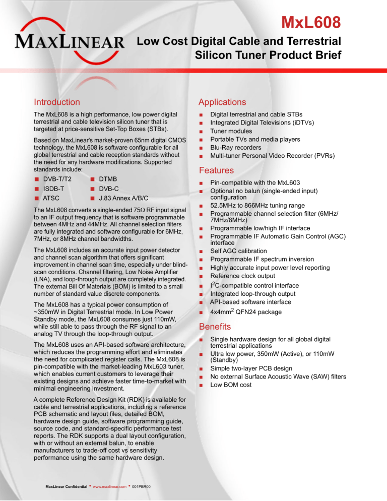
MxL608 Low Cost Digital Cable and Terrestrial Silicon Tuner Product Brief Introduction Applications The MxL608 is a high performance, low power digital terrestrial and cable television silicon tuner that is targeted at price-sensitive Set-Top Boxes (STBs). ■ ■ ■ ■ ■ ■ Based on MaxLinear's market-proven 65nm digital CMOS technology, the MxL608 is software configurable for all global terrestrial and cable reception standards without the need for any hardware modifications. Supported standards include: ■ ■ ■ DVB-T/T2 ISDB-T ATSC ■ ■ ■ DTMB DVB-C J.83 Annex A/B/C The MxL608 converts a single-ended 75 RF input signal to an IF output frequency that is software programmable between 4MHz and 44MHz. All channel selection filters are fully integrated and software configurable for 6MHz, 7MHz, or 8MHz channel bandwidths. The MxL608 includes an accurate input power detector and channel scan algorithm that offers significant improvement in channel scan time, especially under blindscan conditions. Channel filtering, Low Noise Amplifier (LNA), and loop-through output are completely integrated. The external Bill Of Materials (BOM) is limited to a small number of standard value discrete components. The MxL608 has a typical power consumption of ~350mW in Digital Terrestrial mode. In Low Power Standby mode, the MxL608 consumes just 110mW, while still able to pass through the RF signal to an analog TV through the loop-through output. The MxL608 uses an API-based software architecture, which reduces the programming effort and eliminates the need for complicated register calls. The MxL608 is pin-compatible with the market-leading MxL603 tuner, which enables current customers to leverage their existing designs and achieve faster time-to-market with minimal engineering investment. A complete Reference Design Kit (RDK) is available for cable and terrestrial applications, including a reference PCB schematic and layout files, detailed BOM, hardware design guide, software programming guide, source code, and standard-specific performance test reports. The RDK supports a dual layout configuration, with or without an external balun, to enable manufacturers to trade-off cost vs sensitivity performance using the same hardware design. MaxLinear Confidential • www.maxlinear.com • 001PBR00 Digital terrestrial and cable STBs Integrated Digital Televisions (iDTVs) Tuner modules Portable TVs and media players Blu-Ray recorders Multi-tuner Personal Video Recorder (PVRs) Features ■ ■ ■ ■ ■ ■ Pin-compatible with the MxL603 Optional no balun (single-ended input) configuration 52.5MHz to 866MHz tuning range Programmable channel selection filter (6MHz/ 7MHz/8MHz) Programmable low/high IF interface Programmable IF Automatic Gain Control (AGC) interface Self AGC calibration Programmable IF spectrum inversion Highly accurate input power level reporting Reference clock output ■ ■ ■ I2C-compatible control interface Integrated loop-through output API-based software interface ■ 4x4mm2 QFN24 package ■ ■ ■ ■ Benefits ■ ■ ■ ■ ■ Single hardware design for all global digital terrestrial applications Ultra low power, 350mW (Active), or 110mW (Standby) Simple two-layer PCB design No external Surface Acoustic Wave (SAW) filters Low BOM cost Low Cost Digital Cable and Terrestrial Silicon Tuner Product Brief MxL608 Block Diagram 52.5MHz–866MHz Input IF Out Loop-through Out Vagc CLK_OUT Reference Design PCB Ordering Information Part Number Description Package MxL608-AG-T Global Digital Cable and Terrestrial STB Tuner QFN24 MxL9608K01 MxL608 Evaluation Kit (EVK) for STB Applications - MaxLinear, Inc. 2051 Palomar Airport Road Suite 100 Carlsbad, CA 92011 760.692.0711 p. 760.444.8598 f. sales@maxlinear.com www.maxlinear.com The content of this document is furnished for informational use only, is subject to change without notice, and should not be construed as a commitment by MaxLinear, Inc.. MaxLinear, Inc. assumes no responsibility or liability for any errors or inaccuracies that may appear in the informational content contained in this guide. Complying with all applicable copyright laws is the responsibility of the user. Without limiting the rights under copyright, no part of this document may be reproduced into, stored in, or introduced into a retrieval system, or transmitted in any form or by any means (electronic, mechanical, photocopying, recording, or otherwise), or for any purpose, without the express written permission of MaxLinear, Inc. 10/15/13 001PBR00 2 MxL608 Data Sheet Revision History Revision History Document/Revision No. Release Date 001_608-02DSR 10/11/12 Change Description Updated: Title and minor text changes. Input tuning range. "Tuner General Specifications." ■ ■ ■ 001_608-01DSR 09/28/12 Updated: "MxL608 IC Block Diagram" figure. "Digital Supported IF Frequencies" table. ■ ■ 09/19/12 Initial release. M ax Li ne ar C on fid en tia l 001_608-00DSR MaxLinear Confidential 10/11/12 001_608-02DSR ii MxL608 Data Sheet Table of Contents Table of Contents General Description..................................................................................................................... i Applications ................................................................................................................................. i Features ........................................................................................................................................ i Supported Standards................................................................................................................... i Introduction ................................................................................................................................. 1 Glossary .............................................................................................................................................1 l IC Block Diagram ........................................................................................................................ 4 tia Pin Information............................................................................................................................ 5 en Pin Configuration ..............................................................................................................................5 Pin Description ..................................................................................................................................6 on fid RF Interface ................................................................................................................................. 6 I2C Interface ................................................................................................................................ 6 Supply and Ground..................................................................................................................... 7 ne ar C Analog and Digital I/O................................................................................................................. 7 Electrical Specifications............................................................................................................. 8 Absolute Maximum Ratings .............................................................................................................8 Operating Conditions........................................................................................................................8 Li Digital I/O Specifications ..................................................................................................................9 ax Tuner General Specifications...........................................................................................................9 Current Consumption .....................................................................................................................11 M Crystal Requirements .....................................................................................................................11 Supported Crystal Frequencies .....................................................................................................11 Supported IF Frequencies ..............................................................................................................11 Supply Voltage Ramp-Up Rules.....................................................................................................12 Reset Timing Rules .........................................................................................................................13 Operating Modes .............................................................................................................................13 ESD Performance ............................................................................................................................13 Packaging .................................................................................................................................. 14 Thermal Via Design .........................................................................................................................15 Thermal Information .................................................................................................................15 Ordering Information ................................................................................................................ 15 MaxLinear Confidential 10/11/12 001_608-02DSR iii MxL608 Data Sheet Table of Contents Appendix.................................................................................................................................... 16 AS Pin Hardware Configuration and Resistor Tolerance Requirement .....................................16 Negative Resistance........................................................................................................................16 GPO Control.....................................................................................................................................17 Operating Modes Control ...............................................................................................................17 AGC Voltage Range.........................................................................................................................17 Supply Ripple Susceptibility ..........................................................................................................17 M ax Li ne ar C on fid en tia l FBE and In-Band Ripple Definition ................................................................................................18 MaxLinear Confidential 10/11/12 001_608-02DSR iv MxL608 Data Sheet List of Figures List of Figures Figure 1: MxL608 IC Block Diagram.............................................................................................................4 Figure 2: Pin Configuration...........................................................................................................................5 Figure 3: Supply Voltage Ramp-Up Rule ...................................................................................................12 Figure 4: Reset Timing Rule.......................................................................................................................13 Figure 5: Packaging....................................................................................................................................14 Figure 6: AS Pin Hardware Configuration and Resistor Tolerance Requirement.......................................16 Figure 7: GPO Control................................................................................................................................17 M ax Li ne ar C on fid en tia l Figure 8: FBE and In-Band Ripple Definition..............................................................................................18 MaxLinear Confidential 10/11/12 001_608-02DSR V MxL608 Data Sheet List of Tables List of Tables Table 1: Standards Compliance Matrix ........................................................................................................1 Table 2: Glossary .........................................................................................................................................1 Table 3: Pin Names ......................................................................................................................................6 Table 4: RF Interface....................................................................................................................................6 Table 5: I2C Interface ...................................................................................................................................6 Table 6: Supply and Ground.........................................................................................................................7 Table 7: Analog and Digital I/O.....................................................................................................................7 tia l Table 8: Absolute Maximum Ratings............................................................................................................8 Table 9: Operating Conditions......................................................................................................................8 en Table 10: Digital I/O Specifications...............................................................................................................9 on fid Table 11: Tuner General Specifications .......................................................................................................9 Table 12: Current Consumption .................................................................................................................11 Table 13: Crystal Requirements .................................................................................................................11 Table 14: Supported Crystal Frequencies ..................................................................................................11 ne ar C Table 15: Digital Supported IF Frequencies ...............................................................................................11 Table 16: Reset Timing Rules ....................................................................................................................13 Table 17: Operating Modes ........................................................................................................................13 Table 18: Thermal Information ...................................................................................................................15 Li Table 19: Ordering Information...................................................................................................................15 M ax Table 20: AS Pin Hardware Configuration and Resistor Tolerance Requirement......................................16 MaxLinear Confidential 10/11/12 001_608-02DSR VI MxL608 Data Sheet Introduction Introduction The MxL608 is a highly integrated, low power silicon tuner IC that targets low cost terrestrial set-top box applications. The MxL608 is compliant with DVB-T and DTMB specifications for RF performance. The MxL608 is a subset of the MxL603 tuner, which is fully compliant with all global terrestrial standards. The following table lists the complete description of the standards compliance. Table 1: Standards Compliance Matrix Broadcast Standard DVB-T2, ISDB-T MxL603 MxL608 - • • • • • J.83 annex A, C (DVB-C) - en J.83 annex B - l ATSC • tia DVB-T, DTMB on fid The MxL608 supports an input tuning range from 52.5MHz to 866MHz. A signal at the 75Ω RF input is filtered and converted to a programmable IF output up to 44MHz. The AGC, LO generation, channel selection, and LT output functions are completely integrated on the chip, which simplifies board-level design. All functions of the IC can be controlled via an I2C interface. Driver integration is made easy through the use of simple software APIs. ne ar C The high level of integration enables a very compact, cost-effective design with few external components, low BOM costs and low power consumption. Glossary Table 2: Glossary µ µW Degree M ° Description ax Acronym/Abbreviation Li The MxL608 is available in a 4mm x 4mm2 24-pin QFN package. Micro MicroWatt kΩ kiloOhm Ω Ohm AC Alternating Current AGC Automatic Gain Control API Application Programming Interface AS Address Selection ATSC Advanced Television Systems Committee BE Back-End BOM Bill Of Materials BW Band Width MaxLinear Confidential 10/11/12 001_608-02DSR 1 MxL608 Data Sheet Glossary Table 2: Glossary (Continued) Acronym/Abbreviation Description CDM Charged Device Model CMOS Complementary Metal Oxide Semiconductor dB deciBel dBc deciBels relative to the carrier DTMB Digital Terrestrial Multimedia Broadcast DVB-C Digital Video Broadcasting—Cable DVB-T DVB—Terrestrial DVB—Terrestrial Second Generation EMI Electro-Magnetic Interference ESD Electro-Static Discharge FBE Filter Band Edge FEC Forward Error Correction GD Group Delay GHz GigaHertz GND Ground GPIO General Purpose Input/Output HBM Human Body Model I2C Inter-Integrated Circuit IC Integrated Circuit IF Intermediate Frequency I/O Input/Output I/Q In-phase and Quadrature ITU-T International Telecommunication Union—Telecommunications kHz kiloHertz LNA Low Noise Amplifier LT LTE tia en on fid ne ar C Li Local Oscillator ax LSB Least Significant Bit M LO l DVB-T2 Loop Through Long Term Evolution mA milliAmp MHz MegaHertz mm millimeter MoCA Multimedia over Coax Alliance MSB Most Significant Bit mW milliWatt NF Noise Figure NTSC National Television System Committee PAL Phase Alternating Line pF picoFarad PLL Phase Locked Loop MaxLinear Confidential 10/11/12 001_608-02DSR 2 MxL608 Data Sheet Glossary Table 2: Glossary (Continued) Description ppm parts per million PVR Personal Video Recorder QAM Quadrature Amplitude Modulation QEF Quasi Error Free QFN Quad Flat No-leads RF Radio Frequency RoHS Restriction of Hazardous Substances RSSI Received Signal Strength Indication SAW Surface Acoustic Wave SoC System on a Chip TS Transport Stream V Volt W Watt WiFi Wireless Fidelity Xtal Crystal oscillator M ax Li ne ar C on fid en tia l Acronym/Abbreviation MaxLinear Confidential 10/11/12 001_608-02DSR 3 MxL608 Data Sheet IC Block Diagram IC Block Diagram Figure 1 illustrates the architecture of the MxL608 tuner. The chip utilizes a proprietary architecture, which achieves the required channel selection using a multistage channel filter. The RF input is mixed to a fixed frequency, followed by channel filtering, and then mixed to a programmable IF frequency. Anti-alias filtering after the second mixing stage removes any out-of-band harmonics. A tunable IF LO allows for programmable IF frequencies. The AGC is distributed throughout the signal path for optimum noise and linearity performance through one AGC line. 52.5MHz–866MHz Input Channel Filtering IF Out Loop-Through Out I2C IF Synth en RF Synth on fid Synth Calibration tia l LNA Crystal Reference Gain Control Vagc Voltage Regulator ne ar C CLK_OUT M ax Li Figure 1: MxL608 IC Block Diagram MaxLinear Confidential 10/11/12 001_608-02DSR 4 MxL608 Data Sheet Pin Information Pin Information VDD_1p8 XTAL_P XTAL_N 21 20 19 l VDD_3p3 22 tia LT_AC_GND 23 NC 1 18 LNA_INP 2 LNA_INN 3 en LT_OUT 24 Pin Configuration VDD_1p8 4 GPO 5 AGC 6 7 8 9 10 11 12 IF_OUTN AS RESET_N VDD_3p3 VDD_1p8 ne ar C IF_OUTP Li ax M 17 SDA 16 SCL 15 VDD_IO 14 GND_DIG 13 VDD_1p2 on fid MxL 608 CLK_OUT Figure 2: Pin Configuration MaxLinear Confidential 10/11/12 001_608-02DSR 5 MxL608 Data Sheet Pin Description Pin Description Table 3: Pin Names Pin Name Pin # Pin Name 1 NC 13 VDD_1p2 2 LNA_INP 14 GND_DIG 3 LNA_INN 15 VDD_IO 4 VDD_1p8 16 SCL 5 GPO 17 SDA 6 AGC 18 CLK_OUT 7 IF_OUTP 19 XTAL_N 8 IF_OUTN 20 XTAL_P 9 AS 21 VDD_1p8 10 RESET_N 22 VDD_3p3 11 VDD_3p3 23 LT_AC_GND 12 VDD_1p8 24 LT_OUT on fid en tia l Pin # Table 4: RF Interface Pin Name Direction LNA_INP LNA_INN Input LT_OUT Output LT_AC_GND Output ne ar C RF Interface Description Differential RF inputs; differential input impedance of 75Ω. Single-ended, loop through output. ax Li AC ground for LT. M I2C Interface Table 5: I2C Interface Pin Name Direction Description SCL Input Clock. SDA Bidirectional Pull-down data pin. AS Input Address selection (see "AS Pin Hardware Configuration and Resistor Tolerance Requirement" on page 16 for details). MaxLinear Confidential 10/11/12 001_608-02DSR 6 MxL608 Data Sheet Supply and Ground Supply and Ground Table 6: Supply and Ground Pin Name Direction Description VDD_3p3 Input Supply voltage for 3.3V. VDD_1p8 Input Supply voltage for 1.8V. VDD_IO Input Supply voltage for I/O interface. GND Input Connect to ground. GND_DIG Input Ground for digital circuit blocks. en tia l Analog and Digital I/O Table 7: Analog and Digital I/O Direction Description CLK_OUT Output Clock output is programmable to div-by-1 or div-by-6 of the crystal for clock re-use. RESET_N Input Reset. IF_OUTP IF_OUTN Output IF output. GPO Output Input XTAL_N Input ne ar C Input XTAL_P General purpose output (see "GPO Control" on page 17 for details). Automatic gain control. Crystal positive input. Crystal negative input; can be used as an external system clock input pin if no crystal is used. M ax Li AGC on fid Pin Name MaxLinear Confidential 10/11/12 001_608-02DSR 7 MxL608 Data Sheet Electrical Specifications Electrical Specifications Absolute Maximum Ratings Important! The stresses above what is listed under the following table may cause permanent damage to the device. This is a stress rating only—functional operation of the device above what is listed under the following table or any other conditions beyond what MaxLinear recommends is not implied. Exposure to conditions above the recommended extended periods of time may affect device reliability. Table 8: Absolute Maximum Ratings Minimum Maximum Units VDD_3p3 –0.3 3.6 V VDD_1p8 –0.3 2.0 V VDD_IO –0.3 3.6 AGC –0.3 3.6 SDA, SCL –0.3 3.6 AS –0.3 GPO –0.3 –65 Soldering Temperature - Operating Conditions Table 9: Operating Conditions tia en V 3.6 V 3.6 V 15 dBm 150 oC 265 oC Symbol Minimum Typical Maximum Units VDD_3p3 3.1 3.3 3.6 V VDD_1p8 1.7 1.8 1.9 V I/O Supply (1.8V Mode) VDD_IO 1.7 1.8 1.9 V I/O Supply (3.3V Mode) VDD_IO 3.1 3.3 3.6 V AGC Range (see "AGC Voltage Range" on page 17) AGC 0 - 3.3 V AS AS 0 - 3.6 V Reset Voltage Supply RESET_N 0 - VDD_IO V Operating Temperature T 0 25 85 oC Junction Temperature Tj - - 125 o Li Parameter V V on fid - Storage Temperature ne ar C RF Input Power l Parameter 3.3V Supply M ax 1.8V Supply C MaxLinear Confidential 10/11/12 001_608-02DSR 8 MxL608 Data Sheet Digital I/O Specifications Digital I/O Specifications Table 10: Digital I/O Specifications Parameter Symbol Minimum Typical Maximum Units - - V - 0.4 V 3.3V Configuration (VDD_IO = 3.3V) VOH (@ 3mA source) VDD_IO –0.4 Output Logic Voltage on All Digital I/O Pins VOL (@ 3mA sink) Input Logic Voltage on All Digital I/O Pins VIH 2.2 - - V VIL - - 0.8 V - - V - 0.2 V - - V - 0.4 V 1.1 VIL - en VIH on fid Input Logic Voltage on All Digital I/O Pins tia VOH (@ 3mA source) VDD_IO –0.2 Output Logic Voltage on All Digital I/O Pins VOL (@ 3mA sink) l 1.8V Configuration (VDD_IO = 1.8V) Tuner General Specifications ne ar C All specifications apply to the conditions defined in "Operating Conditions" on page 8, measured at IF = 7/ 8MHz and across the RF frequency range. Table 11: Tuner General Specifications Parameter System Input Return Loss 75Ω System Li RF Frequency Range Channel Bandwidth ax Maximum Voltage Gain (LT Off) Symbol Minimum Typical Maximum Units S11 - –8 - dB fRF 44 - 866 MHz - - 7, 8 - MHz Gmax 90 94 - dB AGC 110 114 - dB Noise Figure (LT Off) NF - 4.2 - dB - 112 115 - dBuVrms M Gain Control Range (LT Off) Output 1dB Compression IF LO Feed-through Rejection RF input > –70dBm DCOS - - –45 dBc I/Q Imbalance RF input > –70dBm IQI - - –45 dBc Supply Ripple Susceptibility (1kHz–500kHz, see "Supply Ripple Susceptibility" on page 17) - - - 20 mVpp RF Input Leakage - - –90 - dBm RF Frequency Range fLT 52.5 - 866 MHz Gain GLT –2 1 3 dB Noise Figure (LT only) NFLT - 9 - dB LT Output Return Loss S22LT - –10 - dB LT Output MaxLinear Confidential 10/11/12 001_608-02DSR 9 MxL608 Data Sheet Tuner General Specifications Table 11: Tuner General Specifications (Continued) Parameter Symbol Minimum Typical Maximum Units FBE - 3.25 - MHz FBE - 3.75 - MHz BW=7MHz GD - - 50 ns BW=8MHz GD - - 50 ns BW=7MHz - - 2 - dB BW=8MHz - - 2 - dB Picture (4.75MHz) - - 85 - dB Sound (3.75MHz) - - 60 - dB Picture (5.25MHz) - - Sound (4.75MHz) - - In-Band Amplitude Variation BW= 7MHz Attenuation of Adjacent Analog Channel (measured at the offset from the center of the band) BW= 8MHz at 1kHz Offset - at 10kHz Offset - at 100kHz Offset - dB 85 - dB –77 –82 - dBc/Hz - –77 –82 - dBc/Hz - - –87 - dBc/Hz - - –99 - dBc/Hz - - 350 - Ω Input Level to the XTAL_N Pin when using an External Clock - - 600 - mVpp ne ar C - - - Phase Noise at 250Hz Offset on fid Synthesizer 85 tia GD Across ± Band Edge (Peak-to-Peak) en Channel Select FBE Frequency Definition BW=7MHz (measured at the offset from the center of the band; see "FBE and In-Band Ripple Definition" BW=8MHz on page 18) l Channel Select Filter for Digital Terrestrial Crystal Oscillator ax Li Negative Resistance (see "Negative Resistance" on page 16) Others M IF Output Impedance (Singleended) IF Output Level (Programmable) High IF (>=36MHz) - - 153 - Ω Low IF - - 305 - Ω Low IF - 400 800 1250 mVp-p AGC Input Impedance - - 55K - Ω Clock Output Swing - - 600 - mVpp MaxLinear Confidential 10/11/12 001_608-02DSR 10 MxL608 Data Sheet Current Consumption Current Consumption The current consumption accounts for temperature and process variations. The typical condition applies to typical conditions defined in the recommended "Operating Conditions" on page 8. Note: When LT is on, add an additional 20mA current consumption on the VDD_3p3 supply pin to the values in the following table. Table 12: Current Consumption Mode Operating Frequency Digital Terrestrial RF=52.5MHz–866MHz Supply Pin Minimum Typical Maximum Units VDD_3p3 54 65 mA VDD_1p8 125 150 mA Crystal Requirements Table 13: Crystal Requirements Minimum Typical en Parameter tia l The MxL608 only supports the fundamental mode crystals. The default crystal frequency used is 16MHz. Maximum Units 50 Ω Frequency Accuracy (including Temperature and Tolerance) –60 - +60 ppm Aging - ±3 - ppm/year - 18 - pF - 250 - µW - 25 on fid ESR Load Capacitance ne ar C Drive Level Supported Crystal Frequencies Table 14: Supported Crystal Frequencies Units Default. MHz Optional. ax MHz M 24 Comment Li Crystal Frequencies 16 Supported IF Frequencies The MxL608 also supports other IF frequencies not listed in the following table—contact MaxLinear’s Sales and Application for other support. Table 15: Digital Supported IF Frequencies Item Low IF (MHz) Standard IF (MHz) Bandwidth (MHz) Comment DVB-T 5 36.15, 44.0 7.8 Programmable channel BW. DTMB - 36.15 8 - MaxLinear Confidential 10/11/12 001_608-02DSR 11 MxL608 Data Sheet Supply Voltage Ramp-Up Rules Supply Voltage Ramp-Up Rules The MxL608 chip is designed to support an arbitrary power-up sequence for the three power supplies, as illustrated in the following figure. The three supplies can be powered up in an arbitrary order. The only requirement is to keep RESET_N low during the power-up. The RESET_N signal can be released after all voltage supplies have been stable for at least 10µs (T1≥ 10µs). Power-up Sequence en tia l VDD_3p3 on fid VDD_1p8 VDD_IO RESET_N ne ar C T1 M ax Li Figure 3: Supply Voltage Ramp-Up Rule MaxLinear Confidential 10/11/12 001_608-02DSR 12 MxL608 Data Sheet Reset Timing Rules Reset Timing Rules If the IC needs to reset while the chip is in a fully operational mode, the minimum timing (tRST) for the low state is 10µs. Table 16: Reset Timing Rules Symbol Minimum Typical Maximum Units Reset Timing tRST 10 - - µs en Figure 4: Reset Timing Rule tia l Parameter on fid Operating Modes For more details, see "Operating Modes Control" on page 17. Table 17: Operating Modes ne ar C Note: The LT can be on or off for all operation modes. When LT is on, add an additional 67mW power consumption to the values in the following table. Mode Control Typical Power Description Sleep Upon reset 26mW ■ On-chip digital regulator is on. I2C M Standby ax Li ■ Xtal and clock-out are on. control 26mW ■ I2C is active. ■ Register value is at default. ■ RF section is inactive. ■ LT is not enabled. ■ On-chip digital regulator is on. ■ Xtal oscillator and clock-out are on. ■ I2C is active. ■ Register value is the same as the previous state. ■ RF section is inactive. ■ LT is not enabled. Active I2C control 403mW ■ Tuner is fully operational in the digital terrestrial mode. ■ LT is not enabled. ESD Performance All pins pass the ESD performance of 2000V using the HBM and of 250V using the CDM. MaxLinear Confidential 10/11/12 001_608-02DSR 13 MxL608 Data Sheet Packaging Packaging QFN24 package dimensions = 4mm x 4mm x 0.85mm3. Thermal resistance (junction to ambient) = 43oC/W. ne ar C on fid en tia l ■ ■ M ax Li Figure 5: Packaging MaxLinear Confidential 10/11/12 001_608-02DSR 14 MxL608 Data Sheet Thermal Via Design Thermal Via Design To take full advantage of the QFN thermal performance, thermal vias are needed to provide a thermal path from the top to the inner/bottom layers of the PCB board for heat transfer. Important! MaxLinear recommends following the thermal via design described in Figure 5. Thermal Information TJunction = TAmbient + ThetaJa × Power Dissipation Table 18: Thermal Information Value/Condition Unit Thermal Resistance (Junction to Ambient) 43 o PCB Condition (Thermal Resistance Calculation) JEDEC JESD 51-5 - Air Flow Condition 0 ms tia l Parameter C/W 4 to 9 - Via Pitch 1–1.2 mm 0.25–0.33 mm en Number of Vias on fid Via Size (Diameter) Table 19: Ordering Information ne ar C Ordering Information Marketing Part Number Ordering Part Number Package Dimension Shipping MxL608 MxL608-AG-T SAWN QFN24 4mm x 4mm x 0.85mm Tray MxL608 MxL608-AG-R SAWN QFN24 4mm x 4mm x 0.85mm3 Tape and Reel M ax Li 3 MaxLinear Confidential 10/11/12 001_608-02DSR 15 MxL608 Data Sheet Appendix Appendix AS Pin Hardware Configuration and Resistor Tolerance Requirement VDD_3p3 MxL608 R1 tia l Pin 9 AS on fid en R2 ne ar C Figure 6: AS Pin Hardware Configuration and Resistor Tolerance Requirement Table 20: AS Pin Hardware Configuration and Resistor Tolerance Requirement I2C Address 96 R2 Open Short 30kΩ ± 5% 15kΩ ± 5% Li 97 R1 ax 98 60kΩ ± 5% Short Open M 99 30kΩ ± 5% Negative Resistance The negative resistance is specified for the crystal oscillator of the tuner in the following configuration: ■ ■ Uses a 16MHz (ABLS2-16.000MHz-D4Y-T) crystal from Abracon, a crystal manufacturer. On-chip crystal loading capacitors is programmed to 25pF. MaxLinear Confidential 10/11/12 001_608-02DSR 16 MxL608 Data Sheet GPO Control GPO Control The MxL608 provides one GPO pin for external circuit control. The GPO pin is open drain and requires an external pull-up resistor. The VDD voltage range can be supported from 1.8V to 3.3V. VDD R Pin 5 MxL608 GPO en Figure 7: GPO Control tia l External Device on fid Operating Modes Control AGC Voltage Range ne ar C The MxL608 supports the three operating modes of Sleep, Standby, and Active. The MxL608 is in the Sleep mode after the reset signal asserts. All the registers are in the default value. After a certain tuning sequence (e.g., channel frequency, BW, IF, etc.), the MxL608 operates in the Active mode. To save power while not in use, program the MxL608 into the Standby mode. In Standby mode, all the registers are stored from the Active mode and unnecessary blocks are shut off. During the switch of Active and Standby modes, the clock output has no disturbance and the GPO status remains the same. ax Li The maximum voltage AGC pin can support is up to 3.6V, but the effective range is from 0 to approximately 2.4V. M Supply Ripple Susceptibility For details, refer to the MxL608 Digital Tuner Reference Design Guide (001-DGR). MaxLinear Confidential 10/11/12 001_608-02DSR 17 MxL608 Data Sheet FBE and In-Band Ripple Definition FBE and In-Band Ripple Definition The FBE and in-band ripple are defined in the plot illustrated in the following figure. Band edge Inband ripple M ax Li ne ar C on fid en tia l Figure 8: FBE and In-Band Ripple Definition MaxLinear, Inc. 2051 Palomar Airport Road, Suite 100 Carlsbad, CA 92011 760.692.0711 p. 760.692.0712 f. www.maxlinear.com The content of this document is furnished for informational use only, is subject to change without notice, and should not be construed as a commitment by MaxLinear, Inc.. MaxLinear, Inc. assumes no responsibility or liability for any errors or inaccuracies that may appear in the informational content contained in this guide. Complying with all applicable copyright laws is the responsibility of the user. Without limiting the rights under copyright, no part of this document may be reproduced into, stored in, or introduced into a retrieval system, or transmitted in any form or by any means (electronic, mechanical, photocopying, recording, or otherwise), or for any purpose, without the express written permission of MaxLinear, Inc. MaxLinear, Inc. may have patents, patent applications, trademarks, copyrights, or other intellectual property rights covering subject matter in this document. Except as expressly provided in any written license agreement from MaxLinear, Inc., the furnishing of this document does not give you any license to these patents, trademarks, copyrights, or other intellectual property. Trademarks Company and product names may be registered trademarks or trademarks of the respective owners with which they are associated. Copyright © 2012 MaxLinear, Inc. All rights reserved. 10/11/12 001_608-02DSR 18
