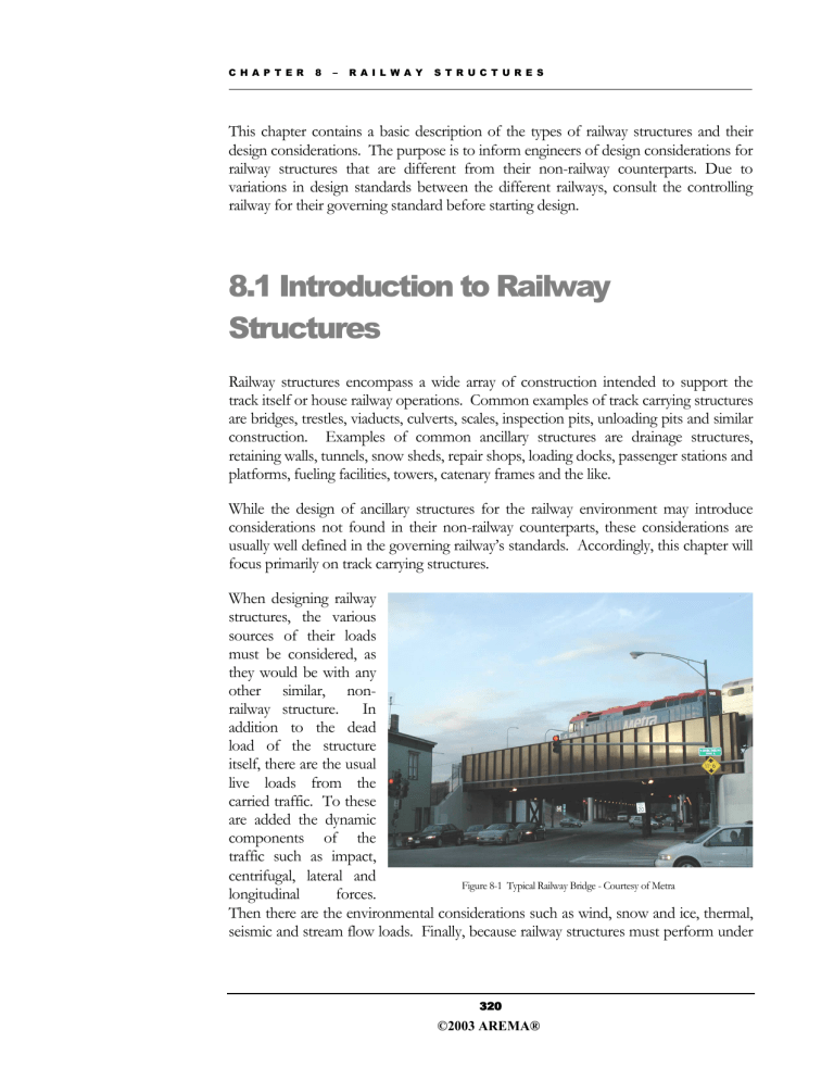
C H A P T E R 8 – R A I L W A Y S T R U C T U R E S This chapter contains a basic description of the types of railway structures and their design considerations. The purpose is to inform engineers of design considerations for railway structures that are different from their non-railway counterparts. Due to variations in design standards between the different railways, consult the controlling railway for their governing standard before starting design. 8.1 Introduction to Railway Structures Railway structures encompass a wide array of construction intended to support the track itself or house railway operations. Common examples of track carrying structures are bridges, trestles, viaducts, culverts, scales, inspection pits, unloading pits and similar construction. Examples of common ancillary structures are drainage structures, retaining walls, tunnels, snow sheds, repair shops, loading docks, passenger stations and platforms, fueling facilities, towers, catenary frames and the like. While the design of ancillary structures for the railway environment may introduce considerations not found in their non-railway counterparts, these considerations are usually well defined in the governing railway’s standards. Accordingly, this chapter will focus primarily on track carrying structures. When designing railway structures, the various sources of their loads must be considered, as they would be with any other similar, nonrailway structure. In addition to the dead load of the structure itself, there are the usual live loads from the carried traffic. To these are added the dynamic components of the traffic such as impact, centrifugal, lateral and Figure 8-1 Typical Railway Bridge - Courtesy of Metra longitudinal forces. Then there are the environmental considerations such as wind, snow and ice, thermal, seismic and stream flow loads. Finally, because railway structures must perform under 320 ©2003 AREMA® C H A P T E R 8 – R A I L W A Y S T R U C T U R E S heavier loads, have longer service lives, and dissimilar maintenance constraints compared to their highway counterparts, other factors, including fatigue and maintenance issues, tend to influence railway structure design more than roadway structures. Once the designer has established the first pass at the load environment for the subject structure, the primary difference between a highway structure and a railway structure should become obvious. In the typical railway structure, the live load dominates all of the other design considerations. For the engineer accustomed to highway bridge design, where the dead load of the structure itself tends to drive the design considerations, this marks a substantial divergence from the norm. Specifically, the unacceptability of high deflections in railway structures, maintenance concerns and fatigue considerations render many aspects of bridge design common to the highway industry unacceptable in the railway environment. Chief among these are welded connections and continuous spans. 8.2 Major Bridge Components30 In general terms, the major components of track carrying structure are very similar to their non-railway counterparts. In addition to the types of construction, the engineer must also choose from among the available material alternatives. Generally, these are limited to timber, concrete and steel, or a combination of the three. Exotic materials can also be considered, but they are beyond the scope of this book. Each material has its specific advantages. Timber is economical, but has strength and life limitations. Structural timber of the size and grade traditionally used for railway structures is getting more difficult to obtain at a price competitive with concrete or steel. Concrete is also economical, but its strength to weight ratio is poor. Steel has a good strength to weight ratio, but is expensive. The material chosen for the spans will generally determine the designation of the bridge. For instance, steel beam spans on timber piles will be considered a steel bridge. The point where one form of construction with a certain type of material becomes advantageous over another is a matter of site conditions, span length, tonnage carried and railway preference. While initial cost of construction is a major point in the decision process, the engineer must keep in mind such additional factors as construction under traffic and the long-term maintainability of the final design. Selected materials from “Railway Track & Structures Cyclopedia,” 1955 Edition, Simmons-Boardman Publishing Company 30 321 ©2003 AREMA® C H A P T E R 8 – R A I L W A Y S T R U C T U R E S The nature of the obstacle being crossed will drive most superstructure design decisions with the ultimate goal to achieve the least overall lifecycle cost for the structure. For short (height) structures, trestle construction is favored due to the economies of pile bents. Conversely, taller structures over good footing are likely to be viaducts with longer spans supported by towers. Where there is insufficient clearance over navigable waterways, moveable spans may be necessary. The addition of longer or moveable spans to clear main channels does not significantly affect the design of the balance of the structure. However, as the structure becomes taller, the economies of pile bents are diminished due to the need to strengthen the relatively slender components. The alternative to conventional trestle construction is trestle on towers, otherwise known as viaducts. Trestle on towers can offer a significant reduction in footprint for only a moderate increase in span requirements. It is customary for the spans to be of alternating lengths, with the short span over the tower equal to the leg spacing at the top of the tower. This ensures that each span remains a simple span with full bearing at the ends of the span. Of course, trestle construction represents the typical site conditions. More demanding site conditions may require exotic solutions. For example, very tall, very short (length) conditions may lend themselves to arch construction, whereas for transit operations, very long main span requirements may lend themselves to suspension type construction and some trestles on towers may be better constructed as a series of arches. 8.2.3 Bridge Deck The bridge deck is that portion of a railway bridge that supplies a means of carrying the track rails. In comparison to the rest of the superstructure design, bridge deck decisions are relatively simple. The choices are open deck and ballast deck. On open deck bridges (Figure 85), the rails are anchored directly to timber bridge ties supported directly on the floor system of the superstructure. On ballasted bridge Figure 8-5 Open Deck Structure - Courtesy of Canadian decks, the rails are anchored directly National to timber track ties supported in the ballast section. The ballasted bridge decks require a floor to support the ballast section and such floors are designated by their types, such as timber floors, structural plate floors, buckle plate floors or concrete slab floors, all of which transfer loads directly to the superstructure. 330 ©2003 AREMA® C H A P T E R 8 – R A I L W A Y S T R U C T U R E S Variations from the two general types of bridge deck construction consist of track rails anchored directly to steel or concrete-slab superstructures (direct fixation) and the several types of concrete-encased beam spans or concrete-filled steel-trough superstructures on which the ballast section is placed. The latter types of structures have many examples still in service today, but are not generally cost-effective for new construction. Some might consider the notion of bridge railings to be an odd bridge design consideration. Railway bridges traditionally have not been designed for the conveyance of anything other than railway traffic, which does not in and of itself, require any sort of railing whatsoever. Recently, however, a greater focus upon railway worker safety has resulted in railings being widely incorporated. Open Bridge Decks Many different considerations enter into the choice of open or ballast decks, and the selection usually is governed by the requirements of each individual structure. Open decks are less costly and are free draining (Figure 8-6), but their use over streets and highways requires additional measures such as canopies, plates or wooden flooring Figure 8-6 Open Deck Bridge - Courtesy of Metra to protect highway traffic from falling objects, water or other materials during the movement of trains. Open-deck construction establishes a permanent elevation for the rails. Normal surfacing and lining operations, particularly in curves, eventually result in line swings leading into the fixed bridge. The grade frequently is raised to the extent that the bridge eventually becomes low. The bridge dumps are of a different modulus than the rigid deck. Thus, it becomes difficult to maintain surface off of the bridge as well. This equates to extensive maintenance costs that shortly will surpass the first cost savings gained by installing an open deck bridge over a ballast deck bridge. In welded rail, tight rail conditions can occur at the fixed ends of an open deck bridge, thus requiring an increased level of surveillance in hot weather. Requirements for Ties For ballast deck structures, bridge ties are no different than those found in traditional track construction. However, in track constructed with concrete ties, the track is often times transitioned to timber ties before crossing the structure. Some railway companies and agencies have had difficulty with fouled ballast, track alignment and deck surface damage resulting from the use of concrete ties on bridges. Individual railway 331 ©2003 AREMA® C H A P T E R 8 – R A I L W A Y S T R U C T U R E S fastened with metal straps to the bottoms of bridge ties to bring all ties to the required surface. Procedures for dapping and/or shimming ties for superelevation are covered in Chapter 7 of the AREMA Manual for Railway Engineering, Section 1.14.7. Ballasted Decks A ballasted deck (Figure 8-7) provides a better riding track. The track modulus is consistent on the dumps of the bridge as well as across the bridge. Thus, one is unlikely to have surface runoff problems on the bridge dumps. Surfacing and lining operations can continue across the bridge unimpeded. However, care must be exercised to maintain a permanent grade line in the vicinity of and over Figure 8-7 Ballast Decked Bridge. – Courtesy of Canadian National a ballasted deck bridge to be certain that excessive quantities of ballast are not accumulated on the bridge structure through track raises during successive reballasting operations. Ballasted decks (Figure 8-8), irrespective of the type of bridge floor, afford a considerable measure of protection to the steel floor system against damage from derailed car wheels traveling across the bridge. Over roadways, vehicles and the public are protected from dropping ballast and material off of the cars. Ballast The depth of ballast contributes to the satisfactory functioning of ballasted decks on railway bridges. It is generally agreed that 6 inches to 12 inches of ballast under the ties is adequate and that more than 12 inches is undesirable because of the potential of overload involved, except when provision is made in the design for a greater load. Many designers calculate the dead load on the basis of 18 inches to 24 inches of ballast to accommodate future raises. Figure 8-8 Ballast Decked Structure - Courtesy of Metra 333 ©2003 AREMA® C H A P T E R 8 – R A I L W A Y S T R U C T U R E S 8.5 Structural Design Considerations 8.5.1 Introduction With the exception of larger bridges, most highway structures designed for a 50 to 75year service life often begin to reach their practical service life at about 30 years of age. Though this is commonly a result of increases in traffic or higher safety standards, the ability to perform major repairs or upgrades of highway structures by temporary removal of the bridge from service is generally not a significant concern. Railway bridges, on the contrary, are designed to have a significantly longer life, and indeed, a considerable number of railway structures in service today are in the neighborhood of 100 years old. Detour routes resulting from failure or significant repair/maintenance efforts are expensive and may not be viable. Though the design criteria within AREMA reflect this consideration, the operating impact and expense must be called to mind when considering the replacement of an existing structure. Often times a designer will have a proposed design solution rebuffed by a railway for this reason. Though the solution offered may be widely accepted in highway design, the permanence required by the railway environment may not have been yet proven to the railway. Railway structures require a much greater consideration of longitudinal loading than a typical highway bridge. This is the result of two environmental variables. Vehicle and individual wheel loads of railway vehicles are many times greater than roadway vehicles. Likewise, unlike roadways, the vehicle running surface (the rail) is continuous between the bridge structure and the adjacent roadbed. The track structure by its very nature is moderately flexible, distributing loads in all directions over a length of track. The introduction of a fixed object (e.g. end of bridge) concentrates this loading to specific points of distribution. When comparing railway bridges to roadway, pedestrian, and other sorts of bridges, the live loading relative to the dead load is much greater and more consistent. This consistent loading and unloading over a greater stress range results in fatigue considerations more prevalent in railway bridge design than other types. 365 ©2003 AREMA® C H A P T E R 8 – R A I L W A Y S T R U C T U R E S 8.5.2 Bridge Loading32, 33 In the design of any structure, the designer must consider several different load types, including, but not limited to, dead load, live load, wind, weather (snow, ice, etc.), earthquake or any combination there of. Like other governing codes and design organizations including ACI, AISC and AASHTO, AREMA sets forth guidelines for both allowable stress for steel (Chapter 15) and timber (Chapter 7) and load factor design guidelines for concrete (Chapter 8) to be used in the design of structures subject to railway loading. Many of these guidelines are consistent in character, if not identical to other codes. However, there are many distinctions, which are the result of the different service demands of railway structures as well as railway practice or preference developed over the past 150 years. The designer must be cognizant of the fact that each chapter is effectively independent of the others, and not all handle similar design considerations in the same fashion. Where a single structure may incorporate several different types of materials (e.g. a composite structure with steel stringers and a concrete deck), both Chapters 8 and 15 must be referenced throughout the design process. Some other chapters of the AREMA Manual for Railway Engineering may reference one of the structural chapters when addressing structural issues. The reader is also cautioned that the Manual for Railway Engineering is always under revision. The following material is current as of the date this text was published and is provided herein only for general informational understanding. Referencing the latest issue of the Manual for Railway Engineering is essential before undertaking any design activity. Dead Load The dead load consists of the estimated weight of the structural members, plus that of the tracks, ballast and any other railway appendages (signal, electrical, etc.) supported by the structure. The weight of track material (running rails, guard rails, tie plates, spikes and rail clips) is taken as 200 pounds per lineal track foot. Ballast is assumed to be 120 lbs per cubic foot. Treated timber is assumed to be 60 lbs per cubic foot. Waterproofing weight is the actual weight. The designer should allow for additional ballast depth for future grade or surfacing raises (generally 8” – 12”). On ballasted deck bridges, the roadbed section is assumed to be full of ballast to the top of tie with no reduction made for the volume that the tie would include. 32 AREMA Manual For Railway Engineering, Volume 2, Chapters 7, 8 and 15 33 AREMA Bridge Loading Seminar 2000, Participant Guide 366 ©2003 AREMA® C H A P T E R 8 – R A I L W A Y S T R U C T U R E S Composite Design The design and use of composite steel and concrete spans for railway bridges is addressed in Section 5.1 of Chapter 15 of the AREMA Manual for Railway Engineering. This type of superstructure comprises a steel beam or girder and a concrete deck slab. The connection between the two materials is designed and constructed to transfer adequate shear force, such that the two materials behave as a single, integral unit under load. The theory of composite design, governing the recommendations in the AREMA Manual for Railway Engineering, is very similar to that found in the working stress method in AASHTO and allowable stress methods in various building codes. Some of the important issues include: § Selection of the effective flange width of the concrete as a function of slab thickness, steel beam spacing or span length; § Proportioning of the cross-section by the moment-of-inertia method; § Application of the dead load forces to the non-composite or composite section, depending on construction sequencing and methods; § Considering the effect of creep due to long term dead loads acting on the composite section. Shear connectors may be either steel channels or headed studs welded to the top flange of the steel and embedded in the concrete deck. Reference is made to the AREMA Manual for Railway Engineering or engineering textbooks for specifics on the preceding items. Additional consideration is warranted for railway bridges in other aspects of design, however. One issue to address in composite design is the magnitude of live load to be resisted. Although not specifically addressed in the AREMA Manual for Railway Engineering, railway companies generally require that the steel beams or girders be proportioned to carry without contribution from the concrete deck slab, a Cooper’s live load of only a slightly reduced magnitude than that of the entire structure. For example, a bridge with a composite design load of E-80 is often required to have the steel section alone provide support for an E-60 or higher, and maybe as much as E-80 as well, depending upon the railroad and the type of structure considered. This ensures that if the concrete deck is damaged during a derailment, the steel section will be sufficient to carry rail traffic, even if the concrete must be torn out and an open deck installed. If the steel alone is sized for the design load, the cost savings through efficient use of materials is somewhat less for railway structures than it is for highway and building structures that make full use of the composite section to resist live load and impact. 387 ©2003 AREMA® C H A P T E R 8 – R A I L W A Y S T R U C T U R E S The limitation on deflection due to live load plus impact also can usually be waived when considering the steel only for railway bridge design. The full composite section should be designed as being sufficiently stiff to meet the deflection limitations. Even if the steel section is adequate to carry the final design loading without contribution from the concrete slab, composite action still must be investigated. The neutral axis of the composite section will be higher on the cross-section than that for the non-composite section. This will increase the stress range in the material below the neutral axis, and fatigue details should be checked for this increased range. While composite steel and concrete spans provide a stiff design with the benefits of a ballasted-deck bridge, they are unlikely to be used to replace existing structures on existing alignments. Compared to precast concrete deck panels, the additional time required to form, place and cure the cast-in-place concrete deck of a composite span requires off-line construction to minimize impact to rail operations. Parallel construction of a composite span with a lateral roll-in during a train free window is one way to work around this problem. Additionally, since the deck concrete is not under compression from prestressing or post-tensioning, the use of a waterproofing system to protect the deck may be warranted. Where structure depth is limited by vertical clearances below the structure, a steel plate may be used instead of a concrete deck. The steel plate may or may not be included in the beam design, depending on the connection to the beam. Bridge Design Assumptions and Constructibility Issues When planning railway structures, it is imperative to be mindful of the factors that frequently control design and construction. Many in the railway industry would agree, that the driving factor of design and construction is track time. Operations are key, and with greater traffic demands on an ever-aging infrastructure, track time is at a premium. It is important for railways to balance time for operations, maintenance/repair and new construction. The designer is challenged with producing plans and specifications that will yield the best structure in the shortest amount of time. Many times the design efficiency is sacrificed for a shorter construction period. Let’s briefly examine one simple scenario: the superstructure replacement of a short, singlespan bridge. In it’s nearly 100-year life span, the steel superstructure had been raised while being converted from a ballasted deck to an open deck. This conversion included the use of what is known as a grillage. A grillage (also known as cribbing) is a temporary steel support, usually in the form of short sections of steel H-piles, welded together side-by-side to form a shallow (1-2 foot) bearing seat. The steel is subsequently encased in concrete. This technique is most common to rehabilitation projects. When replacing this superstructure, the most efficient design might include cutting the backwall, removing the grillage (thus lowering the beam seat) 388 ©2003 AREMA®
