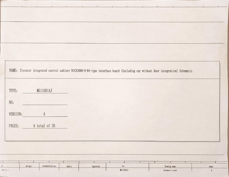
NAME:
Elevator
integrated
control cabinet NICE300-B-B4-type
interface board
(including car without door integration)
Schematic
MGI1001AJ
TYPE:
NO:
A
VERSION:
PAGES:
A
design:
1
m17
A total of
35
standardization:
Audit:
Approved:
no:
MGI1001AJ
Drawing name:
Schematic
cover
page:
A
NICE3000new
1.
electrical schematic process standard:
Power class naming rules:
380V power supply in the main air switch before the
three-phase five-wire named R, S, T, N, PE.
220V
cabinet air switch in the previous stage named Xa, Xb, in the air switch after the
lighting power supply
named
501. 502
stage
Control transformer secondary naming rules AC 220V to 201,202, 110V AC 110,102, DC 110V for the L t.L
24V output named 301,302.
After these naming according to the rules step by step, the range of 103-199,203-299,303-399, 503-599.
2. Line number naming rules:
101-199 as AC safety circuit related line;
201-299 as the control exchange 220V related lines;
301-399 as the DC 24V related lines;
501-599 as the exchange of 220V lighting circuit related lines;
801-810 as lighting 220V AC shaft related lines:
3. Switch and contact rules:
All
4.
switches and relays, contactor
in accordance with the open on and off, left and
right closed habit.
contacts
This schematic applies to my company' s modular one machine control cabinet.
5. Drawings
in
the line number naming method:
Example: TB: 501.TB represents the terminal block TB, 501 for the line nunber.
There are two kinds of TA and TB terminal blocks in this picture.
6 drawings applicable scope:
and no rom
Asynchronous with
computer room
control cabinet. Asynchronous machines do not need to connec
the'synchronous machine increase components and
a
related lines.
design:
0
standardization:
Audit:
Approved:
Figure
MG11001AT
1
9n17
number:
Drawing Name:
Process
standard
page number:
PO4
50
130
9
131A
131A
131
301
133
X4
SGC3
134
EE
Y6
5
OV
1
Y5
Mains fuse
FUSEI
SE2
110
rheel
Side
Orerroltage
protetion cireait
indicatar
Y4
Y3
121
E
1
design:
0
standardization:
Audit:
Approved:
igure number:
MGII0IAJ
Y2
123
a
Y1
speed
D
9017
Shaftsafety
40pin
Drawing Name:
KCB-B4
interface
board
page
layout
PO5
number:
lixite
SUP4
Public end XCOMI
SUP3
02
10Z
adhesion test X28
lock
Door lock adhesion test X27
Security testing X25
AI
control
13
3017
board
Interface
safet
-
VER:0
Star contactor feedback X8
X
Brake contactor feedback
19
DZI
nal cireuit
Synchronousachines have star contactors
board
MCTC-KCB-BA
cable
19
circt
control
cabinet
132
OP
lock
spaE
HCTC-MCB-C3
VER:0
130
door
Xl
Alternate input X3
13
Control
or
30
spare
14
SCC2
B0
Full
tenial
28
CAN2-
Alternate input
SCC3
4
Public side 2 XCM2
CAN2+
CTC-KCB-B4
YER:0
33
34
inc
board
Contactor
Interface
electrical
Door
the
Door lock adhesion test X26
X24
1BI
X23
133
plug7
Check
CN3
SIW
Run contactor feedback X6
XZ
Y5
101
24
20
12
302
Y
1
52
3
relay
OUT6
| 118
Normal position plugin
Ul5
coil
|SI
Bypass start signal
301
CA-
CAN
Iergency
CAN+
CAN+
AN+
ergency
302
02
electric uplinkX
electricdownlink
Energency electric switch
125
14
4
bmergency electric signal X9
301
Control cabinet
energency button
3
Ersy
XI1
iteh
dn
srite
relay
coil
relay
10
5
OUTI
ciertric
relaycoil
operation relay
12
12211
123
10
110
9
elertric
11
T6
CIS
YI
relay
Yl
+24Y
101
co11
2
12 brakerelay 0UT2
K10
contactor control
A
Y3 star relayOUT3
:o echine use
Cabinet aicro svitch
Kun
coill
301
DStar contactor control
DBrakecontactor control
A
DZU
301
Door machine power
Brake power
Note:nomach ineuse
TE3
t
intercon
I
GAD
Brake
301
3
power
MCTC-PCB-2
YER:0
302
9017
design:
o1
L
L
standardization:
Audit:
Approved:
3
2
ZQl+
208
0
N
L
A
box
4202-
202
hervol
DC12
ZMDI
Kh
102
101
Figure
number:
MGI 1001AJ
tag
Circuit
Drawing
Interface board
201
Name:
to the internal viring diagran
10Safety
101
circuit poVer
202 Door brake
Additional
2
201
Door brake
power
brake po
power
page number:
PO6
suppl
suppl
board
BA-hoist cable
MCTC-KCB-BA
VER:0
Rack
u
Shaft safety
Door
31
plug in|
507
121
Fuse
AA
Eeryency
lains power
208
electric
POWI-car lighting
4
131A
ls
d
lock
5
133 6
130
startin
ht
3
PE
|
PE
plug-in
122
4
side
bost
the
vbeel,
band
dise
roon
e
chine
energency
Scc2
6
134
508
braking
supply
cabinet
Control
control
board
MCTC-MCB-C3
VER:0
Additional
signal
ontrol
Interface
16
ing cable
11
2
SGCI
SCC2
Erternal
24Y
porer
sply
24T
porer
Erternal
positive301
supply
CAN comunicat
ion
CAN
stop
On the flat floor
10
302
2
CAN*
negative
3
301
302
CAN coamunication
ergncysta
hand wheel<ch
plug lns
AB-accompany
MCTC-KCB-BA4
YER:0
40Pcable
14
board
braking
stop
SCC3
heel,tne bost
energency
N-nert
host
Additional
DPower
SCC2
121
rooa
2
PR2
oegatire
switch
PI1
re tl
123
is
limit
eed
chia
yarschie
roa
te
chie
X
Under the flat layerX3
cable
plug
Power
12
13
125
1liniter, rope clamp
9
Accompany ing
11
32
SCCl
OS-speed
ing cable
1
207
32
32
ety
Aaccoupady
13
power
Plugins
EMO2
are plug-in
lecs
ctder
Dbackup
PON2
door lock
circait
Interface
CAN+
H CAN
cable
Accompanying
FFLI
plug-ins
eak
102
2
0
DC121
12
re
2X21ire
input
inpu
DZI
Pire input
X21
BB-Outbound
301
301
302
SUPI
MT
10
4854
Al3 485 comunication negative
485
12
0verload
302
302
301
301
BC-pit
interphone
R
Pit
traction nachine contfol
202
relay
De ert
design:
0
1
secord
deceleratia
the
deceleratian
deceleratin
signal
standardization:
2
DLSI3
Under
reduction
DLS24
BD-forced reduction
1
3011
of
deceleration
the
level
X18
signal
017
sigal
sigal
AZ0
0n
feedback
oder
X17
On the level
X14
Audit:
Approved:
of deceleration
On the second
On the second decelerationsignal X16
A
of
lerel
Al
signal
X20LO Overheating feedback
X22 rake feedback 2
X18rake
the
second
/
3
of
deceleration
next
level
52014
The
plug-in
301
302
301
Under
lated
cable
BE-forced reduction
1 301
brake
intercom
DC124
OUT4
coil
301
Host
Outgoing co0munication cable
KOD-
svitch
F
load
1
X12MOOa
overload
signal
Koonfull
Figure
number:
MGI100IAJ
decelerati0n
Drawing
I
Interface
board
302
sigia
On
the
reduction
s1gnauULS24
page number:
Name:
external
2
ULSI3
wiring
diagran
PO7
suitch
0om
is
1
2
KOD+
485 comunication
X13
14
comnication
forced
plug-ins
13
çable
force
ire
40P
Safety
Host
VES-
|
wheel
switch
emergency
MES
F07
Short
Pit
circuit
this
Break rope switch
Car
top
circuit
electric
TNTK-1
Safety
SUS
without
this
function
switch
3
--
electrical
Short
instructions
Speed
circuit
vithout
this
Buffer2
BF$2
131A
door
lock
J3IB
electric
130
linkag
120
Control
&
121A
am
switch
esie
L
132
sritch
Electrical
-
function
this
ble
BUr,
board
KCTC-WCB-C3
Public
circuit
n
plag
Front
Under the linit
FLSD
FLSU
15325
-
f
TB126
end
XCMI
Security testing
Door lock
detection
BA-
SV1tCn
2
The linit
121
vithout
Short
the
1ocK
SUPO 129
instructions
lock
SUP130
sored
door
2
mety
Rail
SUP2
circuit
switch
0S
function
is
car
mith
ltate
Safety
liniter
Electrical
switth
cact
I
1
operation
122
Door
Buffer
BISI
118
A
128
button
PO
Energency
maintenance
Safety, circuit
stop
box
12A
124
emergency
repair
emergency
61S
l10A
Car top
functionp;+
Pit
button
T
Short
without
box
sitch
Electrical
185Y28 Door
Sungle
door
lock
tection
short
ergency buttom
1
Al-f06,
button
instructions
circuit
connector
emergency
Dischand
cable
cabinet
travel
Control
133
K7
S2-P0
130
S2-POS
dcr
detectiam
134121ser
P1O
loc
UCMP
--
132
3
STnchronous nachines have star contactors increased
102KCOM2
Sl
$2 are
door locks. Fhen the elevator is in noraal use, the plug is inserted into the SI socket. Then the hall door lock is locked, the plug is inserted into the 4 pins above $2. hen
bypassing the car door lock, Plug into the
ote1:
and
by pass
hould be feet.
ote
control
test, please disconnect the 40pin cable between the interface board and the ain control board to avoid danaging the inverter ain control board during the voltage test.
2: Then the
cabinet vithstand voltage
ote
UCWP plugs need to be unplugged vhen testing UCLP functions for on-site testing of
functions;
bottaon
of
the $2
Ceck
the
SCB-AI
publicend
4
3:
P
L
A
9017
design:
0
1
standardization:
Audit:
Approved:
igure number:
MGI1001AJ
Drawing Nane:
Svnchronous
zachine single-door safety circuit
page
diaran
PO8
number:
MCTC-SCB-AI
Control
Interface
board
board
CTC-KCB-B4
VER:0
MCTC-KCB-B4
VER:0
301
0
D
24
3-01
K7-01
302
302
:
FLI
hooe area
1AB-PO7
40P cable
LZ
llone
D12:
area
nert door area
AB-P10
X
in
5
advance OUT5
coil
Y5 open the door
relay
Next door area X3
K7-12
Door zone signal input
K7-05
Z
06
Door zone
Closed door output feedback X19
signal input uLl
SAL
SXZ
K707
Closed door output feedback X19
Safety
101
D-
circuit
_-1MF0
Front car door
S1
svitch
lock
j3
A-P5
i
131AID
UCMP test used
h
UCIP
13
BA-PO4
Front door lock svitch
131
DS
30
132
BA-RB6
-E7
PO8
A-06
D
2
design:
0
1
9017
standardization:
Audit:
Approved:
Figure number:
KGI 1001AJ
Drawing
Name:
Sunchrannne cinmlo-dnr TrUD
oohamatio
page
nunber:
PO9
diamam
1
instructions
Short
Break rope
button
operation
18
3
Safety
rope
- 12122
Electrical
lock electric
131B
Swi
nDS
linkage
tch
Rear
door
lock
n13-
switch
ni
sged
the
5X25
s
183
Short
Sirgle
door lock
Note:When
S02
single door, S03,
SCB-D
1: SI
and S2 are
When
the control
3:
UCHP
plugs
ote
ote
door
by pass
2:
need
cabinet
to be
locks.
vithstand
unplugged
design:
9017
0
1
When
the elevator
voltage
when
testing
test,
UCKP
is in normal
please
disconnect
functions
standardization:
use,
the plug
the 40pin
for on-site
testing
Audit:
is inserted
cable
of
between
UCMP
into
S4
2
SO3
the Sl
the interface
socket.
board
When
and
the hall
the nain
door
lock
control
is
board
XCMI
Security testing
lock
detection|
by
AA
detection
plg
-
y28 Doar lock
PI4
itti
134 X27
S2-F5
S2-P04
-----
end
Dtrial
Public
L
KY-P10
board
linite
121A)
BA-PR
-POG
is not vired
Synchronous
nachines hare star contactors încreased
L3 44
BY
-
locked,
to avoid
102XCOM2
the plug
damaging
is inserted
into
the inverter
the
main
1/2 of
control
$2,
board
and when
during
the
car door
the voltage
is bypassed,
Cock
Insert
to
pblie
$2's
2,3 feet.
test.
functions;
Approved:
igure number:
MGI 100IAJ
2
BSZ
26
132n
132A
Buffer
3
Door
130n
linkage
electrical
2DS
linit
page nunber:
Drawing Nane:
uchine doubledoor safety
diagra
P10
end
Front
door
the
FLSD
MCTC-HOB-
cahle
131A
|
130P-0
Under
120L
AA
S129S
limit
FLSU
Control
aiat
121B
Po6,
switch
SUPI
function
cireuit
lock
Rail lock
this
wben
doar
vithout
The
2.
accopenied
1 car
SUP2
cireuit
contact
Door
Short
2
B+P08
UZI
function
121
doar
tate
stop
this
121A
door
emergency
top
ithout
sriteh
Car
circuit
szfery
Short
Switch
Sbort
-
limiter
switech
Blectrical
functico
switch
instructions
cirCuit
2
Speed
single
electrical
BFST
14
instructions
2
switch
Buffer
B-P7,
circuit
this
Safety
CIS
Clamps
Safety
--
button
electric
.
---
12
ergency
cable
maintenance
top
T
eratim
eletrit
then
Car
124
crgeacy
_
needed
box
GTSI
N12A
LIOA
function
Pit repair
emergency
GIS
PU-PO5
acrease
switcku
this
the
emergency
MES
without
plag
Electrical
circuit
box
Doaor
Pit switch
Switch
the
wheel
vithout
hand
an
energencybutton
|
emergency
Disc
svitch
button
cireuit
Host
cabinet
sorted
Control
car
cirçuit
Syachrenous
lote
Safety
wheel
Shorted vithout this function
operation
indication3
Safety
Rope
clamp
this
Electricalsviteh
SUPL
129 SIRIP2
77T
L.
120
1214
132n
Shortedrithoutthis
side
board
1XCH1
-J
function
loX25
=
ns
-PO8
L31 26
--
652
K7-P16
testing
plug
27 r
A-PI14
n orting
Safety
85 28Dr
AM-P06,
RA-705
Door 2 car door lock svitch Singledoor vith
133
_
control
OS1
sviteh
electrical
lock
Rear
US
132A-
2
B$2
MCTC-MCB-C3
Public
130SUPRo
130
Buffer
P
19N
Main
121B
linkage
318
Lower
linit
FLSD
function
Sritch
lock
Front
131
2
Upper linit
FLSU
121A121_I-
sviteh
without
Electrical svitch
Rail lock
ISP
indication
circuit
liniter
Speed
svitch
Shorted
SUP2
131A
Sritch
1
CarDoarLoct
Backrp
Car top emergency stop
Doar
plierselectrical
1
BESI
118
_12122
14
Buffer
detectian
Safety
circuit
button
sbert
13
126
linkage
L
T
electrical
top orerhaul
TCD
Safety
dorn button
box
emergency
PESI
detuctim
top
Lar
Pit repair
switch
door
Car
C
tensioner
rope
Ioct
14
electric
Emergency
overhaul
limi ter
Broken
13
4
13
124A
3
safety
126
top
124
ICIB
Speed
S Car
button
Car top up
box
button
emergency
siart
beeded
then
ncroase
running button
top
Car
Pit switch
switch
ocer
Plate
Electrical
MES-2
Iuct
Ieergency button
MES-1
cable
Hosts
but ton
1
sritch
cabinet
indication
door
Control
emergency
circuit
Eletrical
Safety
iSAI
increase
-
easeu
nen toe5Conodshine has a
can
tactar
ne
1
SCS1
clcsed
laiià2|kriliay ioar
Se2
star
ir
sritch
Drhle doer ziliy
loct
caected
1SA2
A
BY
102KOOM2
Detectian common
LOP
Lest
S06
u
Additional
te 1: S1 and $2 are bypass door lock plugs. Fhen the elevator is in normal use,
te 2: When
the control
te 3: When testing
the
cabinet vithstands
UCP
0
1
design:
9017
the plug is inserted into the
voltage test, disconnect the 40-pin cable between
function, UCKP plug combination
needs to be pulled out for UCkP
standardization:
brake control
Audit:
Sl
the interface board
signal
socket. When the bypass room door is locked, the plug is inserted into 1/2 pin of $2. Then the bypass car door is locked,
and the main control board
to avoid
damaging the main control board
of
the plug Plug in the 2 and
3feet
of S2.
the inverter during the vithstand
vol tage test.
function field test;
Drawing
MGL 1001AJ
number:
Draving Name:
muchinevith
Asynchrocous
Qu Depu
OP safety
page number:
loop
diagra
P1l
Control board
CTC-SCB-D
Interface board
MCTC-HCB-C3
MCTC-KCB-B4
301
K7-O1
K3-01
2AV
302
302
OCOM
7-02
FLL
FL1:
40
cable
2
Home area
hoee area
PO7
OFLI
K7-03
FL2
next door area
AB-P1O
OFLZ
7-04
XI
Next door areaX3
Y5 control OUT5
5
relay coil
K712
K705
OSY
Door zone signal input X2
SXZ
K707
Closed door output feedback X19
Safety cireuit
101
D
CSL
L 130
UOMP
1AAM-PO5
Front car door lock svitch
plug
131A
2
UP-POL
JL-O
Front door lock
witech
P2
130
12- PO4
132
31
Single-door shorted
UCMP
When
SOI
K7-08
tB-PO6
door
test
Rear
used
132
SOZ
K7-10
lock switch
33
BA-PO8
svitch
Rear
loch
A-PO6
cardoor
134
133
dor
Ater uiliay
SCC2
lac
SCC2
auxiliary
door
SS
lock
S05
KT-P13
AB-P02
Pront
S04
K-09
AA-PI4
AB-POL
SCC3
SALLUOIP-PO3
KT-P4
SCC3TOIP-PO4
S06
A
9017
design:
0
1
standardization:
Audit:
Approved:
Figure number:
G1 1001AJ
Drawing
Svnchronous
dual-door
page
Nane:
ICMP
schematic
diagram
P12
number:
Main
control
board
Interface
MCB-C3
301
302
40P
D
D
301
FLI:
cable
Hone Area
The
302
302
K3-02
K7-02
AB-PO7
lover door area
OFLI
F12
K7-04
AB-P10H
XI
Lover door area X3
Y5 control
2AY
k3-01
FZ:
Hone area
MCTC-SCB-D
board
MCTC-KCB-BA
UT5
18
Y5
relay coil
K712
Gate signal input
2
22
K705
SXI
K7H06
X7H07
Sealed door output feedback XI9
Safety
V
-
101
130UCPplugI
Front
OSXZ
circuit
car door
lock
130,
131A AA-PO5
J
switch
131AUOP-POl
13-UMPPO2
Short when single door
K7-08
132
T32
131
Rear door lock switch
used
BA-P07
132
I
hen
UL
KT-10
BA-PO6
UCMP test
|
30
BA-PO4
Front door lock SKILCD
RA-PO8door
lock
Rear
car
U5
A-PO6
svi tch
GS2,
-
derled
Rearlary
134
134
A-P14
SGC2
SGS2,
door
auriliary
Front
SAB-P02
loc
Sudl
05
K7-P13
K7-P14
LS
SLUOMP-PO3
a
LKZ-O1
Catrel
Z20YAC
poer
SEC3
a
SCC3
SGCI
UIP-PO4
s 2
S05
ba
QX-240EU
a-
2I2SO6
i
standardization:
Audit
Approval:
Drawing
MG1 1001AJ
1
0
number:
page
Drawing Name:
Asmehronous
kchine IDP Sehotic
The
Oedo
design:
9017
Plan
P13
number:
Synchronous machines have star contactorsincreaser
Star contactors
QF main
epmty
o
LID
NICE3000
notor
Main
L2
power
L3
electric
Overhaul
uplink
Maintenance
down
blac
(PB)
signal
input
signal
input
signal
input
downl
Slow
down
131
X26
Slow
down
testing
Slow
X25
ty
XO
133
27
6a
134
X28
102
C
test
svitch detection
Closed
ERN1387
ERN1387
(Cable
encoder
encoder
port
le &etim
toer
purple
I
I6
17
I18
I19
t20
18
door output feedback 19
Hotor bverheat
Fire
Brake
diagran
switch
linkage
detection
121
2 122
H2
o-
o
24Y
COM
inerese
catactara
input
load
Slow
down
down
1
Slow
Slow
down
2
svitch
board
Interface
MCTC-KCB-B4
2
detectim
ba penig
bec
linkage
rake
svitch
rese
en te
detection2
AsynchranoAS
achine
full
down
21
o
input
input
signal
down
Slow
rake
signal
signal
overload
Cleedd
otar
protection 120
facing up)
port
o-
2 16
2 17
Adhesiont
2ella
o
u
I15
x4t
15
uplink
Maintenance
Roon
us Room
check
power
Overhaul
i
2
test
Brake
1O
X12
x13 o-
load
down
130
Adhesion
pit
full
Slow
detection
9Emergency
oX1
o-
102
7b
gray
Brake detection
uo
overload
n
the test
24Y
10C
M)
b
blne
5
Securi
CM
Run
Star
9
blac
Room
Roon
7
spare
switch
leveling
signal
adrance
4b red
yell
15
16
Brake detection
Star detection
Emergency
4a black
grem
X5
X6
the
Bypass
in
o()
spare
the test
4
aodule
Run
Under
o-
signal
orerbes
Bypass
mchies
1leveling switch
the
the
switch
wtor
Under
level
creese
use
the
Door area
1
brake
On
12
protection
and door
o
CUN
A
circuit
D
a
mir
er
o
3-
area
averhent
Control
da
io
switch
Door
Fire
the level
1
alaet
catral
te
iside
istalled
ls
Iscaie
On
L
PE
the contactor
str
Run
Srehraces
N
encoder
Braking resistor
and
terainal
fai
Y2
test
energendy
Brake
input
of PC-D
CNI port
Note
2:
and PG-E
of PG-D
is connected
and PG-E
Asynchronous
machine
adapter
PG-D and
of
WCB-C3
port,
HCTC-PC-A2
Brake
above
Star
contactors
the
main
control
specification
ARD
board
4
Fire
is DB15
female
Closed
is repeated,
output
need
to find the input
door
Y5
Closed door relay
relay
point again.
Y6
if the function
Fire
output
port
PG card;
Note 3: X23, 124 input port can only be used for one function,
ynchronous achine increases
Star contactors
PE PG cards
of
contactor
Y3
Increasewith
signal
to J12
is encoder
to
contactor
spare
9017
1
design:
0
standardization:_
Audit:
Approved:
Figure
number:
MGI 1001AJ
spare
Drawing Name:
page
ain
P14
cirenit
diaoran
number:
adronce
45kw
X23
open
in
unit
X24 Master
I
J1
The synchronous machine can be adapted
1:
Note
the contactor
Run
yI
o
Braking
Run theco0
tactor
o
modle
J
Analog
PE
card
the
PG
CA
CAK-
apening
type
A*
CAN
vben
use CTC-PC-A2
o CAN+
o AI Analog input
O M
comon
BR
Iocrease
nachine
DBR
u it
Rraking
9
MOD+C
o CAN-
MDBU
O
Inverter
Asynchronous
P+¢
lure
PCA
+)
Porcr
+)0
control
switch
protection
transformer
OFBI (24)
TRF
QF main
|
empty
220VAC
l10VAC
LI
O
OY
8
User
to
no roon
-
Leakage
distribution
install
and
box
control
switch
protection
QFB2 (6A)
K5/8
Interface
cabinet
K5/7
board
ACI10Y safety circuit
MCTC-K
101
VER:0
AAL
cirait
parvtect
the
102
208
207
9-H208
1
Door
machine
-207
K6/1K6/2
Interface
board
MCTC-KCB-B4
VER:0
Host
FE
MCTC-PCB-A2
Brake power board
Run the contactor Brake
B
K6/3
VT/5
54
7A
110YDC
K6/4
0X3
Control
Note
Corresponding
Note
3:
2.4
1,
200VDC,
cabinet
Phen the
The
brake voltage
MCTC-PCB-A2
default
output
5 in the
and
the renaining
OFF
0
1
of
voltage
NICE-C-PS1
position).
DIP are
configured
porer board
to the short-circuit
design:
o017
brake
drop
brake
hen
J3
according
is
on,
function;
power
the brake
bor
power
to
customer's
using
is 110VDC
supply
the
(the
function
buck
DIP
is 200VDC,
coil
BM
Z02
302
301
24VDC
order;
the voltage-dropping
when
o
IK3/1
K3/L
24Y
2:
KT/10
K3/2
COM
Note
brake
contactor
L+
1:
e:
Leakage
AC110V
function,
switch
the
on
is not used
CN2
output
the power
DIP Switch
on
and 12
is invalid;
DC110V
over
board
in
the power
the
box
supply
is at
board
J3
when
3s after
does
the output
ON
not perforn
of
buck
circuit,
12
is iplenented
value;
the renaining
position,
in the
short
any
J2 selected
box vill
be
set to
1
and
2, respectively.
OFF position;
standardization:
Audit:
Approved:
Figure
number:
HGI 100IAJ
Draving
Nane:
Power supoly circuit and brake circuit diaaran
page
P15
number:
powe
Car top
maintenance
one plate
Car top
24V 6PO
-Dc24Y
knob
TO
Car
button
public
access
er
top
58
top
X12
maintenance
signal
aintenance up button
TQIU
TCIB
5-U
Car top down
55
X13 maintenance
up
button
TCID
56
-OX14maintenance
Tb-PU
down
CAN comunication
Control
24Y
T
Energency
Bypass
statt
K4-PO4
Public
bypass
start
signal
SI
stat
switch
60
board
DC24
X4
electric
CIS
K4-PO1
link
Bypass
X9 energency electric signal
button
Eamergency
electric
CIU
upward
T
button
55
03
X10
Energency electric
button
emorgency
clectricuplink
down
56
K4-P02
Xl
energencyelectricdomlink
Note:
1, car
top
repair
2, maintenance
3, after
Car
and pit repair
speed
the bypass
top sound
and
circuit,
and emergency
device
is started,
light alara
device
design:
n17
at
electric
the
starts,
the
same
running
engine
tine
speed
room
the output
through
the
car top
enters
sound
standardization:
communication
to meet
to distinguish,
the
energency
and
light
the national
and outbound
electric
running
state;
car top
alarn signal:
for warning
Audit:
communication
to the
system;
standard;
and
Approved:
car;
Figure
number:
MG11001AJ
Drawing
lverhanl
page number:
Name:
cirnit
diaram
Pl6
|
207
D
24Y
7
FL2
10
L
2A301
COL30212
Doar
FLI
Overloed
algral
panel
Sigmal
Full
3015
LIht
sipal
R
2
BI
HOD+
TBI
5
Hone area photoelectricPY
FL2
Lorerdocr
DOBIDI2
DCBI DII
COM
12
1
301
tnl
e
ricti=
|3
XIl
3022
On
X9
DP
photoelectrie(
4
X10
Lhder
10 301
1
301
DP
301
14
the
9
301 1
302 2
photoelectrle
Closed
Open
analog veighing viting
4
inputAI
TAL
3
B3
B2 14
order
7
close
order
302
MOD-
Forced
6
to
the
box
Analog
RDZ
CLI
X5
3022
/3
machine
N
301
Close
control
inplace
the
Main
DC12
door
8
201
5
WoPront
3
PE
3 302
4
COY
DENI
e t r epharX3
L
LRX
porer
DCI
207 6
COBI
4
X7
2412
301
302 L
208
13
sigralX8
X1512
use
2
6
301
are
24Y
302
EDP
touch
1
curtain
5
CAN+
CAN-16
door
301
LIght
CAN
CO
301|4
1AL10
ront
CC
PE
SL
3031
302 14
08
PE
PE B
30113
flat
2071
Sound and light alarm
output
CB
gDP1
the
VER:0
interface
board
load
top
curtaln
220V
Car
flat
MCTC-CTB-H3
A
ptotoelectric
EDP2
Y4
20717
1
signsi
panel
use
24Y
porer
curtaln
Car
o-Back door
IES
machine
s
8
7
X6
close
Car
OL12
Open the order
C3 13
C2 14
C115
LCM
2
TB3
CL12
Car
top maintenance
TRBI
TAI
30116
2
Close the order|
13
top
DEN2
pX4
place
toar
te
fn
tya
X12
up
aintenance up but
Maintenance
down
Car top
button
access public
2
Car
DI1
COM
aintenance
TCIB
X1312
DOB2DI2
DCB2
top
TCIU
Maintenance
14
3
Car
3
top down
4
button
TCID
X14|1
L
design:
standardization:
Audit
Approved;
Figure number:
Drawing
Name:
but
up
13 14
2AN01A
PE
19
button
knob
Light
curtain
PE
|10 301
top run
TCIB
top energency stop
20813
301
top
TCIU
. TCID
Car
Y4
6
207
22
Car
DC2
8 MOD+
9
21
30211
302
HOD-
naintenance
126
ton
6
1
6
Light
DC12
Cloxed
box
5
1246
EDP
X16 12
301 5
to
control
Z01J
COM
30114
X2 10
301
302
Forced
Vice
2
top,
CarCL
PE
Backdoor
1R
2
4
Car
PE
COB2
3
12518
touch
208
page
n
nunmber:
Car
top
integratedinterfaceboard
Car top integrated interface board
SLI2
SL/
owtpt
CB-P03 -10mdand
301
alern
302
1lsht
CB-PO4
303
Sound
BZ
and
1ight
alarn
device
CA
131A
Y2/1
507
|5
133
6
134
1o
125
L1
/
123
|13
123
508
Y2/4
SOS
124
A-16
Y EJK4-fan
6
4
PANV/3
24
Car inside the
Accoapanying cabl
507
125
fan
Repair
handle loop
5
127
FAN/7
relay
Safety gear switch
3
|/5
Y2/3
508
2
509
ISC
FANA
127 12
Car interior lighting|
lighting
relay
Security box Speeding protection
128 Lo
FAN/&
510
SUP2
Y3/8
2
128
Car
Y3/2
top
socket AC220V
Alternate safety switch 2
SU
129
-
TURI
SUPI
Y3/1
Rail lock
1292
COBI
COB2
130
Car
top
GS1
lighting switch
Interface
Comunication
131A
Car display panel
|
2
130
485
SUPI
1
Front
car door lock
SGC
SCC1
27
SGSI_
Vice
lock contact
SGS2
+24Y
485
ICHT
LICH
laterfca
Car COB board
Commlaln
2
SC21
FAN
gting
control
3
After
Fan control
133
|2
the car ldoor lock
GC2
134
Overload indicato
HCB
Cascade expansion
design:
standardization:
Audit:
Approved:
Figure
number:
Drawing Name:
page
number:
Call button
ahade
cellg
1shtlng
ad
ergency
llehttng
alntesace
taop
TECL
Car
Pit interCom
Moni toring roon intercom
Car
interc0
Alarm bell button
800.5
FRIE
station
52
611
507
Call button
EEEEEL
2
GND
Call button
FAN
PE
2
Voice station
Room intercon
CB-PI
AB-P
TEL3-4
C8-Pl
AB-PIR
TEL3-P02
AB-P1
TEL3-PQ
AB-PO4
TEL3-PO8
DC12Y
|508
4608
5
CB-P12
Car inside the
fan6
7509
8 510
+24Y
1
LICHT
CB-PO4
Car
l
OV
3u
Car eergency
top intercon
TELL
control
FAN
Call button
K9
DC12
DC12Y
lighting
ND
COBI
GND
Call button
R
Y2
4
5
DC12
508
B02
302
Power
Z01
DC
UZ
302
ZO1
Suppl
UZ
crgency
Noice
S0Z
MOD-
7
8
MOD-
07
MOD+
9
301
10
301
Z01
MCTC-COB-A1
507
MCTC-CTB-HI
Car interface board
Instruction distribution board
Car
top socket AC20V
b08
design:
standardization:
Audit:
Approved:
Pigure number:
Drawing
Name:
page number:
board
-0-0t0
-CCB
Instruction distribution board
JPz5
0M
MOD-
MCTC-COB-AI
JP20
Direct drive button
communication
485
JP25
N
MCTC-COB
Instruction distribution
NSB
board
JP20
485 conmunication
MOOLED
Overload indicator
Overload indicator
Driver button
HCB
JP21
JP21
HCB
ATS
LED
LED
CBL6
CBOI
JPI
JP
1
layer button
layer button
1
Cormutation button
JP22
P22
ACB
LED
LED
CB16
JP2
2-1evel button
2-1evel button
CBO2
JP23
Independent run button JP23
ISS
LED
JP24
Fireman
run
button JP24
FIRS2
ED
LED
24Y
CB16
16 layer button
JPI6
-
LIGHT
JP27
DOB
FAN
124Y
2Ighting control
Fan
control
3
DLighting
D
16 layer button
CB16
P
BOB
JPI7
DCB
JP18
fan control
LCD
(+)
201
LED
COM
ECL Car emergency lighting
Open the button
Open the button
JP17
ED
LED
DCB
Close button
DC12Y
Close button
JP18
GND
Main control box
Car
intercoa
JP28
ED
LED
JP19
Open delay button
Vice control box
design:
JP19
Enternal
sound
DDCB
DDCB
Open
interface
Car top
buttonVoice
deley
standardization:
station
Y2
Audit:
890.6
Approved:
Figure number:
Drawing Name:
page
number:
Leakage
protection
switch
POW1-P02
2 502
4
LI-
IPOW1-PO1
501
AA-P16
-FU2
AA-PO8
507
CA-Pl6
Car
CA-P08
507
inside
-Car
A04
ARA510
ar
interior
lighting
|
----socket AC220V
top
switch
fatercal
bor
ainterazce
cireult
ligiting
--
cireult
lighting
top
Cer
lighting
top
switch
zalaterazce
Car
micro
Car
Illuminated
Leakage
protection
4-ed
liçhtizg
saiatenace
Car
----512
tap
top
S
the fan
marqey Ibtlq
*
switch
QFB4
802
802LIHO
802
lightihg
indicator
801
C
Shaft
Shaft
lighting
LIHI
Shaft lighting
Shaft
21
Shaft
{
2
lighting
3
3
-
LIHSI
CIH-PO3
B01
CIH-R4
lighting
PLI
IH36ting
805
iPit lighting
LIH-PO2
switch
lighting
socket
Hoistway
LIHn
LIH2
803
804
803
-
Shaft
lighting
distribution
box
design:
Note:
no room
to install
standardization:
and control
2
B04 LIHR04
N
User
switch
LIH-PQ
12
Pit repair
box
cabinet
Audit:
Approved:
Figure number:
Drawing Name
page nunber:
no1
Engine
room
switch
lighting
oo
Rooa
C12/D
110
intercoa
Brake
feedback
1
2
orerheating
feedback
Brake
Motor
feedback
Speed
liniter
Dischand wheel
Brakepover
design:
standardization:
Audit:
Approved:
Figure
nunber:
Drawing
Name:
page
number:
NICE3000
U
PE
-P03
HR-P02
11
110
121
L
MES-2
Motor
Disc hand wheel
design:
0S-PO5
OS-PO3
122
L
Speed liniter
standardization:
NT-PO6
|
201
Integrated
control
NT-P1O
MT-P02NT-PO3
z02-
MT-PO1
X18
X22
cabinet
MT-PO6
X22
30
PC-E
DBl5
T
iost encoder
Brake power
Audit:
Brake check switch
Approved:
Figure number:
Drawing Name:
page
number:
LO
L
design:
standardization:
Audit:
Approved:
Figure
number:
Drawing Name:
page
nunber:
Control
Note
cabinet
1:
CA,
Backdoor
light
CB
curtain
Vice control bo
Rear
door
machine
power
Car top maintenance
box
==
Rear door echine sinal cable
Main
control
After the car doar lock
Carpet
plugin
Auriliery door lock
SOSDZRDZ
FAN
SUP1/2
DCI
DP
DENI
wT/2
S1SL
EDPI
2: Asynchronous
Note
3: Additional
a
backdoor
machine
safety
S1gnal
ucha
switch
bu
ar
alara
r
Audibla
Door
door
Flet layer
ourtala
Saelyse
increase;
A
design:
ta
area
inaria giniu
L-J
increases
switches
r
Light
Btandby switch
increase
loc
Note
is
Yelghing
1: There
orerhuastlag
Note
/
E3:
standardization:
Audit:
Approved:
Pigure
M1001
nunber:
:
Drawing Name
page nunber:
bo
Control
cabinet
BA BB BC
L
DA
DB
DA
Pit
interco
1
DC12
2
|3
R
804
3
nsioner
T2
PE
Pit
19
repair
box
Cmergency
button
56
L
2
ffer
-
Pit lighting
803
GND
PESI
PE
switch
111
PTI
6122
emergency
11
PESZ
button
Pit energency
stop
box
112
PT25
6
113
Pit repair
box
Pit repair box insert
119
2
118
LIH
Pit switch box insert
802
B03
805
805
803
PT
3
804
P12
6
PE
PE
805
PT1
804
112
5
111
111
803
119
804
PE
118
6
112
PE
111
113
112
DA
B01
302 (CND)
DB
10
MOD+
L
MOD
DC12
12
design:
standardization:
Audit:
Approved:
Figure
number:
Drawing Name:
page
nunber:
Car
Cu
design:
standardization:
control
rlae
ba
Audit:
ala
cable
lnFL
u302
Approved:
(vea
xaz
Figure
A
number:
N
ge
Car
rafnterance
EN
top
EEN
pomr
curtaln
1ight
sAch[ne
door
door
Pront
door
Back
supply
pOwor
curtain
11ght
Backdoor
door
Back
slnal
door
Pront
slgnal
door
Front
protectlon
Onm
243,
t
doer
the
elo
Safety
electricity)
cable
N
(strong
N
ooo
Borwter
ing
siteh
theral
alara
light
and
K2-sound
4-fen
Flat
valkle
talkle
508|512|
Accoapany
larn
stlteh
Lng
Felghlog
K9-lIght
l11ht
sltea
301|sz2
Acconpanying
relghing
Analog
top
Car
coenlcatloa
bes
Bypass
201
302
cantrel
lte
fan
Car
comualcatloo
11shting
Cardoe
1645
V2R:A00
KCTC-CTB--3
BAR
COE
INNN
NDIJ
302c12
PE
l2
EN
nu
251,Omm
Drawing Name:
page number:
outagc
omorgoncy
Elovntor control cnb
loveling dovicc
inot
ARD power
NICE3000
KCTC-ARD-C
main open
power
QF
Enter
power cable
the
Ll-
power cable
S
L2
12
o13
-
63
8
PE
PE
-LJ64
oT
N
PE
PE
-oDI3
14
The main
Distribution
Qutput
R
air
--o,COM
open
tgst signa
boOx
AC220V
Door machine
brake input electrici
K7
+-+
Y1ot
Eimorgency
loval im
sighal
SUP4-2
SUP4-1
SUPR2
SUP3-1
M1ot
Note
1: This
Note
2: The energency
The
Note
risk
A
danage
3: The nain
Increase
Note
of
power
the main
4: Controller
circuit
to
power
is suitable
poxer
supply
the control
supply
of
air cut open
power
failure
for
must
the control
be ARD
vith
cabinet
vith
ARD
380V
threr-phase
energency
leveling
and
tworphase
4-level
nain
input
X?
X23
301
device;
220
othervise,
output;
there
will
be
cabinet;
the engine
detection
emergency
design:
2
room
contact,
input
must
be
contact
signal
configured
signal
to
with
the ARD device
is reconmended
standardization:
to
use X23,
Audit:
DI3
air switch.
signal
set F5-23
When
input
contiguring
the ARD
funetion,
point;
= 27;
Approved:
Pigure
number:
Drawing
Name:
page
nunber:
User power
Car lighting leakage protection switch
QFB3
Car lighting
switch
leakage protection
QFB4
6A Leakage current 30mA
S|
10A leakage current 30nA
ARD fashion
power main
F
open
FE
E
Trip detection switch
801
B02
|
Distribution box plug-ins
801
Shaft lighting indicator
JoM
M
NC
Shaft lighting switch
804
803
PORI-PO1
POW1-PO3
502
501
CIH-PO1
802
1
LIHSI
NO
CIH-P02
CIH-PO3
CIH-PO4
805
803
804
CIH-PO5
PE
CIH-PO66
1,
Note:
the distributionbox tain opening standard vith
15,18.5
KW when
2, the
system
3, Car
lighting
vith
the air switch
ARD when
4P
svitch, inverter
is 63A;
22KW
the air switch
with
above
a
trip
with
vhen the air svitch is 40k, inverter
1KW
fixed;
detection
switch;
AMP-480701
4, distribution
3P AMP plug-in,
box with
hoist
the shaft
lighting
lighting
design:
6P AMP
work
350536
P-480705
350536
plug-in;
indicator.
standardization:
Audit:
Approved:
Figure number:
Drawing
Name:
page
number:
P25
Flat
layer
Red301
8 10Onm
itch
switch
Flat photoelectric
Magnetic
stripe
magnetic
Red
plate
signal
output
layer
magnetic
10
8
Pitch
Black
302
Black
Magnetic
plate
signal
output
stripe
Ngrade
S
red
grade
white
suitc
teret
Upper
SDleck
DL
PS
signal
Red 301
301
White
Flat
aCK Output
suile mi
Pei
cutting
DZ
red
black
5667-4R-210
5656-T
5557-4R-210
5556
5557-4R-210
5556-
RYV4&0.75
RYV40.75
302
30
PX
Fu'TK
Flatten again
HFlatten
again/FLI
red
RDZ
5557-4R-210 5556-
RVV4s0.75
60
agnetic
301
eeri
Flatten
/FL2
tETet STItcT
UPper
installation
301
black
7
black
Note:
1,
switch
again
30Z
PX
Photoelectric
RYY4*0.75
Flatten
FL2TTK
again
centerline
stripe
the upper
2,
the upper
3,
the flat
4,
flat-layer
method
and
lower
and lower
layer
leveling
level
switch
for
switch
switch
center
center
to the magnetic
distance
the photoelectric
swritch for the slot-shaped
agnetic
between
latetwodista ce
60
a
between
l5m;
20
8Onmn;
switch
at
distance
switch
at intervals
of not
of
less
nagnetie
than
plate
26m
deep
insertion
into
depth
to
the botton
of
the botton
of the switch slot 8an
the switch
slot
is not
small
10a,
&am;
or
to the nagnetic
switch
standar
Chi line
(This chart
by Huitong,
other brands
refer to the corresponding
wanual)
5, nagnetic
6,
with
Ensure
a
plate
pen-type
that
before
around,
magnetic
the magnetic
and after
switch,
switch
spacing
7,pen-type magnetic switch for V
design:
standardization:
Audit:
Approved:
the verticality
the distance
of not
between
less
than
of
t
nagnetic
Pen-type
2an;
and magnetic
stripe
in
6
10mm,
magnet ic
switch
and
nagnetic
nagnetic
switch
switch
in and
out
installation
of the distance
2am belor
Gnn;
afull range
1, 76n/8,photoelectric switch for
Figure number:
Drawing Name:
page
number:
Car
Car chassis
chassis
Induction
OL
Full
overload,
load, FU
nagnet
Inductive
side
(with_parking
proxini
ty
down)
switch
COX
Full load often
open
NO
O
Normally open
Normally closed|
Overload often
close
O
full
switch
end,
load
1stalled
O
O
OL
301
Car at the
COM
NO
NC
301
security
way
304
301
21
JOL_
5557-4R-210
TI
5557-4R-210
Car at the end,
5556-T
211
Installed
Electronic
Induction
Overload,
Rope
plate
ains
switch security|
super
magnet
(vith parking
side
weighing
full
load switch
security
way
switch
Mechanical
Switch
weighing
switc
down)
Overload nonally
O
closed
Normally closed
COM
Installed
NO
way
O
NC
301
SUPI
5557-4R-210
556-1
OL
Note:
21
3020
1, the normal
SUP1
5557-4R-210 5556-T
43
switch
light
does not
2, when the switch work close
Light
shine;
to open action
is on
Rope
21
design:_
board
overload
switch
installed
the way
standardization:
Audit:
Approved:
igure
number:
Drawing Name:
page
number:
the
Swipe
card
MCIC-COB-A1
Instruction
distribution
board
cable
ain
F
JT-04D
controller
COB
Instruction
distribution
board
JP20
485
MOD
I
24-
L24V
QUTl
CTi OuUT2
Overload indicator
HCB
OUT2
conmunication
JP21
MCTC-IC-A
LED
IC card nanager
DI
JP22
24V
Connect
to
COM
LED
--O
the display board Pover:
CB2
JP23
MCTC-ICIC
card reader
Through the door with
IC
card control box
JP2A
LED
Bus-based
IC card
management
-
system
JPI6
CB16
JPTT
Description:
1,
Description:
the call
controller,
(integrated
Sw2 is
MCTC-IC-A
McicGIC-GI
function,
ON
IC
svitch,
the corresponding
be
bit
function
is as
followS:
resetto ensurethat the syste
autonatically
board,
KCTC-1C-GI
antenna
plus
default
hen
used
PI8
setting).
(integrated
password
control
2:
work
ISP function,
useful
only
during
factory
credit
card
set the bit to
antenna
3, DIP Svitch Sfl is
The device
design:
Set
Bit,
Enable/ DisebleMenagenent
Card
4:
door
standardization:
Audit:
test,
(
otherwise
set to
OFF
(factory
default
setting).
3: Charges do not charge svitch function settings, set ON for the charge status, OFF for no charge status.
will
Approved:
a
ladder mumber switch, according
enter
the working
status
to
to
Vanagetent
end
8421 encoding, when set to
regardless
of ladder
Figure nunber:
0
set 0FP
(all
to
set
to
Menageaent
Card.
controller,
(factory
the
keyboard
Position
back
can
enable
password
ocation
MCIC-ICG
function
Card,
a
state
can)
4,
card nanager;
the
control
control
mask
with
Location
MCTC-IC-A
setting
antenna);
Set to
3, MCIC-IC-A2
hierarchical
ith autoeaticreset
Position
Board,
is not
the function
control
l:
for
diagran
DIP switch
Tork,
2,
2, MCIC-IC-A
the wiring
manager;
this
IC card
probleas,
bus
the
for the serial
diagram
systen
wiring
rhen
1, the
JP19
0N) of the control
number.
Drawing Name:
page number:
start
EMK-BP110
Electric
release
brake
up
for
brake
holding
DCIIOV
voltage
button
type holding brake.
Forced
button
button
TTm
Indicator:
light-
Blue
Red
area
door
boost
light
areabecomes bright
when
the position)
The
becomes
bright)
(output voltage
indicator
(light up during normal operation)
indicator
light-charge
Yellow
(the door
lamp
light- run
Green
indicator
(light when
charging
1, when
there
screens
operating
the nain
operate
control
When
When
rope lighting
show
panel
the trigger
instructi
to
enter
the F-D ir
can be
opened
keypad
Light button
limit
Speed
the speed
is higher
The location
test
the door
to
enter
interface.
"XX M
the speed is lower than 1. OM/ S. Display
1314
Z02-
cut off the pover,
or manually
F-D monitoring
Note:
Wire
test
is mains,
no electricity
FRRE
ZQ1+
and
emergency
status)
2,
N
display Descri
device
Public
Suitable
screen
and test operation
Emergency
1.0M/S.
than
of the decimal
Display
point
"X.X
M,
is different.
switch
Instructions:
220VAC exists, there will be
Boost
the
flash
vill
Indicator'
green
brake
this
The
At
the
is
in
stop
vill
elerator
the
lose
coil
the
stopped
rill
the
after
released
vill
and
aoving
button pressed, the circuit vill be autocatically shut dom vithin 30 seconds, vaiting for the next
imediately
no
is
is
brake
cireuit
boost
the
activeted
is
brake
the
supply
the
be
stop
required,
boost
button'
is
output
each
5): 0peration and lo7 pressure alarn indicator, the circuit is working properly, the operation indicator will flash. By running the indicator light flashing can be observed vhether the brake power is
After the emergency rescue, the control cabinet 'governor switch must be set to "OFF
definition:
cator
5 ninutes after
up to
is
so
porer
the output. Fhen the trigger, if there
output
energency
when
button'
"Publie
4):
Run
"ON"
to
to
poner
sane
et
Button'
tize,
an
the
or
started. Can prevent button adhesion, can not
"Forcing
Release
Solenoid power supply output
3)
the power supply of the brake, and the internal circuit is isolated frcn the external brake circuit.
press the 'start button", the release of the internal circuit power supply cperation, then the green 'runningindicator
of
and
Red
and
actirated
tie,
"Runing
Indicator
excitation voltage l1oVDC, the brake coil is energized, open the brake, the elevator
mOves
"Cocmon
Button'
and
Foreing
press
non-ate
in
step-up voltage output
long off, you need
running green "runningindicator
position,
the
In
2):
): When
no
220VAC does not exist, nake sure the peripheral wiring is correct, and set the control cabinet 'speed liniter test svitch
the
When
power
OWhen
norcal operation.
signal
leveling
slgnal).
display
status
fallure
poner
has
paoel
integrated
LED lights.
gren
flashlng
vheres
not
LD
1s
gen
tho
gen,
fleabes,
11p:
red
1lght
the contrary extinguished,
ls
the
slars,
pressure
tot
Is
the
lr
Oo
standardization:
folly
bettery
the
that
ltdlcatiag
co,
ls
1pt
charge
alveys
thls
full,
ls
betstery
the
Fhen
yellan.
flah,
rill
this
design:_
lph:
full,
not
battery
indicatar):
alera
Toen
the boost, this light vill be bright, red.
Is
tbe
bettery
lor
Fhen
(ruranlag
Indicatar):
(charging
L4pht
yellor
hen
presure
end
11ght
green
thtrd
red light (boost lamp):
second
urth
(tbeain
control
no such function
indicator);
(door
zone
1ight
irst
blue
but indicator definition (left to right):
Audit:
Approved:
Rigure
number;
Drawing
Name:
page number:
EmergencyPOwer
switch
Speed
limiter
TIS
action
switch
Speed
liniter
KID
ote
action
button
Speed
renote
limiter
action
coil
TD
TB:203
3
1
201
--TB:202
54
aristor
YDRI
Speed
liniter
renote
release
button
Speed
remote
limiter
RRB
release
coil
RRD
-U
TB:200
L2--
Varisistor
VDR2
Option
Emergency
301
pOwer
One:
8governor coil
Switch
UlD
Speed
limiter
TIS
action
Switch
Speed
liiter
remote
action
button
Speed
KIB
limiter
RID
remote
Speed
liniter
remote
release
button
Speed
RB
T8:305
TB:302
limiter
RRD
diode
remote
A
1:
Option
circuit
is suitable
design:
for nachine
ron control
standardization:
release
coil1
-u
Anti-overcurrent
SD2
This
coil
54
Anti-overcurrent
SDI
Note
action
U
TB:303
D
53
vol tage AC220V
1wo:
governor
coil
diode
voltage
DC24Y
cabinet;
Audit:
Approved:
Figure number:
Drawing Name
page
number:
to
A
ladder
and
B
ladder
Applies
MCB-C3
MCB-C3
MCB-C3
A
B
on
A
ladder
side
control
1o
cabinet
and
B
side
of
the ladder
in parallel
MCB-C3
B
L
Bladder
HCB
standardization:
side
CAN2+
CAN2-
CAN2-
control
cabinet
B)
design:
A
CAN2+
(A)
HCB
to the
A
CAN2+
CAN2
CA
To
the same
of
the parallel
Applies
Audit:
To
A ladder control
To B
cabinet
ladder
control
cabine
B)
(A)
L-.
HCB
Approved:
igure
number':
Drawing Name:
page
number

