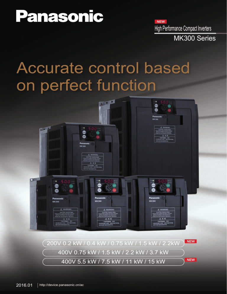
High Performance Compact Inverters MK300 Series Accurate control based on perfect function 200V 0.2 kW / 0.4 kW / 0.75 kW / 1.5 kW / 2.2kW 400V 0.75 kW / 1.5 kW / 2.2 kW / 3.7 kW 400V 5.5 kW / 7.5 kW / 11 kW / 15 kW 2016.01 2015.12 http://device.panasonic.cn/ac MK300 Compact inverters with industry-leading control performance • Top class overload and high-torque • Selected for dual-specification of standard load and light load performance among small models The product has clearly marked inverter power • Mode-selectable sensorless vector performance, which serves as a reference to the user in model selection. control function The effect of "small horse drawing a big car" can be realized for particular industries. Drive common motor without encoder to achieve high precision and high response speed. 200% torque output can be achieved at speed as low as 0.5Hz (in sensorless vector control mode). • Standard load specification Overload current rating: 150% of rated output current, 1 minute. It can address motor applications of standard load specification of the current inverter. • Light load specification Overload current rating: 120% of rated output current, 1 minute. It can address motor applications that are one grade higher than the current inverter specification. Note) 150% torque output at 0.5Hz for 5.5kW or more Speed - torque characteristics example AMK3001P54 (sensorless vector control) Motor: 1.5kW 4P Conveyor control application 250% 200% With torque control, superior driving power can be exerted in applications such as low speed starting. 150% Load Torque(%) 100% 3Hz 10Hz 25Hz 50Hz 50% 0% 0 200 400 600 800 1000 1200 1400 -50% 1600 Rotational speed (r/min) -100% -150% -200% -250% A rich variety of functions and applications • Provided with a high-speed current limiting function Even if excessive current flows momentarily due to load variation, MK300 will continue operation instead of tripping, thus improving productivity. It is effective for rapid acceleration of heavy-duty turntable and stirring of viscous substances like bread and flour, etc. Impact load 5A 1 0.2 sec Operation can continue due to the high-speed current limiting function 200V 0.2kW 200V 0.4kW 200V 0.75kW 200V 1.5kW 400V 0.75kW 400V 1.5kW 200V 2.2kW 400V 2.2kW 400V 3.7kW High Performance Compact Inverters • Corresponds to textile winder function Textile winding reciprocal operation function will operate at the triangular-wave-shaped frequency as shown in the following graph. Textile machinery application Applied in most textile equipment using inverters. Textile winding reciprocal operation function Winding mode control function will operate at the triangular-wave-shaped frequency as shown. Upper peak Set frequency Lower peak Time Start/stop Winding mode Pause switch Random mode Common mode Random oscillation within the set range More operation modes: • Random oscillation mode Effectively prevent the windings from Convenient operation • Quick selection operation with knob It includes a knob for confirming buttons, which enables quick selection and setting when selecting parameters. The operational speed and precision are improved. stacking on the same point • Winding length stop mode The function of auto stop when the winding accumulatively reaches a certain length • Pulse input length calculation mode It facilitates the display and statistics of winding length, and the calculation results can be communicated • Two-point mode The reference frequency is smoothed with the winding length, and finally changes to the second frequency Rotation selection parameter Button confirmation parameter Free maintenance • Simple exchange of cooling fan The exquisite design at the cooling fan makes it more convenient to replace the cooling fan. The product maintenance efficiency is greatly improved. 400V 5.5kW 400V 7.5kW 400V 11kW 400V 15kW 2 MK300 Accessories Product name Model Product image MK300 AMK300-REM1 operation panel Supply voltage Communication pattern MK300 inverter body power supply (+5V) RS485 Function Main features • Requires no other power supply (MK300 Remote operation body power supply) function Parameter • Requires no special connecting cable copy function (can be connected using commercially Inverter multi-unit available standard LAN cable) control function • Can be installed using two M3 screws The water tank pump pressure is controlled using our small PLC<FP-XH> and MK300 Flow meter ① Filter Flow meter ② Canteen discharged water 4mA to 20mA 4mA to 20mA Analog input Analog input Used in factory Water usage Control cabinet Decomposing tank Settling tank Water storage tank MK300 0V to 10V FP-XH Analog output Application description • The water discharged from the factory canteen is bacterially decomposed, and the fresh water accumulated in the settling tank is drawn using a pump, and after filtration using a filter, the water is sent to the storage tank as industrial water. • MK300 is used to control the motor speed so as to regulate the pump pressure. • PLC[FP-XH] is used to output speed instructions to MK300, and (0V-10V) is used to analog signal. • The speed instruction output from FP-XH (0V-10V analog output) is based on the value of flow meter ②. After the value of flow meter becomes small, the analog output value is increased in order to boost the pump pressure. • After the value difference between flow meter ① and flow meter ② exceeds a certain value, it is judged that the filter is clogged, and a replacement signal is output from FP-XH. • After installing the analog I/O plug-in (AFPX-A21) onto FP-XH, the analog input of two flow meters and analog output of MK300 can be realized,and by utilizing the expanded plug-in of small installation area in combination with inverter MK300, great contribution can be made to the miniaturization of control cabinets. Small programmable controllers FP-XH series product introduction • High speed, high performance Basic instructions: 0.04ms within 5k steps; Large capacity of 32k by default (16k for 14-point model), programs/registers 3-phase capacity changeover. • Position control All channels, maximum speed up to 100kHz, maximum 6-channel high-speed pulse output, versatile motion control including linear interpolation, home return, repetitive motion, etc. • Scalability and compatibility A full lineup of expansion cards and expansion units, up to 452 points; simultaneous extended 4ch communication; used in common with the existing FP-X program. • Communication Terminal block type RS232C communication port, cardless PC-Link; expanded RS485 communication card, enabling data share among up to 16 control units. 3 High Performance Compact Inverters RATINGS Item Applicable motor output (kW) *1 Rated output current (A) *2 Standard load Rated output capacity (kVA) *3 specification Rated input current (A) *4 Power supply capacity (kVA) *4 Applicable motor output (kW) *1 Rated output current (A) *2 Light load Rated output capacity (kVA) *3 specification Rated input current (A) *4 Power supply capacity (kVA) *4 Weight (kg) 1-phase 200 V Input Type 3-phase 400 V Input Type (Model AMK300□□□2) (Model AMK300□□□4) 0P2 0P4 0P7 1P5 2P2 0P7 1P5 2P2 3P7 5P5 7P5 011 015 0.2 0.4 0.75 1.5 2.2 0.75 1.5 2.2 3.7 5.5 7.5 11.0 15.0 1.5 3.0 5.0 8.0 11.0 2.6 4.0 6.0 9.5 12.0 17.0 23.0 31.0 0.6 1.2 2.0 3.2 4.4 2.1 3.2 4.8 7.6 9.6 13.5 18.3 24.7 3.9 8.0 12.6 18.5 23.8 3.9 6.0 9.0 14.3 15.6 22.1 29.9 40.3 0.9 1.8 2.9 4.3 5.5 3.1 4.8 7.2 11.4 12.4 17.6 23.8 32.1 0.4 0.75 1.5 2.2 3.0 1.5 2.2 3.7 5.5 7.5 11.0 15.0 18.5 1.9 3.5 6.0 9.6 12.0 3.6 5.4 6.9 11.1 17.0 17.0 31.0 38.0 0.8 1.4 2.4 3.8 4.8 2.9 4.3 5.5 8.8 13.5 13.5 24.7 30.3 5.1 9.1 15.2 22.3 25.8 5.4 8.1 10.4 16.7 22.1 22.1 40.3 49.4 1.2 2.1 3.5 5.1 5.9 4.3 6.5 8.2 13.3 17.6 17.6 32.1 39.4 Approx. 1.0 Approx. 1.0 Approx. 1.4 Approx. 1.6 Approx. 2.0 Approx. 1.5 Approx. 1.6 Approx. 1.9 Approx. 2.0 Approx. 3.6 Approx. 3.6 Approx. 8.2 Approx. 8.3 *1 "Applicable motor output" refers to the maximum applicable capacity of standard 4-pole motor.Make sure that the rated output current of inverter is higher than the rated current of motor during inverter selection. *2 The rated output current of inverter varies with the set carrier frequency. Derate the output current for use. *3 Rated output capacity refers to the value at output voltage of 230 VAC for 1-phase 200V input type and the value at output voltage of 460 VAC for 3-phase 400V input type. *4 The power supply capacity varies with the impedance at its side. Prepare the power supply with capacity larger than values shown in the above table. Terminals for main circuit ■ 1-phase 200V / 0.2kW, 0.4kW Terminals for control circuit • Control circuit terminal arrangement Power supply Braking resistor Circuit breaker for wiring Motor Ground terminal Symbol for grounding ■ 1-phase 200V / 0.75kW-2.2kW Power supply Terminals for braking unit only (COM) 11 12 13 14 15 16 17 18 Motor Power supply Circuit breaker for wiring Motor Ground terminal Braking resistor Symbol for grounding ■ 3-phase 400V / 0.75kW-15kW Power supply Terminals for braking unit only 0V to 5V 0V to 10V 4mA to 20mA 0mA to 20mA } +- + } 2 1 3 4 5 6 7 8 Circuit breaker for wiring Symbol for grounding Braking resistor ×2 Terminal name Power supply for main circuit Inverter output Braking resistor connection Internal DC voltage (negative) Grounding Descriptions of terminal function Power supply for main circuit For 1-phase 200 V type, connect to terminal L1 and L2 Connects to 3-phase motor Connects to braking resistor Negative terminal of internal DC voltage Ground terminal 1-phase 200V: ground resistance 100 Ω or less 3-phase 400V: ground resistance 10 Ω or less Ground the neutral of power supply 9 10 C1 C2 Motor • Functions of terminals for main circuit Terminal No. R/L1,S/L2,T/L3 L1,L2 U, V, W P/DB+, DBN- 0V to 5V 0V to 10V 4mA to 20mA 0mA to 20mA (COM) Power supply Ground terminal E RS485 communication port Analog output (0V to 10V) Motor D- D+ - + VR SW1 SW2 SW3 SW4 Relay output A B C NO SW5 SW6 E Open-collector output (TR1, TR2) Open-collector specification: 50 VDC, 50 mA NC COM VR specification: 10 kW,1/4 W or higher potentiometer Relay specification: 1c non-voltage contact 230 VAC 0.25 A (resistive load) 30VDC 1 A (resistive load) 4 MK300 Specification Item Standard output of applicable motor (kW) Rated voltage Rated output Overload current rating Input power supply Output frequency Standard load specification: 150% of rated output current, 1 minute Light load specification: 120% of rated output current, 1 minute 3-phase 380V-460VAC 50Hz/60Hz Instantaneous voltage drop • Operation continues when voltage is above 165 VAC. ride-through capability • Operation continues for 15 ms when voltage drops below 165 VAC. • Operation continues when voltage is above 323 VAC. • Operation continues for 15 ms when voltage drops below 323 VAC. Frequency range V/F control: 0.2 Hz to 400 Hz Sensorless vector control: 0.5 Hz to 120 Hz Frequency display Digital display Frequency precision Analog setting: within ±0.5% of maximum set frequency (25°C±10°C) Digital setting: within ±0.01% of maximum set frequency (-10°C to +50°C) Frequency resolution Analog setting: 0.1 Hz (in 50/60 Hz mode) Digital setting: 0.1 Hz Carrier frequency(Note 3) Control 0.75 kW to 15 kW 3-phase 380V-460VAC (proportional to power supply voltage) Phase number/Voltage/Frequency 1-phase 200V-230VAC 50Hz/60Hz Allowable voltage fluctuation +10% and -15% of rated input AC voltage Allowable frequency fluctuation ±5% of rated input frequency Inverter control mode Run Specification 0.2 kW to 2.2 kW 1-phase 200V-230VAC (proportional to power supply voltage) High carrier frequency sinusoidal PWM control (V/F control or sensorless vector control is available.) • V/F control setting: 9 options (adjustable from 0.8 to 15 kHz) can be selected. • Sensorless vector control setting: 6 options (adjustable from 2.5 to 15 kHz) can be selected. (0.8kHz, 1.1kHz,1.6kHz, 2.5kHz, 5.0kHz, 7.5kHz, 10.0kHz, 12.5kHz, 15.0kHz) Start/Stop • Operation panel switches • 1a contact signal and 3-wire input (1a and 1b contact signals) can be selected. • RS485 communication • Wait time (0.1 to 100 s) can be set. Forward/Reverse run • Operation panel switches • 1a contact signal (reverse run can be disabled.) • RS485 communication Jogging operation Operating frequency: adjustable from 0.2 to 400 Hz Acceleration / deceleration time: adjustable from 0.04 to 3600 s Stop Mode Reset function Starting Frequency Stop Frequency Ride-through restart selection Speed search Deceleration stop / coast-to-stop (switchable) Reset by stop signal/reset by external device/reset by operation panel(optional) / reset by power supply Adjustable from 0.2 to 60 Hz Adjustable from 0.2 to 60 Hz 0 Hz restart/operation frequency restart/speed search restart (switchable) Speed search during startup (optional) Retry function Retry selection: validity of function, selection of details of retry faults Retry operations: adjustable from 1 to 10 operations Frequency setting signal Panel setting (operation panel): digital setting Analog setting signal input from external control: • Potentiometer (10 kΩ, 1/4 W or higher) • 0V to 5V DC, 0V to 10V DC • 4 mA to 20 mA, 0 mA to 20 mA Digital setting signal input from external control: • PWM signal (signal cycle: 1 to 2000 ms), pulse input signal • Frequency rise SW/reduction SW/storage SW signal Communication setting: RS485 Frequency/Voltage characteristics Base frequency: fixed at 50/60 Hz, adjustable from 45 to 400 Hz 3-point V/F mode: adjustable voltage and frequency V/F curve: constant/reduced torque mode (switchable) Torque boost Adjustable from 0 to 40%/auto torque boost (switchable) Acceleration/deceleration time 0.04 to 3600 s (independent acceleration/ deceleration setting) Acceleration/deceleration characteristics Linear and S-shaped acceleration/deceleration (switchable) 2nd function selection 2nd function selection (acceleration/deceleration time, torque boost, V/F characteristics (base frequency/3-point V/F mode), electronic thermal and analog frequency setting) Multi-step speed frequency setting • Multi-step speed operation: up to 16-step speed setting (No limitation to frequency setting) • Timer operation: up to 8-step speed settings (No limitation to frequency setting) It can be linked with acceleration/ deceleration time. Skip frequency setting Up to 3 settings (skip frequency band adjustable from 1 to 10 Hz) Upper frequency limit setting Adjustable from 0.2 to 400 Hz 5 High Performance Compact Inverters Item Control Specification Lower frequency limit setting Bias/gain frequency setting External stop function PID function Offline automatic tuning function Cooling fan ON/OFF control Communication Function Regenerative braking torque Braking DC injection braking Analog output Output signal Open-collector output Relay output Display Protection Environment Adjustable from 0.2 to 400 Hz Bias frequency: adjustable from -99 to 250% Gain frequency: adjustable from 0 to 500% External fault stop/coast-to-stop (switchable) PID control mode (optional) Automatic tuning of motor constant Optional • Port: RS485 serial communication • Communication speed: 4800bps/9600bps/19200bps/38400bps/57600bps/115200bps (switchable) • Protocols: MEWTOCOL-COM/Modbus-RTU/Modbus-ASCII (switchable) • Communication method: half-duplex • Maximum number of connected units: 31 • Maximum transmission distance: 500 m (in total) • 200V 0.2 kW: 100% or higher 0.4 kW: 80% or higher 0.75 kW to 2.2 kW: 20% or higher • 400V 0.75 kW to 15 kW: 20% or higher Operate at the frequency below stop frequency • Braking torque level: 0 to 100% • Braking time: adjustable from 0.1 to 120 s Output specification: 0 to 10 VDC (max. 1 mA) Output function: output frequency and output current proportion (switchable) Output specification: max. rating 50 VDC/50 mA Output functions: operation signal, arrival signal, overload alarm, frequency detection, reverse run signal, abnormal alarm, current detection, timer OFF signal and output frequency/current proportion PWM signal (cycle: 1ms) (switchable) Output specification: 1c contact (contact capacity 230 VAC, 0.25 A resistive load, 30 VDC, 1 A resistive load) Output functions: operation signal, arrival signal, overload alarm, frequency detection, reverse run signal, abnormal alarm, current detection and timer OFF signal (switchable) Output frequency, linear speed display (switchable), rotation direction Output voltage, internal DC voltage, setting frequency, communication station No., operation times of timer, Operation/Control status alarm type, control circuit terminal status (I/O signal), operation status, PID (setting value, measured value and output value), progress of automatic tuning, accumulative operation time and accumulative operation time of fan Details of abnormality Specific symbol is indicated when the protection function is activated (the latest four abnormalities are stored.) Current limit Current limit can be set within 1 to 200% of rated output current. Instantaneous overcurrent (SC1-6), abnormal temperature (OH) (Note 2) Trip (stop) Overcurrent (OC1-3), overload and electronic thermal relay (OL), undervoltage (LU), overvoltage (OU1-3), cooling fan fault (FAn, FAn2), external fault (AU), operation fault (OP) and CPU fault (CPU) Stall prevention function Overcurrent and overvoltage stall prevention Ambient temperature and humidity -10 to +50°C (Note 1) (without freezing) and below 90%RH (without condensation) Storage temperature and humidity -25 to +65°C and below 95%RH Vibration 5.9 m/s2 (0.6G) or lower Altitude 1000 m max. Location Indoor areas free of corrosive gases, flammable gases, oil mist or dust IP protection IP20 cabinet-mounted Cooling method 0.75 kW or lower: natural cooling, 1.5 to 15 kW: air cooling Note 1) It is -10 to +40°C when multiple inverters are installed side-by-side. Temperature for 5.5 to 15 kW light load specification: -10 to +40°C. Note 2) The temperature protection level will be automatically changed when the output frequency is low. Note 3) The carrier frequency will be automatically changed inside the inverter when the output frequency is low. Product purchase numbering system 1 Series name MK300 2 Applicable motor capacity 1-phase 200V 0.2kW-2.2kW 3-phase 400V 0.75kW-15kW A MK300 0P7 4 1 2 3 (Standard load specification) 0P2: 0.2kW 3P7: 3.7kW 0P4: 0.4kW 5P5: 5.5kW 0P7: 0.75kW 7P5: 7.5kW 1P5: 1.5kW 011: 11.0kW 2P2: 2.2kW 015: 15.0kW 3 Voltage class 2: 1-phase 200V Voltage class 4: 3-phase 400V 6 DIMENSIONS (Unit: mm) • MK300 Inverter 〈For 0.75kW or more〉 〈For 200V/0.2kW, 0.4kW〉 2-fd (Mounting hole) (Note 1) 4-fd (Mounting hole) (Note 1) ALM FWD H STOP H1 ESC H1 RUN H PROG REV MODE 10 W1 W D D 24 5 5 W1 W • AMK300-REM1 Operation Panel ■ 1-phase 200 V Input Type (Accessories sold separately) 2-f3.5 (Mounting hole) AMK300-REM1 FWD 64 ALM Panel cut-out PROG. ESC STOP 10.3 17.4 72 9.4 Inverter capacity AMK3000P74 AMK3001P54 AMK3002P24 AMK3003P74 AMK3005P54 AMK3007P54 AMK3000114 AMK3000154 4 2.5 2-M3 (Mounting hole) (Note 2) 56 Unit: mm W1 W H1 H D Φd 63 72 131 140 146 5 100 110 130 140 156 5 130 140 130 140 156 5 ■ 3-phase 400 V Input Type 64 RUN 69 MODE 72 REV. Inverter capacity AMK3000P22 AMK3000P42 AMK3000P72 AMK3001P52 AMK3002P22 64 Dimensions of panel cut-out (A view) 64 【Manufacturer】 Panasonic Industrial Devices SUNX Suzhou Co., Ltd. No.97 Huoju Road, New District Suzhou, Jiangsu Province, China Unit: mm W1 W H1 H D Φd 100 110 130 140 156 5 130 140 130 140 156 5 150 160 190 200 185 5 204 220 265 280 185 7 Note 1) M6 screw is used in mounting holes for AMK300114 and AMK300154, while M4 screw is used in other mounting holes. Note 2) M3 screw is used in mounting holes. Please contact Panasonic Industrial Devices Sales (China) Co., Ltd. Automation Business Office Panasonic Industrial Devices Sales (China) Co., Ltd. Business consultation: Registered Address: 2F, Buildings 7 & 8, No. 88, Maji Road, Beijing: 3F, Block C, Yuanyang Guanghua International Center, No.5 Jinghua South Street, Chaoyang District, Beijing Tel: 010-59255988 Shanghai: Floor 6, China Insurance Building, NO.166 East LuJiaZui Road, Pudong New District, Shanghai Tel: 021-38552000 Contact Address: Floor 6, China Insurance Building, NO.166 East LuJiaZui Road, Pudong New District, Shanghai Guangzhou: Floor 9, China Hotel Commercial Mansion, Liuhua Road, Yuexiu District, Guangzhou Tel: 020-87130888 Dalian: 6F, Modern Service Headquarters Building, No.620 Huanghe Road, Shahekou District, Dalian Tel: 0411-88008679 Shenyang: Floor 18, Fulihua International Business Center, Block B, No.69-1 Zhonghua Road, Heping District, Shenyang Tel: 024-31884848 Chengdu: Room 01-03, Floor 23, Block 2, Zhonghuan Plaza, No.8 Shuncheng Avenue, Chengdu Tel: 028-62828333 Chongqing: Room 1701-12A, Metropolitan Plaza, No.68 Zourong Road, Yuzhong District, Chongqing Tel: 023-63803502 Shenzhen: Floor 8, Block 3, Jiali Construction Plaza, No.1-1 Central Fourth Road, Futian District, Shenzhen Tel: 0755-82558888 Tianjin: Room 1001, Tianjin International Building, No.75 Nanjing Road, Heping District, Tianjin Tel: 022-58969100 Jiangsu: 13F, Jiangsu Yihua Hotel Office Building, No.45 North Zhongshan Road, Gulou District, Nanjing Tel: 025-85288072 Hangzhou: Block C, Floor 4, Zhejiang Materials & Products International Plaza, No.445, Kaixuan Road, Hangzhou Tel: 0571-85171900 Wuhan: Room 1706-07, World Trade Building, No.686 Jiefang Avenue, Wuhan Tel: 027-85711665 Zhengzhou: Room 1512, Future Building, No.69 Weilai Road, Jinshui District, Zhengzhou Tel: 0371-65615120 Xi'an: Unit 04-05, Floor 7, Zhonghai Building, No.3 South Furong Road, Qujiang New Area, Xi'an Tel: 029-87607970 Qingdao: Room 90A, Zhongtianheng Building, No.8 South Fuzhou Road, Shinan District, Qingdao Tel: 0532-80900626 Xiamen: Room 2311, Bank Center, No.189 Xiahe Road, Xiamen Tel: 0592-2117208 China (Shanghai) Pilot Free Trade Zone Customer Service Hotline: 400-920-9200 Fax: 400-820-7185 URL: device.panasonic.cn/ac All Rights Reserved © 2015 COPYRIGHT Panasonic Industrial Device SUNX Suzhou Co., Ltd. CC-MK300-1-10 201506-10YCI Printed by: Akagane Computer Data Processing (Shanghai) Co., Ltd Address: 12F, Yingshi Building, NO.180 Tianjin Road, Shanghai Advertising


