Thermopile Time Constant Determination - Application Brief
Anuncio
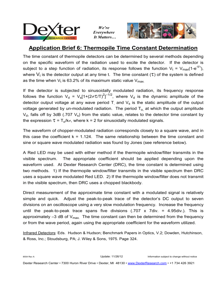
We’re Everywhere It Matters… Application Brief 6: Thermopile Time Constant Determination The time constant of thermopile detectors can be determined by several methods depending on the specific waveform of the radiation used to excite the detector. If the detector is -t/τ subject to a step function of radiation, its response follows the function Vt = Vmax(1-e ), where Vt is the detector output at any time t. The time constant (τ) of the system is defined as the time when Vt is 63.2% of its maximum static value Vmax. If the detector is subjected to sinusoidally modulated radiation, its frequency response follows the function Vd = Vs[1+(2πτ /T) ] 2 –1/2 , where Vd is the dynamic amplitude of the detector output voltage at any wave period T, and Vs is the static amplitude of the output voltage generated by un-modulated radiation. The period To, at which the output amplitude Vd, falls off by 3dB (.707 Vs) from the static value, relates to the detector time constant by the expression τ = To/kπ, where k = 2 for sinusoidally modulated signals. The waveform of chopper-modulated radiation corresponds closely to a square wave, and in this case the coefficient k = 1.124. The same relationship between the time constant and sine or square wave modulated radiation was found by Jones (see reference below). A Red LED may be used with either method if the thermopile window/filter transmits in the visible spectrum. The appropriate coefficient should be applied depending upon the waveform used. At Dexter Research Center (DRC), the time constant is determined using two methods. 1) If the thermopile window/filter transmits in the visible spectrum then DRC uses a square wave modulated Red LED. 2) If the thermopile window/filter does not transmit in the visible spectrum, then DRC uses a chopped blackbody. Direct measurement of the approximate time constant with a modulated signal is relatively simple and quick. Adjust the peak-to-peak trace of the detector’s DC output to seven divisions on an oscilloscope using a very slow modulation frequency. Increase the frequency until the peak-to-peak trace spans five divisions (.707 x 7div. = 4.95div.). This is approximately –3 dB of Vmax. The time constant can then be determined from the frequency or from the wave period, again using the appropriate coefficient for the waveform utilized. Infrared Detectors: Eds. Hudson & Hudson; Benchmark Papers in Optics, V.2; Dowden, Hutchinson, & Ross, Inc.; Stoudsburg, PA; J. Wiley & Sons, 1975. Page 324. 8554 Rev A Update: 11/26/12 Information subject to change without notice Dexter Research Center • 7300 Huron River Drive • Dexter, MI 48130 • www.DexterResearch.com • +1 734 426 3921
