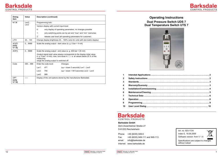
Dialog item Value Description (continued) V 7.X Lev0... Lev2 Programming lock: Operating Instructions Dual Pressure Switch UDS 7 Dual Temperature Switch UTS 7 Version display with current input level: 0: only display of operating parameters, no changes possible 1: only switching points can be set and “max” and “min” memories 2: release user level (all operating parameters for customer) LITH 20... 100 Change display brightness 20... 100% (only for units with dot-matrix display) AOZS (only V 7.X) 0... 9999 Scale the analog output - start value (e. g. 0 bar = 4 mA) AOFS 0... 9999 Scale the analog output - end value (e. g. 400 bar = 20 mA) ((output signal start value always corresponds to the display initial value, e. g. 0 bar = 4 mA), max. turn-down 4: 1, i. e. at values below 25 % of the measuring range the analog output is switched off Code OPT (only V 7.X) 000... 999 ----- Enter the code level: Changes: Lev1: 471 (up + down 5 seconds) Lev1 - Lev0 Lev2: 740 (up + down + M 5 seconds) Lev2 - Lev0 Lev0: 999 Display of the unit options stored by the manufacturer Barksdale. 1 Intended Applications ................................................................................................. 2 2 Safety Instructions ...................................................................................................... 2 3 Standards..................................................................................................................... 3 4 Warranty/Guaranty ...................................................................................................... 3 5 Installation/Commissioning ........................................................................................ 4 6 Maintenance/Cleaning ................................................................................................. 5 7 Technical Data ............................................................................................................. 6 8 Operation ..................................................................................................................... 8 9 Programming ............................................................................................................... 9 10 User Level Dialog ...................................................................................................... 10 Barksdale GmbH Dorn-Assenheimer Straße 27 D-61203 Reichelsheim +49 (6035) 949-0 Index E, 19.08.2009 Fax: +49 (6035) 949-111 and 949-113 Software version: from V 1.X email: info@barksdale.de Specifications are subject to changes without notice! Internet: www.barksdale.de 12 Art. no. 923-1724 Phone: 1 1 Intended Applications Disposal The dual pressure switch monitors system pressures and has up to two switching outputs and one analog output. The sensor must be disposed of correctly in accordance with the local regulations for electric/electronic equipment. The dual temperature switch monitors the temperature of the medium into which the probe is immersed and has up to two switching outputs and one analog output. DANGER The switch must not be disposed of with the household garbage! 3 The standards applied during development, manufacture and configuration are listed in the CE conformity and manufacturer's declaration. The switch may only be used in the specified fields of application. The temperature must be within the specified ranges, the pressure values and the electrical rating must not exceed the values specified. Observe also the applicable national safety instructions for assembly, commissioning and operation of the switch. The switch is not designed to be used as the only safety relevant element in pressurized systems according to DGR 97/23/EC. 2 Safety Instructions The safety instructions are intended to protect the user from dangerous situations and/or material damage. In the operating instructions the seriousness of the potential risk is designated by the following signal words: Standards 4 Warranty/Guaranty Warranty Our scope of delivery and services is governed by the legal warranties and warranty periods. Terms of guaranty We guaranty for function and material of the dual pressure and temperature switch under normal operating and maintenance conditions in accordance with the statutory provisions. Loss of guaranty The agreed guaranty period will expire in case of: • • • incorrect use, incorrect installation or incorrect handling or operation contrary to the provisions of these operating instructions. No liability is assumed for any damage resulting therefrom, or any consequential damage. DANGER Refers to imminent danger to men. Nonobservance may result in fatal injuries. WARNING Refers to a recognizable danger. Nonobservance may result in fatal injuries, and destroy the equipment or plant parts. CAUTION Refers to a danger. Nonobservance may result in light injuries and material damage to the sensor and/or to the plant. IMPORTANT Refers to important information essential to the user. 2 3 5 Installation/Commissioning 6 Maintenance/Cleaning Maintenance DANGER Only install or uninstall the switch when deenergized (electrically and hydraulically/pneumatically). Pressure connection and electrical connection must be carried out by trained or instructed personnel according to state-of-the-art standards. The switch must only be installed in systems where the maximum pressure Pmax or the maximum temperature Tmax is not exceeded (see type label). The pressure/temperature switch requires no maintenance. Cleaning CAUTION The membrane keys may be damaged by the use of unsuitable cleaning agents. Do not use any cleaning agents containing solvents or abrasive additives. WARNING Be aware of the fact that in case of operation with higher temperatures the casing surface may become very hot! CAUTION Mount the pressure switch from bottom to the fitting with a wrench SW 36 (1/4“) resp. 19 with 45 Nm torque. Do not operate the switch if the switch itself or the connection cable is damaged. Impact and heavy vibrations during transportation should be avoided. Even if the switch casing remains undamaged, inside parts may be damaged and cause malfunctions. Electrical connection depends on the type of pressure switch (see type label) according to the chart below. Wrong assignment of the connections may cause malfunctions or incorrect switch outputs. Connection Chart Plug M 12x1 4-pin / 5-pin Model with 2 switching outputs Model with 2 switching outputs and 1 analog output Pin 1 +Ub: 18... 32 V DC +Ub: 18... 32 V DC Pin 2 SP2 0.5 A max. analog: 4… 20 mA / 0... 10 V DC Pin 3 0V 0V Pin 4 SP1 0.5 A max. SP1 0.5 A max. Pin 5 4 SP2 0.5 A max. 5 Operating and display elements/Dimensions Measuring element Piezoresistive pressure sensor with internal stainless steel diaphragm Pt100 (class B) according to DIN IEC 751 Measuring ranges 0… 1 bar to 0… 10 bar 0… 15 psi to 0… 150 psi absolute pressure 0 ... +100 °C to -30 ... +150 °C +32 ... +212 °F to -22 ... +302 °F Dual pressure switch UDS7 approx 35 120 LEDs (1) 0 ... 10 bar to 0 ... 600 bar 0 ... 150 psi to 0 ... 9000 psi relative pressure 4-digit dot-matrix display, green, digit height 5 mm 2 x transistor switching output, pnp NO/NC function (programmable), adjustable switching time delay 0... 9.9 s G ¼, G ½ front flush 1/4" – 18 NPT 7/16 – 20 SAE G ¼, 1/4" – 18 NPT 120 Change dialog items/functions, change numerical values Dual temperature switch UTS7 approx 35 131 17 12 Protection system/class Nema 4X, IP65/III Electrical connection Plug 5-pin, M 12x1 Auxiliary power (green) – switching point 2 Dialog item "change to value/to function", acknowledge inputs G1/4 Process connection (fitting "A" without adapter) -30 ... +150°C / -22 ... +302 °F (green) – switching point 1 S2 12 -10 ... +70°C / +14 ... +158 °F -25 ... +100°C / -13 ... +212 °F (yellow) – alarm S1 18... 32 V DC 2 approx 48 *L0 6 For further technical data and options please refer to the data sheets 32 Operating temperature range approx 48 2 AL Membrane keys (2) HXN27 Switching outputs Media temperature range 1 G1/4 Display 14 32 UTS 7 G1/2 UDS 7 Dimensions in mm HXN19 Technical Data HXN27 32 7 6 7 8 Operation 9 Programming The switch may be installed and operated only by authorized persons. Do not use any hard objects for 1 In case of first commissioning a self-test is performed. The device is menu-operated via three membrane keys, which must not be touched with any hard objects. 2 If an error is detected during the self-test or normal operation, this error is signaled by a (yellow) flashing alarm LED (AL). The error can be read out in the menu ERRC . 3 Activate dialog item Value input/function selection 4 Change value making entries. change to the first dialog item. After switching on with Change dialog item Select the desired dialog item with (see chapter 10 „User Level Dialog) The green LEDs S1 and S2 signal the activity of the two switching points. or . to change the corresponding value or Activate the desired dialog item with the desired function. . Select the individual digits with Change the numerical value with or and acknowledge with . If the entered value is within the permissible range, the system changes to the dialog item after input of the last digit, otherwise the 1st digit will flash again. 5 Change function Change the function with Activate key lock Simultaneously press or + during this time. On activation, and acknowledge with . for at least 5 s. The display must not change * appear in succession. and e. g. Key lock active Values or functions will be displayed but cannot be changed. LOCK will be displayed when attempting a change. Deactivate key lock + for at least 5 s. Simultaneously press (siehe Kapitel 10 „User Level Dialog, dialog item: CODE) Return to measuring mode If no entry is made for 2 minutes, the switch automatically returns to the measuring mode without accepting the entries. Terminate programming Press for at least 5 s to change to the measuring mode. * Software version no. 8 9 10 User Level Dialog (xxxx = 125% v. f. s.) Dialog item Value Value ON-2 -1... xxxx Description Description (continued) Switch-on point for SP2 NOTE: if the ON-value is set smaller than the OFF-value you receive a decreasing switch point evaluation. MENU -1... 9999 Primary display, e.g. the value selected in the DISP menu OFF-2 -1... xxxx Switch-off point for SP2 DISP ----- Display value which should be permanently in the display: DLY2 0.0... 9.9 s Switch-on / switch-off delay for SP2 in seconds act actually measured value INV-2 ----- Inversion of switching output SP2 sp1 switching point SP1 hlfs high-level-fail-save (normally open function) SP2 switching point SP2 llfs low-level-fail-save (normally closed function) ACT. -1... 9999 UNIT (only V 7.X) SP.1 ON-1 ----- -1... xxxx max maximum peak value MAX -1 min minimum peak value CLRH Display of the peak value "max“ ----- Delete the maximum value memory ----- no deletion Fixing the unit (The unit is shown in the display appr. every 30 sec for appr. 5 sec) clr delete value CDLY 0.0... 9.9 s Time setting to delete the maximum value memory after switching point SP1 is reached (manual deletion is still possible) = psi x 10 MIN -1... xxxx Display of the peak value "min“ = psi CLRL ----- bar bar = bar psi psi x psi psi hPa hPa = Hekto-Pascal mbar mbar = millibar Delete the minimum value memory ----- no deletion clr delete value NOTE: no choice of the unit possible at UTS 7. Only °C possible! OFFS -9.9... +xx Measured value offset in bar none switching output SP1 deactivated CUT 0.0... +xx Cut-off i.e. signal suppression at measuring range start in bar wind window technology DLDS 0.0... 9.9 s Time delay for currently displayed value in seconds stnd standard evaluation SP1 ERRC ----- Error display: erro error output 0: -ok- no error Switch-on point for SP1; 1: max exceeding pos. meas. range NOTE: if the ON-value is set smaller than the OFF-value you receive a decreasing switch point evaluation. 2: min exceeding neg. meas. range 3: dig1 switching output 1 error 4: dig2 switching output 2 error 5: anao analog output error 6: sens sensor error 7: data data error (EEProm) 8: prog program error 9: cal calibration error -1... xxxx Switch-off point for SP1 DLY1 0.0... 9.9 s Switch-on / switch-off delay for SP2 in seconds INV-1 ----- Inversion of switching output SP1 ----- ... xxxx Display of actually measured value in bar OFF-1 SP.2 10 Dialog item hlfs high-level-fail-save (normally open function) Ilfs low-level-fail-save (normally closed function) none Switching output deactivated wind window technology stnd standard evaluation SP2 erro error output 11
