Rehabilitation of Historic Masonry Bridges: Lessons
Anuncio
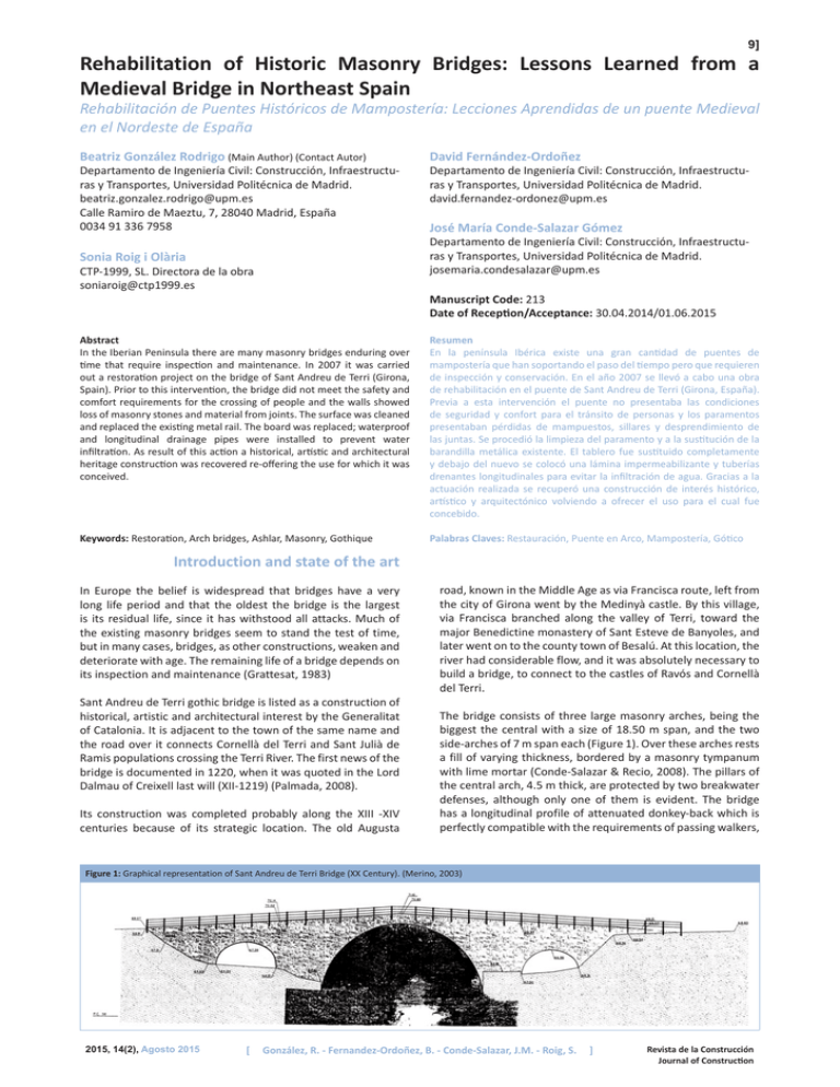
9] Rehabilitation of Historic Masonry Bridges: Lessons Learned from a Medieval Bridge in Northeast Spain Rehabilitación de Puentes Históricos de Mampostería: Lecciones Aprendidas de un puente Medieval en el Nordeste de España Beatriz González Rodrigo (Main Author) (Contact Autor) Departamento de Ingeniería Civil: Construcción, Infraestructuras y Transportes, Universidad Politécnica de Madrid. beatriz.gonzalez.rodrigo@upm.es Calle Ramiro de Maeztu, 7, 28040 Madrid, España 0034 91 336 7958 David Fernández-Ordoñez Departamento de Ingeniería Civil: Construcción, Infraestructuras y Transportes, Universidad Politécnica de Madrid. david.fernandez-ordonez@upm.es José María Conde-Salazar Gómez Departamento de Ingeniería Civil: Construcción, Infraestructuras y Transportes, Universidad Politécnica de Madrid. josemaria.condesalazar@upm.es Sonia Roig i Olària CTP-1999, SL. Directora de la obra soniaroig@ctp1999.es Manuscript Code: 213 Date of Reception/Acceptance: 30.04.2014/01.06.2015 Abstract In the Iberian Peninsula there are many masonry bridges enduring over time that require inspection and maintenance. In 2007 it was carried out a restoration project on the bridge of Sant Andreu de Terri (Girona, Spain). Prior to this intervention, the bridge did not meet the safety and comfort requirements for the crossing of people and the walls showed loss of masonry stones and material from joints. The surface was cleaned and replaced the existing metal rail. The board was replaced; waterproof and longitudinal drainage pipes were installed to prevent water infiltration. As result of this action a historical, artistic and architectural heritage construction was recovered re-offering the use for which it was conceived. Resumen En la península Ibérica existe una gran cantidad de puentes de mampostería que han soportando el paso del tiempo pero que requieren de inspección y conservación. En el año 2007 se llevó a cabo una obra de rehabilitación en el puente de Sant Andreu de Terri (Girona, España). Previa a esta intervención el puente no presentaba las condiciones de seguridad y confort para el tránsito de personas y los paramentos presentaban pérdidas de mampuestos, sillares y desprendimiento de las juntas. Se procedió la limpieza del paramento y a la sustitución de la barandilla metálica existente. El tablero fue sustituido completamente y debajo del nuevo se colocó una lámina impermeabilizante y tuberías drenantes longitudinales para evitar la infiltración de agua. Gracias a la actuación realizada se recuperó una construcción de interés histórico, artístico y arquitectónico volviendo a ofrecer el uso para el cual fue concebido. Keywords: Restoration, Arch bridges, Ashlar, Masonry, Gothique Palabras Claves: Restauración, Puente en Arco, Mampostería, Gótico Introduction and state of the art In Europe the belief is widespread that bridges have a very long life period and that the oldest the bridge is the largest is its residual life, since it has withstood all attacks. Much of the existing masonry bridges seem to stand the test of time, but in many cases, bridges, as other constructions, weaken and deteriorate with age. The remaining life of a bridge depends on its inspection and maintenance (Grattesat, 1983) Sant Andreu de Terri gothic bridge is listed as a construction of historical, artistic and architectural interest by the Generalitat of Catalonia. It is adjacent to the town of the same name and the road over it connects Cornellà del Terri and Sant Julià de Ramis populations crossing the Terri River. The first news of the bridge is documented in 1220, when it was quoted in the Lord Dalmau of Creixell last will (XII-1219) (Palmada, 2008). Its construction was completed probably along the XIII -XIV centuries because of its strategic location. The old Augusta road, known in the Middle Age as via Francisca route, left from the city of Girona went by the Medinyà castle. By this village, via Francisca branched along the valley of Terri, toward the major Benedictine monastery of Sant Esteve de Banyoles, and later went on to the county town of Besalú. At this location, the river had considerable flow, and it was absolutely necessary to build a bridge, to connect to the castles of Ravós and Cornellà del Terri. The bridge consists of three large masonry arches, being the biggest the central with a size of 18.50 m span, and the two side-arches of 7 m span each (Figure 1). Over these arches rests a fill of varying thickness, bordered by a masonry tympanum with lime mortar (Conde-Salazar & Recio, 2008). The pillars of the central arch, 4.5 m thick, are protected by two breakwater defenses, although only one of them is evident. The bridge has a longitudinal profile of attenuated donkey-back which is perfectly compatible with the requirements of passing walkers, Figure 1: Graphical representation of Sant Andreu de Terri Bridge (XX Century). (Merino, 2003) 2015, 14(2), Agosto 2015 [ González, R. - Fernandez-Ordoñez, B. - Conde-Salazar, J.M. - Roig, S. ] Revista de la Construcción Journal of Construction chariots and horsemen. This profile is very adequate as banks are set low over the water and facilitates the provision of certain light arches, allowing a proper conformation and the passage of water. (Manterola, 2006) (Figure 1). The bridge has undergone several renovations throughout its history, visible in the different types of stone used, possibly due to damaging caused by River Terri floods. However, it has retained to the present its basic structure (Merino, 2003). Despite the archaeological work done a few years ago, we could not clarify the date of construction, nor find documents about reforms earlier than the late nineteenth century (Palmada, 2008). The bridge suffered in the late nineteenth and early twentieth century an expansion project consisting of iron railings, as referred in the files of the Architectural Heritage Service of the Department of Culture of the Generalitat of Catalonia. The road construction entailed the demolition of the original stone parapet and the destruction of the original pavement, making it accessible to vehicles (Palmada, 2008). The original parapet was replaced by current iron railings, allowing for gaining a passage width of 60 cm on each side increasing total width from 3 m to 4.2 m (Merino, 2003). To make this work IPN 160 section beams were placed over the board protruding transversely. On the sides of the bridge and over transversal beams, two squads of 60 cm and 80 cm were placed, supporting a cantilevered steel sheet. The stability of the whole rested on a set of St Andrew’s crosses, joined like the rest of the structural elements by riveting (Figure 2). At mid twentieth century a number of changes were executed on the bridge (Conde-Salazar & Recio, 2008): a) modification of the board: the existing board was replaced by bituminous aggregate; b) implementation of perforations. It is hypothesized that the aim was water drainage or anchorage for scaffolding. These holes have a diameter of 10 cm and an average depth of 85 cm; c) mortar consolidation. These mortars added salts (gypsum or cement as binding) and could present mechanical incompatibilities with existing lime mortar. In 1982 a new bridge was built upstream and the old medieval bridge lost its original use. The lack of maintenance allowed growing vegetation on the pavement and the oxidation of metal elements, hampering even pedestrians passage. Structural conditions did not suffer great losses as it was subsequently demonstrated in previous studies to rehabilitation. Figure 2: Bridge section after modification in late nineteenth century. (Geocisa 2007) 10] The Board of Directors of GISA (Gestió d’Infraestructures, S.A.U.) agreed to award the project formulation to Técnica y Proyectos, S.A. (TYPSA). In 2003 a preventive archaeological intervention was assigned to JANUS S.L. motivated by the development of the bridge rehabilitation project. During this intervention, four surveys (three on the bridge and one on the stack) were performed to determine the presence of original flooring and ancient chronological references (Merino, 2003) and for information over filling and status. After a series of variations, in March 2004, the General Directorate of Highways drafted the Amendment No. 2 to the Order Study No. 020 526 changing the type of the bridge railing from the initial proposal of a stone parapet to the actual steel railings. In 2007 it began the restoration work by GEOCISA S.A. company, under the leadership of Sònia Roig i Olària, in order to restore the bridge for pedestrians and cyclists. This paper presents the analysis of the restoration work for the recovery for pedestrian use and the lessons learned from this project. Diagnosis The bridge of Sant Andreu de Terri retained its bearing capacity before restoration but failed in safety and comfort conditions for pedestrians and cyclists (Figure 3-a). On the pavement there were holes covered by vegetation that had unveiled in specific areas the transverse and longitudinal metal sections. Possibly, holes were the remains of the archaeological surveys conducted in 2003. All bridge railings were in very poor condition due to oxidation and deformation (Figure 3-b). Section losses were widespread due to corrosion in L-type profiles and numerous holes in the plates for the passage. Stone materials and walls showed normal degree of deterioration over time, being vegetation growth one of the most widespread problems. Vegetation was present in the south-eastern cone of land, in several areas along the railing fixation, the bottom part of the western central arch in contact with the breakwater and at the end of the bridge in contact with the slope lands. The estimated vegetation cover was of 210 m2 in each of the walls. Roots forced disintegration of the joints and in some cases small landslides were observed. Vegetation and punctual overloads appeared to be the origin of the cracks that ran through the vertical walls (Figure 3-b and 3-c). These horizontal cracks did not endanger the stability of the whole bridge but some of them reached a total crack length, on both sides, of 25 m. As a result of this diagnosis, vegetation was removed from the outer wall to prevent further disintegration and crack enlargement. Walls presented many cavities, as explained above, made in order to evacuate water or to anchor machinery, as attested by the remains of mortar nearby to create a smooth surface. It was recorded a total of 20 holes on each of the north and south walls and an undetermined number of cavities in the vegetated areas (Figure 3-c). This set of cylindrical holes in some cases had led to the fall of the stones around them. It was decided to repair the cavities and find a solution to the drainage of waters In 2002, the General Directorate of Highways of the Generalitat of Catalonia drafted Order Study No. 020 526: “Local improvement. Sant Andreu Bridge Rehabilitation, former GI514 road. Section: Cornellà del Terri - Sant Julià de Ramis”. 2015, 14(2), Agosto 2015 [ González, R. - Fernandez-Ordoñez, B. - Conde-Salazar, J.M. - Roig, S. ] Revista de la Construcción Journal of Construction Figure 3: Previous damage status. a) pavement; b) steel structure and adjacent masonry; c) walls; d) ashlar (Conde-Salazar, 2007). 11] safety. It was also secured access to adjacent properties affected by the works at all times. Vegetation clearing was performed by mechanical methods, as existing legislation banned the use of chemicals. Vegetation lying on the walls was totally removed and a treatment was applied to prevent its future growth. Scaffolding installation. This auxiliary system was used for the restoration of the walls and as a safety measure in the work done on the board. The role of scaffolding is important because it allows laying the new elements in the best possible conditions without degrading the healthy part of the bridge. Debris from pavement. To proceed with the extraction of the metal structure it became necessary to previously remove the filler with the agglomerate. The slab distributes concentrated loads to the structure behaving as a beam supported in an elastic medium (Working Group “ Masonry Bridges”, 2014). Special care must be taken during slab removal as non-uniform distribution of point loads may appear leading to the formation of unstable collapse mechanisms (Heyman, 1999). Some ashlars presented mass loss by disaggregation and arenisation, possibly due to porosity in conjunction with expansion by crystallization of the cypto-fluorescent salts brought by water infiltration, or by ice freeze-thaw cycles. Several ashlar stones were detached by hydraulic effects and lack of maintenance (Figure 3-d). A loss or weakening of the filling in the joints of the masonry affected the whole structure randomly, caused by the action of water and possibly by different river floods. Several colors were observed in the bonding mortar, which corroborated the fact that the top part, from the anchorage zone of the rails upwardly had been built in a different time period than the rest of the bridge. The soffit of the arches showed a good condition without loss of stones or cracks. At the bottom of the central arch, some ashlars were missing in the breakwater area. The eastern lateral arch had a blackened surface by smoke and it was noted that it had been treated in recent times with mortar covering its surface. Thanks to the good condition of the soffit, it was discarded injecting epoxy resins in the stones with small cracks. The bionda-type barriers to prevent vehicle access to the bridge were in good condition. Filler was gradually withdrawn symmetrically in order to avoid any unbalance in the arches. Special care was taken with the central arch, as it presented the highest slenderness (Figure 4-a). The excavator machine was never placed in the middle third of the central arch and rubble removal in this area was performed by using only the blade. The reason for preventing access of the excavator to the middle third was to prevent the collapse of the structure. Previous studies on the Clare College Bridge showed that overloads over 39kN acting within 0.6 m of the key could lead to the collapse of a semicircular arch of 6.72 m span (Heyman, 1995). Elimination of existing metal railing. The removal was effected gradually, cutting items to avoid the transmission of vibrations to the structure (Figure 4-b 4-c) Figure 4: Pavement and metal railing removal (July-August 2007) a) rubble extraction from pavement; b) metal structure removal; c) bridge at is final stage. d) final bridge after removal (Conde-Salazar, 2007). To evaluate bridge safety, it was made the hypothesis that the stone walls were 0.20 m thick on each side, forming a supporting structure for the primitive stone parapet. We considered the central span divided into slices of 0.5 meters each. The loads were evaluated for a total passage width of 3 meters, considering a uniform specific weight of 20 kN/m3 (fill and stones). It was assumed that each slice was acting independently of its neighbors and that only vertical loads were transmitted. The dead load of a masonry bridge is much higher than the horizontal loads which may occur over the lifetime of the structure caused by wind. Restoration actions and results Based on this diagnosis, the General Directorate of Highways of the Generalitat of Catalonia demanded a series of actions to be completed in the restoration of the bridge with the aim of interfering as little as possible in adjacent road traffic and avoiding alternative routes during the works. Based on these conditions, we present the restoration actions in the chronological order in which they were performed. Replacement of the metal structure. According to the modification made in the late nineteenth century to the original study, the metal frame should be replaced by one as close as possible to the existing one. The metal structure should be treated against corrosion and protected with glass sheet 6+6 prolonged to the earth slope bank with a stone wall which would replace the existing barrier rail and prevent the possible fall of pedestrians (Figure 5). Marking and signalization indicating the ongoing works. The execution of the work and temporary signalization took into account the character of the area, in order ensure pedestrians 2015, 14(2), Agosto 2015 [ González, R. - Fernandez-Ordoñez, B. - Conde-Salazar, J.M. - Roig, S. ] Revista de la Construcción Journal of Construction 12] Figure 5. Restored bridge section (Geocisa, 2007) Figure 6: Placement of metal railing; a) metal beams and masonry placement; b) leveled sand; c) Hydraulic lime application; d) metal beam (Conde-Salazar, 2007). The metal structure, all of it protected against corrosion by stabilizing oxide painting, is supported on IPN section transverse beams flying on both sides of the bridge. On these overhangs it was fixed the L steel plate. To stiffen the assembly formed by the rail, the cross beam and steel plate, angular pieces were placed at the four corners and, as in the original structure, St. Andrew crosses. All joints were bolted, unlike the original structure (Figure 6-a and 6-b). Water, slowly but continuously, dilutes the mortars and in the presence of CO2, ClNa,…, eliminates the binding between the mineral components (Monjo et al, 1998). Waterproof fill is essential to control this process. c. Placement of two longitudinal drainage pipes along concrete beams (Figure 7-c). d. Discharge of two layers of gravel over the waterproofing and compaction. Drainage pipes were covered with thicker gravel than the remaining bridge (Figure 7-d). e. Pouring a concrete slab mass (Figure 7-e). f. Pavement of the board with local stone to achieve the projected level, leaving a small step between the steel sheet and the board to keep the previous aesthetics of “sidewalk-driveway”. The donkey-back profile yields the minimum longitudinal slope for drainage g. Gasket sealing resulting from this union with cement mortar. (Figure 7-f). Figure 7: New board construction; a) longitudinal concrete walls; b) placement of waterproofing asphalt sheet. C) two longitudinal drainage pipes; d) two fine gravel layers over asphalt sheet; e) mass concrete; f) stones. (Conde-Salazar, 2007). Masonry removed during previous actions was placed between the transverse beams. Leveled and hydraulic-lime-irrigated sand screed was used for the filling (Figure 6-c and 6-d). This type of lime sets in the presence of water and develops short-term resistance. Construction of a new board. The board is a key element in the distribution of loads to the arches through the packing. The panel construction process was divided into stages (Figure 7): a. Construction of two longitudinal small concrete walls attached to the metal frame by soldering (Figure 5). These walls replace parapet masonry layers traditionally placed on stone bridges with tying function (Figure 7-a) b. Placement of asphalt waterproofing sheets, fastened to the longitudinal concrete beam until his coronation (Figure 7-b). 2015, 14(2), Agosto 2015 [ González, R. - Fernandez-Ordoñez, B. - Conde-Salazar, J.M. - Roig, S. ] Revista de la Construcción Journal of Construction 13] Conclusions Figure 8: Holes and cracks cleaning and filling (Conde Salazar, 2007). This new pavement was continued, as well as the railing, by the slope up to the road. Substitution and replacement of masonry. Missing facing stones were replaced by others with the same stony features and were secured by lime mortar. Stones missing on the breakwater were replaced and also sealed with lime mortar. Treatment was topped off with a coat of mortar. This phase and the following were subsequently conducted after the placement of transverse metal elements and prior to the placement of the rest of the metal structure and the floor pavement. Cleaning and filling of holes and cracks in walls. Cleaning of masonry joints was performed manually (Figure 8-a). Subsequently lime mortar was applied for grouting. In areas where it was necessary, lime mortar was injected in the cracks before sealing (Figure 8-b). Access and environment refurbishment a. Construction of the stone walls at the bridge entrance. b. Placement of a wooden protection in the path between the GI-514 road and the path to St. Andreu de Terri. c. Placement of information signals. d. Riparian vegetation planting. e. Withdrawal of work signaling. The restoration project was completed in September 2007 and had a final cost of € 284,568.47 and a duration of 5 months (Figure 9). The bridge is accessible, allowing the passage of people with different degrees of disability. Figure 9. Bridge status after restoration. (Conde Salazar, 2008) 2015, 14(2), Agosto 2015 [ The rehabilitation work of Sant Andreu de Terri bridge allowed the recovery of a monument of historical, artistic and architectural interest with virtually no change in appearance, ensuring the support of full use loads. In any intervention on existing assets waterproofing is basic as well as the use of resistant materials (i.e. stainless steel) as it was appreciated in the degree of impairment observed on the railing elements placed for the expansion of the pass width on the late nineteenth century. Proper maintenance of heritage constructions is essential to ensure the functionality of the work and to avoid the risk of ruin that the lack of use may cause. In most cases, a maintenance plan is economically cheaper than a restoration intervention. References Grattesat, G. (1983). Vida útil de los puentes. Informes de la construcción, 34 (347), 5-15. Grupo de trabajo “Puentes de Fábrica” (GTPF) (2014). Criterios de intervención en puentes de fábrica. Madrid: Asociación Técnica de Carreteras (ACT) Geocisa (2007). Memoria del proyecto de ejecución de la restauración del puente de Sant Andreu (Girona). Catalunya, Spain. Palmada G. (2008). El pont de Sant Andreu del Terri. Les Garrotxes, 1, 6-18. Conde-Salazar J.M. & Recio J.J. (2008). Restauración del puente de Sant Andreu (Girona). Aforos 72, 16-21. Manterola, J. (2006). Puentes, Apuntes para su diseño, cálculo y construcción. Vol I. Escuela de Ingenieros de Caminos Canales y Puertos, Madrid, España: Colección Escuelas. Merino, J. (2003) Pont medieval de Sant Andreu de Terri (Carretera GI-514). Direcció General de Patrimoni Cultural, Generalitat de Catalunya. Catalunya, Spain. Heyman, J. (1999). El esqueleto de la piedra. Arquitectura de Madrid. Madrid, Spain: Instituto Juan de Herrera. E.T.S. Heyman, J. (1995). Teoría, historia y restauración de Estructuras de fábrica. Arquitectura de Madrid. Madrid, Spain: Instituto Juan de Herrera. E.T.S. Monjo, J., D.C.T.A, & U.P.M. (1998). Patología y técnicas de intervención: elementos estructurales (Tratado de rehabilitación). Madrid, Spain: Munillaleria. González, R. - Fernandez-Ordoñez, B. - Conde-Salazar, J.M. - Roig, S. ] Revista de la Construcción Journal of Construction
