powr-gard pgr-6150 series
Anuncio
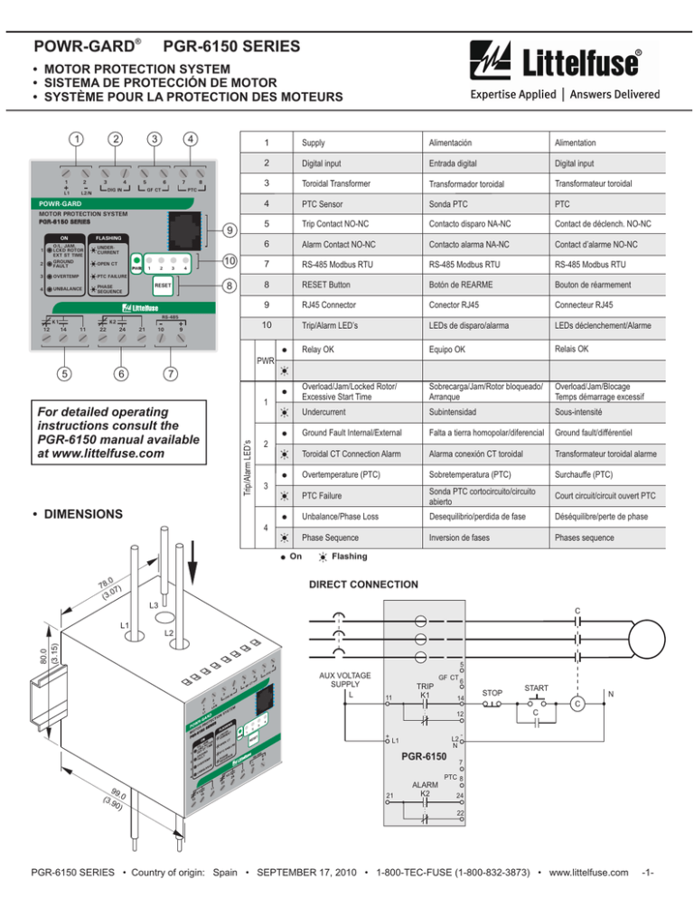
POWR-GARD ® PGR-6150 SERIES • MOTOR PROTECTION SYSTEM • SISTEMA DE PROTECCIÓN DE MOTOR • SYSTÈME POUR LA PROTECTION DES MOTEURS 1 2 1 L1 2 3 3 4 5 DIG IN L2/N 4 6 7 1 Supply Alimentación Alimentation 2 Digital input Entrada digital Digital input 3 Toroidal Transformer Transformador toroidal Transformateur toroidal 4 PTC Sensor Sonda PTC PTC 5 Trip Contact NO-NC Contacto disparo NA-NC Contact de déclench. NO-NC 6 Alarm Contact NO-NC Contacto alarma NA-NC Contact d’alarme NO-NC 10 7 RS-485 Modbus RTU RS-485 Modbus RTU RS-485 Modbus RTU 8 8 RESET Button Botón de REARME Bouton de réarmement 9 RJ45 Connector Conector RJ45 Connecteur RJ45 10 Trip/Alarm LED’s LEDs de disparo/alarma LEDs déclenchement/Alarme Relay OK Equipo OK Relais OK Overload/Jam/Locked Rotor/ Excessive Start Time Sobrecarga/Jam/Rotor bloqueado/ Arranque Overload/Jam/Blocage Temps démarrage excessif Undercurrent Subintensidad Sous-intensité Ground Fault Internal/External Falta a tierra homopolar/diferencial Ground fault/différentiel Toroidal CT Connection Alarm Alarma conexión CT toroidal Transformateur toroidal alarme Overtemperature (PTC) Sobretemperatura (PTC) Surchauffe (PTC) PTC Failure Sonda PTC cortocircuito/circuito abierto Court circuit/circuit ouvert PTC Unbalance/Phase Loss Desequilibrio/perdida de fase Déséquilibre/perte de phase Phase Sequence Inversion de fases Phases sequence 8 PTC GF CT POWR-GARD MOTOR PROTECTION SYSTEM PGR-6150 SERIES ON 1 2 O/L, JAM, LCKD ROTOR EXT ST TIME GROUND FAULT UNDERCURRENT OPEN CT PWR 3 OVERTEMP PTC FAILURE 4 UNBALANCE PHASE SEQUENCE K1 12 9 FLASHING 1 2 11 22 4 RESET RS-485 K2 14 3 24 21 10 9 PWR 6 7 For detailed operating instructions consult the PGR-6150 manual available at www.littelfuse.com 1 Trip/Alarm LED’s 5 2 3 • DIMENSIONS 4 On .0 78 7) 0 (3. Flashing DIRECT CONNECTION L3 C L1 80.0 (3.15) L2 5 AUX VOLTAGE SUPPLY L GF CT 11 TRIP K1 6 14 12 + L2 N L1 PGR-6150 99 (3. .0 90 ) 21 ALARM K2 STOP START N C C - 7 PTC 8 24 22 PGR-6150 SERIES • Country of origin: Spain • SEPTEMBER 17, 2010 • 1-800-TEC-FUSE (1-800-832-3873) • www.littelfuse.com -1- POWR-GARD ® PGR-6150 SERIES • MOTOR PROTECTION SYSTEM • SISTEMA DE PROTECCIÓN DE MOTOR • SYSTÈME POUR LA PROTECTION DES MOTEURS EXTERNAL CT CONNECTION CT1 ATTENTION: To prevent electrical shock, disconnect the power source before installing or servicing. Check that the auxiliary voltage supply is correct. Installation with frequency inverters: s Set IB at ~ 1.3 x IN s The PGR-6150 or current transformers should be connected on the line side of the inverter. In a wye-delta starter the relay or current transformers must be installed on the line side of the contactor. Do not use automatic reset mode in applications where an automatic motor start can cause injury to persons or damage to equipment. For PTC connection lengths over 100 m (328’), or when high transient voltages are expected, use shielded cable and connect the shield to ground. C CT2 CT3 5 AUX VOLTAGE SUPPLY L ATENCIÓN: Para evitar descargas eléctricas durante la instalación o manipulación del relé, asegúrese de que no hay tensión en la linea. Comprobar que la tensión auxiliar de alimentación es la correcta. Instalación con convertidores de frecuencia: no conectar el relé o los trasformadores de intensidad ni la alimentación auxiliar del relé a la salida del convertidor y ajustar IB a 1.3 x IN aprox. En arranque estrella-triángulo se debe instalar el relé o los tranformadores de intensidad entre los fusibles o automático y el contactor de linea. No usar el modo de reset automático donde el rearranque repentino del motor pueda causar daños a las personas o al equipo protegido. Para longitudes de conexión de la sonda PTC superiores a 100 metros (328’), o cuando se prevea la influencia de tensiones transitorias de alta frecuencia, se recomienda utilizar cable apantallado y conectar la malla de blindaje a tierra. GF CT 6 11 TRIP K1 14 STOP L2 N L1 PGR-6150 21 ALARM K2 N C C 12 + START - 7 PTC 8 24 22 PTC AND GROUND FAULT CONNECTION GF CT C +t 5 GF CT 6 AUX VOLTAGE SUPPLY L 11 TRIP K1 14 12 + L1 21 PGR-6150 ALARM K2 L2 N 7 PTC 8 24 22 STOP START N C C ATTENTION: Avant le montage et la mise en service, coupez l’alimentation secteur pour éviter toute décharge. Vérifiez que la tension auxiliare d’alimentation est correcte. L’installation avec variateurs de fréquences: Ne pas branchez le relais, les transformateurs d’intensité, ni la alimentation du relais après le variateur et réglez la IB à 1.3 x IN approx, Avec démarreur étoile-triangle, le relais ou les transformateurs d’intensité doivent être installés entre les fusibles ou le disjoncteur et le contacteur de la ligne. N’utilisez pas le mode réarmement automatique dans les applications où un redémarrage automatique inattendu du moteur pourrait provoquer des blessures personnelles ou des dégats matériels. Pour des longueurs de branchement PTC superieures à 100 mètres (328’), ou lorsque l’influence des tensions transitoires à haute fréquence est prévue, il est conseillé d’utiliser du câble blindé et de connecter la maille du blindage à Terre. PGR-6150 SERIES • Country of origin: Spain • SEPTEMBER 17, 2010 • 1-800-TEC-FUSE (1-800-832-3873) • www.littelfuse.com -2- POWR-GARD ® PGR-6150 SERIES • MOTOR PROTECTION SYSTEM • SISTEMA DE PROTECCIÓN DE MOTOR • SYSTÈME POUR LA PROTECTION DES MOTEURS • TRIP CURVES t(s) • CURVAS DE DISPARO t(s) Overload (cold) • COURBES DE DÉCLENCHEMENT t(s) Overload Class 10 10,000 10,000 10,000 1,000 1,000 1,000 TRIP CLASS 5 10 15 20 25 30 35 40 45 100 COLD HOT 60% HOT 75% 100 Overload Class 20 COLD HOT 60% HOT 75% 100 45 30 20 10 10 10 10 HOT 60% I = 0.9 IB HOT 75% I = IB HOT 60% I = 0.9 IB HOT 75% I = IB 1 0 1 2 3 4 1.15 IB 5 6 7 8 x IB 1 9 10 11 0 1 2 3 4 1.15 IB 5 6 7 x IB 8 9 10 11 1 0 1 2 3 4 1.15 IB 5 6 7 x IB 8 9 10 11 • SETTINGS Minimum Setup for Overload Protection* SETTING [Menu Path] Default Without External Phase CT’s (< 25 A motors) Nominal current (IB) [Settings/General] 4 Motor Full Load Current (IN) CT Turns Ratio [Settings/General] 1 1 Trip Class [Settings/General/Overload] 5 Motor Trip Class (s at 7x IN) With External Phase CT’s IN ÷ CT-Primary (A) x CT-Secondary CT-Primary (A) ÷ CT-Secondary Motor Trip Class (s at 7x IN) *See Settings Table for a complete list. PGR-6150 SERIES • Country of origin: Spain • SEPTEMBER 17, 2010 • 1-800-TEC-FUSE (1-800-832-3873) • www.littelfuse.com -3- POWR-GARD ® PGR-6150 SERIES • MOTOR PROTECTION SYSTEM • SISTEMA DE PROTECCIÓN DE MOTOR • SYSTÈME POUR LA PROTECTION DES MOTEURS • CHANGING SETTINGS • MODO DE AJUSTE • ACCÈS AUX PARAMÈTRES • The PGR-6150 Motor Protection System can be programmed using a remote computer or SCADA system connected to the RS-485 port, or with a PGR-6150-OPI Operator Interface connected to the RJ45 port.. • Para acceder a la configuración el PGR-6150 es necesario hacerlo a traves de un SCADA o bien del PGR-6150-OPI conectado a través del conector RJ45. • Pour accèder aux paramètres du PGR-6150, il est nécessaire de le faire bien au travers d’un système SCADA bien avec l’interface PGR-6150-OPI, connecté au RJ45. Menu translation / Traducción del menu / Menu Traduction States Estados États Metering Medidas Mesures Settings Ajustes Réglage Settings General Ajustes generales Réglages généraux Nominal current Corriente nominal Intensité nominal Password Clave Mot de passe Confirm setting Confirmar ajustes Conrirmer réglage Yes / no Si / no Oui / non Settings changed Ajuste modificado Réglages modifiés CT Turns Ratio Relacion de CT Relation TI Overload Ajustes sobrecarga Réglage surcharge Pickup Toma Tap Trip Class Clase de disparo Courbe déclenchement MOTOR PROTECTION SYSTEM POWER OVERTEMP O/L, JAM, LCKD ROTOR, EXT ST TIME UNBALANCE, PHASE SEQUENCE GROUND FAULT OPEN CT, PTC FAILURE UNDERCURRENT PWR 1 2 3 4 RESET The keys «, ½, ¬, and Ñ are used to navigate through the different options and menus. The “OK” key is used to accept changes and to enter a menu or an option. The “C” key is used to move up through the menu levels. A password is not required to view parameters, measurements or settings... A 4 character password must be entered to modify settings. Once the password has been entered from the PGR-6150-OPI, a 5 minute session is established. After this time the password must be entered again to execute password-protected operations. The default password is 5555. To navigate from one item to another within a parameter use the ¬ and Ñ keys. To increase or decrease values use the « and ½ keys. To test LED’s on both the base and OPI module press the “RESET” key once. To reset latched trips press and hold the “RESET” key . To stop the motor press the “O” key, this will result in a trip condition. To use the motor start function “I” a PGA-0180 Input/Output module is required. • The following demonstrates the sequence of steps to adjust the settings to protect a 100 A, Class 20 motor with a 1.15 service factor and 75:5 phase CTs connected as shown in the diagram “External CT Connection”. • Ajustes necesarios para proteger un motor de 100 A, con los transformadores de intensidad 75:5, de acuerdo al ejemplo de conexión “External CT Connection”. • Réglages nécessaires pour protéger un moteur de 100 A, avec les TI 75:5, selon l’example de connexion “External CT Connection”. PGR-6150 POWR-GARD OK PGR-6150 STATES PGR-6150 METERING PGR-6150 SETTINGS x6 NOMINAL CURRENT (A) 4.00 OK SETTINGS GENERAL OK x6 Password: O*** Password: 5*** Password: 555* Password: 555O x6 Password: 55O* OK Password: 5O** Password: 55** x6 Password: 5555 OK NOMINAL CURRENT (A) 004.00 3s NOMINAL CURRENT (A) 006.70 OK Confirm setting yes OK Settings changed OK OK NOMINAL CURRENT (A) 6.70 CT TURNS RATIO 1 OK 3s CT TURNS RATIO 00001 CT TURNS RATIO 00015 SETTINGS GENERAL SETTINGS OVERLOAD TRIP CLASS O TRIP CLASS 20 OK OK Confirm setting yes OK FUNCTION ENABLED yes Settings changed OK OK SERVICE FACTOR (xIB) 1.15 CT TURNS RATIO 15 TRIP CLASS 5 C OK 3s OK Confirm setting yes OK Settings changed OK OK TRIP CLASS 20 PGR-6150 SERIES • Country of origin: Spain • SEPTEMBER 17, 2010 • 1-800-TEC-FUSE (1-800-832-3873) • www.littelfuse.com -4- POWR-GARD ® PGR-6150 SERIES • MOTOR PROTECTION SYSTEM • SISTEMA DE PROTECCIÓN DE MOTOR • SYSTÈME POUR LA PROTECTION DES MOTEURS • SCADA CONNECTION • CONEXION A SCADA The PGR-6150 has an RS-485 port to communicate with a remote computer or a SCADA system. It uses Modbus RTU protocol (19,200 -8 bit - no parity -1 stop bit). See manual at www.littelfuse.com. • CONNECTION SCADA PGR-6150 PGR-6150 RS-485 + 9 10 PGR-6150 RS-485 + 9 10 RS-485 + 9 10 Up to 32 devices can connect to the same bus, each with a different Modbus address. The Modbus address of the relay is configured with the PGR-6150-OPI. To minimize communication errors due to noise, use shielded cable. Observe polarity ie. + terminals connect to +, etc. For very long cables, use resistors at each end of the cable. The resistor value should be equal to the impedance of the cable. C R El relé PGR-6150 dispone de un puerto RS-485 para comunicarse con un ordenador remoto ó un sistema SCADA de manera continua. El protocolo utilizado es Modbus RTU (19,200 -8bit - sin paridad - 1bit stop). Ver manual en www.littelfuse.com. R C + - G RS-485/ RS-232 RS-232 El puerto RS-485 sale al exterior por dos bornas (+ y -). Pueden conectarse hasta 32 equipos a un mismo bus; cada uno con una dirección Modbus diferente. La dirección Modbus del equipo se configura desde el PGR-6150-OPI. Para minimizar errores de comunicación por ruido, se recomienda utilizar un cable trenzado apantallado como medio fisico. Para realizar la conexión, deben conectarse todas las bornas + por un lado y todas las - por otro. Es necesario utilizar resistencias en cada extremo en caso de utilizar cables muy largos. La mejor solución para evitar la reflexión es colocar resistencias en ambos extremos del cable. El valor de estas resistencias deberá ser el mismo que la impedancia característica del cable. Le relais PGR-6150 a un port RS-485 pour communiquer avec un ordinateur ou d’un système SCADA sur une base continue. Le protocole utilisé est Modbus RTU (19,200 -8 bit - sans parité - 1 bit d’arrêt). Voir le manuel www.littelfuse.com. Le port RS-485 correspond à deux bornes (+ et -). Il est possible de connecter jusqu’à 32 appareils sur le même bus, chacun avec une adresse Modbus différente. L’adresse Modbus de l’appareil est configuré en utilisant le PGR-6150-OPI. Afin de minimiser les erreurs de communication par le bruit, l’utilisation de câble bindé. Pour établir la connexion, vous devez vous connecter tous les terminaux d’un côté, + et - pour toutes les autres. Il est nécessaire d’utiliser des résistances à chaque extrémité, si vous utilisez des câbles très longs. La meilleure solution pour éviter la réflection est de mettre résistances sur les deux extrémités du câble. La valeur de ces résistances doit être la même que l’impedance caractéristique du câble. TECHNICAL DATA DATOS TÉCNICOS DONNÉES TECHNIQUE Maximum motor voltage Maxima tension del motor Tension maximum du moteur PTC minimum cold resistance PTC resistencia minima en frio PTC: Résistance minimum à froid Max. cold resistance of PTC in series PTC average trip resistance/ reset resistance Terminal section PTC resistencia max. en frio de sondas en serie PTC resistancia media de disparo/ rearme Sección para embornar maximo PTC: Résistance Max. á froid de sondes en série PTC: Résistance moyenne de déclenchement/réarmement Screw torque Par Max. de apriete Couple max. de serrage Power consumption Consumo Puissance consommée <5W 5 Section terminaux 1,000 V 50 W 1,500 W 3,600/1,800 W 2.5 mm2 (22-12 AWG) 0.2 N-m (1.8 in.lb) Electrical life Vida électrica Vie électrique 5 x 10 Operations Mechanical life Vida mecánica Vie mécanique 106 Operations Storage temperature Temperatura de almacenaje Temperature de stockage -20 to 70°C Operational temperature/ maximum altitude Output contacts Temperatura de utilización/ Altitud máxima Contactos de salida Temperature d’opération/ Altitude maximum -10 to 60°C/3,000 m (9,800’) Contact de sortie Standards Normas Normes 250 Vac - 8 A 30 Vdc - 8 A EN 50263 (1999), EN 61000-6-4 (2001) EN 61000-6-2 (2001), EN 55011 Y EN 55022, IEC 61000-4 IEC 60255-22-1, IEC 255, IEC 947-4-1 PGR-6150 SERIES • Country of origin: Spain • SEPTEMBER 17, 2010 • 1-800-TEC-FUSE (1-800-832-3873) • www.littelfuse.com -5- SETTINGS General General Nominal Current CT Turns Ratio (2*) Frequency Motor Start Limit Motor Starting Time Phase Sequence PGR-6150 Initial Time Overload Function Enabled Service Factor Trip Class External Ventilation Alarm Unbalance Function Enabled Unbalance % Starting Trip Time Running Trip Time Phase Loss Function Enabled Unbalance % Time (Operating time) Sequence Function Enabled Time (Operating time) PTC Sensor Function Enabled Jam Function Enabled Pickup Time (Operating time) Locked Rotor Function Enabled Pickup Time (Operating time) I0>> GF Calculated Definite time Function Enabled Pickup Time (Operating time) I0> GF Calculated Inverse Time Function Enabled (1*) Curve Dial Pickup Time (Operating time) IG>> GF Measured Definite Time Function Enabled Pickup Time (Operating time) IG> GF Measured Inverse Time Function Enabled (1*) Curve Dial Pickup Time (Operating time) I< (Undercurrent) Function Enabled Pickup Time (Operating time) Communication (4*) Modbus address Reset Enable OPI Enable Network Enable input (3*) Reset type Reset time (1*) (2*) (3*) (4*) CARACTERISTICAS TECNICAS Generales Intensidad nominal Relación CT (2*) Frecuencia Umbral arranque motor Tiempo arranque motor Secuencia fases motor Temporizatión inicio equipo Sobrecarga Permiso Toma Clase disparo Ventilación independiente Alarma Desequilibrio Permiso % desequilibrio Tiempo motor arrancando Tiempo motor marche Fallo de fase Permiso % Fallo de fase Tiempo operación Inversion Permiso Tiempo operación Sonda PTC Permiso Jam Permiso Toma Tiempo operación Rotor bloqueado Permiso Toma Tiempo operación Falta a tierra homopolar tiempo definido Permiso Toma Tiempo operación Falta a tierra homopolar tiempo inverso Permiso (1*) Curva Dial Toma Tiempo operación Falta a tierra diferencial tiempo definido Permiso Toma Tiempo operación Falta a tierra diferencial tiempo inverso Permiso (1*) Curva Dial Toma Tiempo operación Subintensidad Permiso Toma Tiempo operación Comunicación (4*) Dirección Modbus Rearme Permiso rearme OPI Permiso rearme comando Permiso rearme entrada (3*) Tipo rearme Tiempo rearme Curves Inverse, very inverse, extremely inverse and definite time. Frequency can be adjusted for 50 Hz, 60 Hz and variable. Variable range is from 45 to 65 Hz, and applies only to models with alternating supply voltage. Reset type are: Automatic, Manual and Automatic Time Delay. The Modbus address can be changed with the PGR-6150-OPI. The rest of the settings can be changed with the PGR-6150-OPI and from communications. (1*) (2*) (3*) (4*) Min. CARACTERISTIQUE TECHNIQUES Générales Intensité nominal 4 Relation TI 1 (2*) Fréquence Limite démarrage moteur 1 Temps démarrage 1 Ordre des phases Temporisation au démarrage 0 Surcharge Permission Tap 1 Courbe déclenchement Ventilation externe Alarme 20 Déséquilibre Permission 5 % déséquilibre 0.02 Temps de Démarrage 0.02 Temps de fonctionnement Perte de phase Permission 10 % Perte de phase 0.02 Temps d’opération Séquence Permission Temps d’opération 0.02 PTC Permission Jam Permission 1 Tap 0.02 Temps d’opération Rotor Bloqué Permission 3.5 Tap 1 Temps d’opération Défaut de neutre temps constant Permission Tap 0.1 0.02 Temps d’opération Défaut de neutre temps inverse Permission (1*) Courbe 0.05 Dial 0.1 Tap Temps d’opération 0.02 Défaut differential fuite à terre temps constant Permission 100 Tap 0.02 Temps d’opération Défaut differential fuite à terre temps inverse Permission (1*) Courbe 0.05 Dial 100 Tap Temps d’opération 0.02 Sous-intensité Permission 0.3 Tap 0.02 Temps d’opération Communication (4*) Adresse Modbus 1 Réarmement Autorisation réarmement OPI Autorisation réarme command Autorisation reset input (3*) Mode réarmement 0.02 Temps réarmement Curvas inversa, muy inversa, extremadamente inversa y tiempo definido. La frecuencia puede ajustarse a los valores de 50 Hz, 60 Hz y frecuencia variable en el rango de 45 a 65 Hz. La frecuencia variable solo puede aplicarse a los modelos con tension de alimentacion alterna. Los tipos de rearme son: automatico, automatico temporizado y manual. El ajuste Dirección modbus solo puede modificarse desde el PGR-6150-OPI. El resto de los ajustes puede modificarse desde el PGR-6150-OPI y desde comunicaciones. (1*) (2*) (3*) (4*) Max. Step Unit Default 25 2,000 8 200 3,600 0.01 1 50 Hz/60 Hz/Variable 0.01 1 ABC/ACB 1 A x IB s s 4 1 50 Hz 1.5 60 ABC 0 2 95 Yes/No 0.01 5, 10, 15, 20, 25, 30, 35, 40, 45 Yes/No 1 x IB % Yes 1.15 5 No 80 30 20 20 Yes/No 1 0.001 0.001 % s s Yes 30 0.6 5 100 20 Yes/No 1 0.001 % s Yes 30 5 2 Yes/No 0.001 s No 0.02 - Yes/No - No 3.5 50 Yes/No 0.01 0.001 x IB s No 2.5 10 6 30 Yes/No 0.01 0.001 x IB s No 3.5 5 1 5 Yes/No 0.01 0.001 x IB s No 0.1 1 1.25 1 5 Yes/No Def/Inv./Very Inv./Ext. Inv 0.01 0.01 0.001 x IB s No Inversa 1.25 1.00 0.2 15,000 5 Yes/No 1 0.001 mA s No 100 0.2 1.25 450 5 Yes/No Def/Inv./Very Inv./Ext. Inv 0.01 1 0.001 mA s No Inversa 1.25 100 0.2 1 200 Yes/No 0.01 0.001 x IB s No 0.5 1 255 1 - 1 200 Yes/No Yes/No Yes/No Auto/Auto Time Delay/Manual 0.001 s No No No Manual 0.1 Courbes inverse, très inverse, extrêmement inverse et temps constant. La fréquence peut être ajustée pour les valeurs de 50 Hz, 60 Hz et fréquence variable dans la gamme de 45 to 65 Hz. La fréquence variable est applicable que pour des modèles avec alimentation à courant alternatif. Les modes de réinitialisation sont automatique, manuel et automatique avec temporisation. L’adresse modbus ne peut être modifié que depuis le PGR-6150-OPI. Le reste des paramètres peuvent être modifiés depuis le PGR-6150-OPI ou via communications.
