SCR SWITCHED CAPACITOR VAR COMPENSATION cosφ= P S S
Anuncio
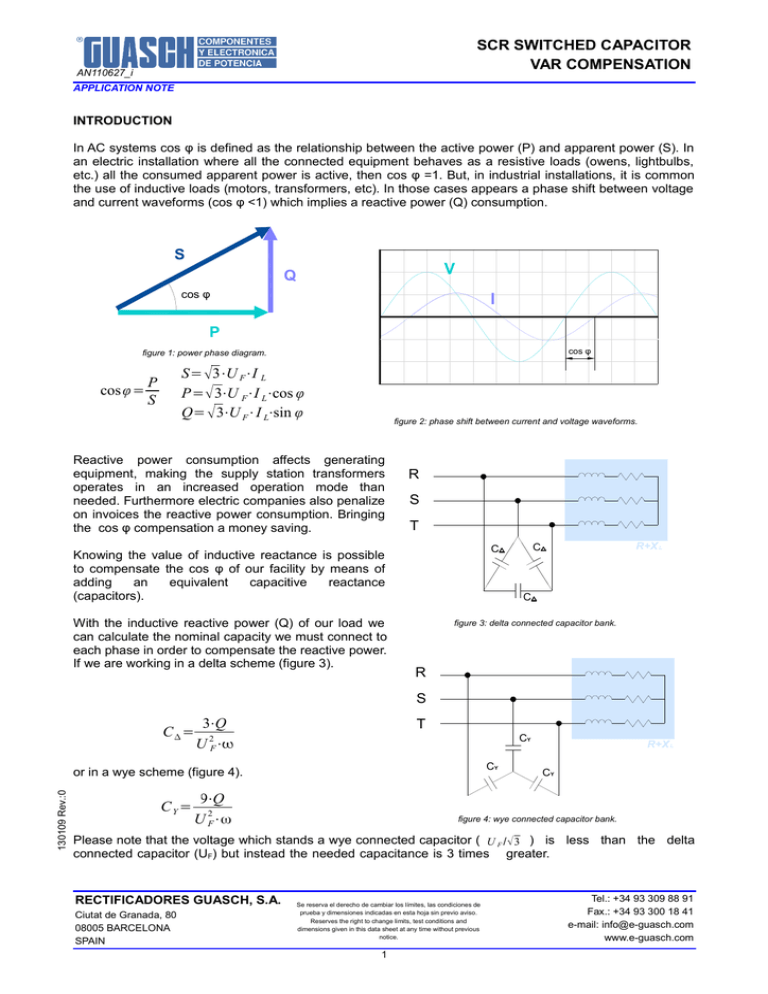
SCR SWITCHED CAPACITOR VAR COMPENSATION AN110627_i APPLICATION NOTE INTRODUCTION In AC systems cos φ is defined as the relationship between the active power (P) and apparent power (S). In an electric installation where all the connected equipment behaves as a resistive loads (owens, lightbulbs, etc.) all the consumed apparent power is active, then cos φ =1. But, in industrial installations, it is common the use of inductive loads (motors, transformers, etc). In those cases appears a phase shift between voltage and current waveforms (cos φ <1) which implies a reactive power (Q) consumption. S V Q cos φ cos I P cos cos φ figure 1: power phase diagram. cos φ= S= 3⋅U F⋅I L P= 3⋅U F⋅I L⋅cos φ Q= 3⋅U F⋅I L⋅sin φ P S figure 2: phase shift between current and voltage waveforms. Reactive power consumption affects generating equipment, making the supply station transformers operates in an increased operation mode than needed. Furthermore electric companies also penalize on invoices the reactive power consumption. Bringing the cos φ compensation a money saving. R S T With the inductive reactive power (Q) of our load we can calculate the nominal capacity we must connect to each phase in order to compensate the reactive power. If we are working in a delta scheme (figure 3). R+X L C C Knowing the value of inductive reactance is possible to compensate the cos φ of our facility by means of adding an equivalent capacitive reactance (capacitors). C figure 3: delta connected capacitor bank. R S C= 3⋅Q 2 U F⋅ T CY CY 130109 Rev.:0 or in a wye scheme (figure 4). CY= 9⋅Q U 2F⋅ω R+X L CY figure 4: wye connected capacitor bank. Please note that the voltage which stands a wye connected capacitor ( U F / √ 3 ) is less than the delta connected capacitor (UF) but instead the needed capacitance is 3 times greater. RECTIFICADORES GUASCH, S.A. Ciutat de Granada, 80 08005 BARCELONA SPAIN Se reserva el derecho de cambiar los límites, las condiciones de prueba y dimensiones indicadas en esta hoja sin previo aviso. Reserves the right to change limits, test conditions and dimensions given in this data sheet at any time without previous notice. 1 Tel.: +34 93 309 88 91 Fax.: +34 93 300 18 41 e-mail: info@e-guasch.com www.e-guasch.com AN110627_i APPLICATION NOTE CAPACITOR BANK DYNAMIC CONNECTION However it is very likely that the cos φ of our facility varies thorough the day because machines connection/disconnection, start and stop engine, etc. A cos φ change implies a variation in our capacitor bank, a way to do that is to measure the phase shift and act with contactors in order to switch on or off capacitor groups. These contactors can be static (semiconductor) or electromechanical The second one have several drawbacks: delayed switching between the switch signal and the proper switch (tricky to synchronize with the power mains) and also due its mechanical behavior, rebounds occur in the contact which is a source of electrical noise and contact (and device) degradation. R S T CA CA CA CB CB CB figure 5: connection using SCRs of a capacitor bank in wye (a) and delta (b) schemes. Although the capacitive reactive power consumption is not penalized, to have more capacity than the strictly necessary connected in the network, is an unnecessary power consumption. figure 6: Solid state vs. electromechanical relay waveforms. 130109 Rev.:0 ZERO-CROSS SWITCH STATIC CONTACTOR Using the zero-cross switching cards SC018, SC024 and SC030 it is possible to make a simple galvanic isolated estatic contactor controlling two SCRs in antiparallel (W1C configuration). Model choosing depends of the mains working voltage and the capacitor configuration: RECTIFICADORES GUASCH, S.A. Ciutat de Granada, 80 08005 BARCELONA SPAIN Se reserva el derecho de cambiar los límites, las condiciones de prueba y dimensiones indicadas en esta hoja sin previo aviso. Reserves the right to change limits, test conditions and dimensions given in this data sheet at any time without previous notice. 2 Tel.: +34 93 309 88 91 Fax.: +34 93 300 18 41 e-mail: info@e-guasch.com www.e-guasch.com AN110627_i datasheet U working [V] U max [Vpk] SC018 400 1800 SC024 480 2400 SC030 690 3000 G2 ON-state LED K2 control signal GND K1 VCC G1 isolation barrier SC0XX W1C figure 7: zero-switch static relay with an SC0XX card. When a switching signal is applied to card's input control, the SCRs will switch when the voltage across its terminals crosses the 0 V. The switch off is produced naturally when the control signal is off and the direct current flowing through SCRs extinguishes. The internal operation of the card is as follows: The switching of the SCRs is made by connecting the anode to the gate (through a resistor) This method ensures correct firing of the thyristor, as the trigger energy obtained from the same power circuit. And it is also very robust, no additional power supply required, just a simple trigger signal with a maximum consumption of 30 mA. The connection of capacitor banks in the zero-cross voltage, minimizes the initial current peak which causes variation of voltage across the capacitor, extending its life and preventing voltage drops occur in the network due to wiring inductances. TOPOLOGIES As we have seen, the capacitors can be connected in different ways in three-phase installations. We can even choose to have a phase always connected while we control the other two. Here are some options: R R S S T T 130109 Rev.:0 C C C C figure 8: W3C contactor, wye connected capacitors. RECTIFICADORES GUASCH, S.A. Ciutat de Granada, 80 08005 BARCELONA SPAIN C C figure 9: W3.2C contactor, wye connected capacitors. Se reserva el derecho de cambiar los límites, las condiciones de prueba y dimensiones indicadas en esta hoja sin previo aviso. Reserves the right to change limits, test conditions and dimensions given in this data sheet at any time without previous notice. 3 Tel.: +34 93 309 88 91 Fax.: +34 93 300 18 41 e-mail: info@e-guasch.com www.e-guasch.com AN110627_i APPLICATION NOTE R R S S T T C C C C figure 10: W3C contactors, delta connected capacitors. C C figure 11: contactors W3.2C , delta connected capacitors. W3.2C configuration in front of W3C represents a cost saving, since it requires only two contactors per bank. R S The drawback, you can't use a wye connection with neutral because one of the capacitors will allways be connected. T We must also consider the voltage drop in each thyristor group when turned off. In all of them the voltage across SCRs will be UF, The SCR choice should be made taking into account the maximum voltage difference if the capacitors are not discharged quickly enough: C C C U PK =2⋅ 2⋅U F Then, for a three phase mains with 230 VAC between phases, UPK = 650 V, a 1200 VRRM thyristor is recommended. figure 12: inside delta contactors. Following the same procedure: 130109 Rev.:0 400 VAC → UPK=1131V, 1600 VRRM or 1800 VRRM SCR. 480 VAC → UPK=1357V, 2200 VRRM SCR. 690 VAC → UPK=1951V, 3300 VRRM SCR. Another phenomena also appears when shooting contactors sequentially during its zero-cross, and is that in the instant a contact is closed (in W3.2C) or 2 closing contacts (in W3C) and before the final closing, the branches leading directly affect the other creating phase changes in voltage across the contactor and floating branch conduction (please see figure 13). All of these effects are undesirable and can be avoided using the configuration inside delta contactors (figure 14). RECTIFICADORES GUASCH, S.A. Ciutat de Granada, 80 08005 BARCELONA SPAIN Se reserva el derecho de cambiar los límites, las condiciones de prueba y dimensiones indicadas en esta hoja sin previo aviso. Reserves the right to change limits, test conditions and dimensions given in this data sheet at any time without previous notice. 4 Tel.: +34 93 309 88 91 Fax.: +34 93 300 18 41 e-mail: info@e-guasch.com www.e-guasch.com AN110627_i V_ W1C_a V_ W1C_b V_W1C_c 20 0 10 0 0 -100 -200 Phase shift -300 I(C31a ) I(C3 1b) I(C31c) 6 Floating branch conduction 4 2 0 -2 -4 -6 0 0.0 1 0.02 0.03 T im e (s) 0 .04 0.05 0.06 figure 13: contactor voltage (up) and current flowing through capacitiors (down) wye W3C topology. V_W1 C_ a V_ W1C_b V _W1 C_ c 40 0 20 0 0 -20 0 -40 0 I(C31a ) I(C31b) I(C31 c) 15 10 5 0 -5 130109 Rev.:0 -1 0 -1 5 0 0 .01 0 .02 0.03 T im e (s) 0.04 0.05 0.06 figure 14: contactor voltage (up) and current flowing through capacitiors (down) inside delta contactors topology. RECTIFICADORES GUASCH, S.A. Ciutat de Granada, 80 08005 BARCELONA SPAIN Se reserva el derecho de cambiar los límites, las condiciones de prueba y dimensiones indicadas en esta hoja sin previo aviso. Reserves the right to change limits, test conditions and dimensions given in this data sheet at any time without previous notice. 5 Tel.: +34 93 309 88 91 Fax.: +34 93 300 18 41 e-mail: info@e-guasch.com www.e-guasch.com AN110627_i APPLICATION NOTE MOUNTING RECOMMENDATIONS Fuses: They are essential to protect the installation. They must be connected in series with each contactor to better match the current value of the fuse with the branch that protects. Connecting a single fuse with several branches (with banks with a lot of branches and capacitors) makes it necessary to increase the current of the fuse leading a less effective protection. Inductance ballast: Inductive reactances should be connected with the branches of the capacitor banks when we have nonlinear loads in our facility. Nonlinear loads produces harmonics (multiple frequency of the mains). A bank of capacitors is a purely capacitive load of low impedance for high frequency currents and these currents can cause overheating of the capacitor and premature aging. In addition to putting a capacitor, along with the rest of the circuit inductance, can lead the circuit into resonance with one of the harmonics and cause a catastrophic failure. Put properly calculated ballasts banks softens these effects. Choosing thyristors: First, you must take into account the voltage criteria described before in topologies paragraph. Then we must bear in mind that a thyristor with a higher current value also have a higher latching and maintenance currents, this delays the triggering for low working currents, can also be more noisy or even will be impossible to trigger on. (figure 15). figure 15: capacitor voltage (left) and contactor voltage (right) for a deficient triggering due a lack of current. 130109 Rev.:0 It is important to adjust the SCR nominal slightly upwards the working current will circulate through them. But not oversize too much it if there is no cause. Delta connected capacitors I W1C =U F⋅⋅C Wye connected capacitors I W1C = UF ⋅⋅C 3 Delta-wye combinations Sometimes for large banks of capacitors is much more cost effective to have only one capacitance value and combine wye connected groups with delta connected groups, or even wye-delta associations, in order to obtain different values for different capacity and adjust the power factor correction. However it has the disadvantage that the previously mentioned effects of phase shift and floating branch conduction can be magnified. R S T C C C C C C figure 16: delta-wye combinations. RECTIFICADORES GUASCH, S.A. Ciutat de Granada, 80 08005 BARCELONA SPAIN Se reserva el derecho de cambiar los límites, las condiciones de prueba y dimensiones indicadas en esta hoja sin previo aviso. Reserves the right to change limits, test conditions and dimensions given in this data sheet at any time without previous notice. 6 Tel.: +34 93 309 88 91 Fax.: +34 93 300 18 41 e-mail: info@e-guasch.com www.e-guasch.com AN110627_i Combinations with electromechanic relays You can combine the use of electromechanical relays with static relay where is contemplated that the added noise produced by electromechanical relays do not affect the proper operation of static contactors and other circuit elements. It is much more advisable to use a single type of relays, preferably static ones. Discharge resistors It should connect a discharge resistors in each capacitor of the capacitor bank. These resistors ensure that the capacitor is fully discharged when starting the contactor and discharged quickly when it is open again. RECOMMENDED APPLICATION CIRCUIT For all that described before in this document the following is the application circuit recommended by Rectificadores GUASCH, S.A. as a reactive compensation with a capacitor bank. R S T F F F F F F L L L L L L 130109 Rev.:0 C C C C C C figure 17: Recommended application circuit for VAR compensation. RECTIFICADORES GUASCH, S.A. Ciutat de Granada, 80 08005 BARCELONA SPAIN Se reserva el derecho de cambiar los límites, las condiciones de prueba y dimensiones indicadas en esta hoja sin previo aviso. Reserves the right to change limits, test conditions and dimensions given in this data sheet at any time without previous notice. 7 Tel.: +34 93 309 88 91 Fax.: +34 93 300 18 41 e-mail: info@e-guasch.com www.e-guasch.com AN110627_i APPLICATION NOTE ANOTACIONES EN LA NOTA DE APLICACIÓN: RECTIFICADORES GUASCH, S.A. utiliza la siguiente anotación para identificar el documento, en el lado izquierdo de la primera página: APPLICATION NOTE: La información contenida en esta publicación se refiere a aplicaciones de dispositivos y se proporciona solo para su conveniencia y puede ser sustituida por actualizaciones de la misma. Es su responsabilidad asegurar que su aplicación cumple con sus especificaciones. Los datos indicados en esta publicación pueden corresponder a especificaciones de producto, queda excluida cualquier garantía expresa o implícita sobre sus propiedades o su aplicación, así como cualquier responsabilidad sobre daños directos o indirectos producidos por los materiales o resultantes de su aplicación. La empresa se reserva el derecho de realizar cambios en las especificaciones de los productos sin previo aviso. La información respecto a métodos de uso y aplicaciones se indica sólo como guía y no constituye garantía alguna de funcionamiento satisfactorio en un determinado equipo o aplicación. Es responsabilidad del usuario determinar la idoneidad del producto para su aplicación utilizando la información disponible y asegurarse de que la misma esta actualizada. Cualquier nombre de producto o marca usada en esta publicación corresponde a marcas depositadas, marcas registradas o nombres protegidos por sus respectivos propietarios. APLICATION NOTE ANNOTATIONS: RECTIFICADORES GUASCH, S.A. annotate in the left corner of the front page to indicate the type of document: APPLICATION NOTE: Information contained in this publication regarding device applications and the like is provided only for your convenience and may be superseded by updates. It is your responsibility to ensure that your application meets with your specifications. The technical data are to specify components, not to guarantee their properties. No warranty or guarantee expressed or implied is made regarding delivery or performance. The Company reserves the right to alter without prior notice the specification of any product. Information concerning possible methods of use is provided as a guide only and does not constitute any guarantee that such methods of use will be satisfactory in a specific piece of equipment. It is the user’s responsibility to fully determine the performance and suitability of any equipment using such information and to ensure that any publication or data used is up to date. All brand names and product names used in this publication are trademarks, registered trademarks or trade names of their respective owners. © RECTIFICADORES GUASCH, S.A. DOCUMENTACION TECNICA, TECHNICAL DOCUMENTATION, DOCUMENTATION TECHNIQUE PRODUCIDO EN ESPAÑA, PRODUCED IN SPAIN, PRODUIT EN ESPAGNA PROHIBIDA SU VENTA, NOT FOR SALE, PAS A VENDRE 130109 Rev.:0 Your Needs, Our Solutions RECTIFICADORES GUASCH, S.A. Ciutat de Granada, 80 08005 BARCELONA SPAIN Se reserva el derecho de cambiar los límites, las condiciones de prueba y dimensiones indicadas en esta hoja sin previo aviso. Reserves the right to change limits, test conditions and dimensions given in this data sheet at any time without previous notice. 8 Tel.: +34 93 309 88 91 Fax.: +34 93 300 18 41 e-mail: info@e-guasch.com www.e-guasch.com
