Serie CS4P - Cirprotec
Anuncio

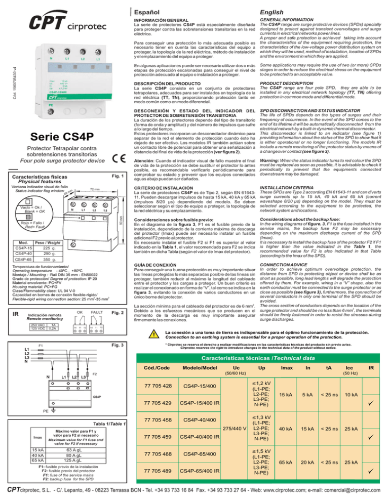
Cód. 1560705430 v4 Serie CS4P Protector Tetrapolar contra sobretensiones transitorias Four pole surge protector device Fig. 1 Características físicas Physical features Ventana indicador visual de fallo Status indicator flag window mm 72 mm 69 Vacío = Ok / Blank = OK N L1 L2 90 mm L3 Rojo = Fallo / Red= Fault Mod. PE Peso / Weight CS4P-15 CS4P-40 225 g. 290 g. CS4P-65 350 g. Temperatura de funcionamiento/ Operating temperature - 40ºC , +80ºC Montaje / Mounting : Rail DIN 35 mm - EN50022 Grado de protección/ Degree of protection: IP 20 Material envolvente: PC+FV Housing material: PC+FG Clase/Flammability class: UL 94 V-0 Capacidad en bornes de conexión flexible-rígido/ 2 2 Flexible-rigid wiring connection section: 25 mm -35 mm Español English INFORMACIÓN GENERAL La serie de protectores CS4P está especialmente diseñada para proteger contra las sobretensiones transitorias en la red eléctrica. Para conseguir una protección lo más adecuada posible es necesario tener en cuenta las características del equipo a proteger, la topología de la red eléctrica, método de instalación y el emplazamiento del equipo a proteger. GENERAL INFORMATION The CS4P range are surge protective devices (SPDs) specially designed to protect against transient overvoltages and surge currents in electrical networks power lines. A proper and safe protection is achieved taking into account the characteristics of the equipment requiring protection, the characteristics of the low-voltage power distribution system on which they will be used, method of installation, location of SPDs and the environment in which they are applied. En algunas aplicaciones puede ser necesario utilizar dos o más etapas de protección escalonadas para conseguir el nivel de protección adecuado al equipo o instalación a proteger. Some applications may require the use of two (or more) SPDs stages in order to reduce the electrical stress on the equipment to be protected to an acceptable value. DESCRIPCIÓN DEL PRODUCTO La serie CS4P consiste en un conjunto de protectores tetrapolares, adecuados para ser instalados en topología de la red eléctrica (TT, TN), proporcionando protección tanto en modo común como en modo diferencial. PRODUCT DESCRIPTION The CS4P range are four pole SPD, they are able to be installed in any electrical network topology (TT, TN) offering protection in common mode and differential mode. DESCONEXIÓN Y ESTADO DEL INDICADOR DEL PROTECTOR DE SOBRETENSIÓN TRANSITORIA La duración de los protectores depende del tipo de transitorio (forma de onda y amplitud) y del número de impulsos que sufre a lo largo del tiempo. Estos protectores incorporan un desconectador dinámico para separar de la red el elemento de protección cuando éste ha dejado de ser efectivo. Los modelos IR también actúan sobre un contacto libre de potencial para obtener una señalización a distancia del final de vida de la protección (ver figura 2). SPD DISCONNECTION AND STATUS INDICATOR The life of SPDs depends on the types of surges and their frequency of occurrence. In the event of the SPD comes to the end of its lifetime it will be automatically disconnected from the electrical network by a built-in dynamic thermal disconnector. This disconnector is linked to an indicator (see figure 1) providing information about the status of the SPD to show that it is either operational or no longer functioning. The models IR include a remote monitoring of the protector status by means of a changeover contact (see figure 2). Atención: Cuando el indicador visual de fallo muestre el final de vida de la protección se debe sustituir el protector lo antes posible, es recomendable verificarlo periódicamente para comprobar su estado y prevenir que los equipos conectados aguas abajo puedan ser dañados. Warning: When the status indicator turns to red colour the SPD must be replaced as soon as possible, it is advisable to check it periodically to prevent that the equipments connected downstream may be damaged. CRITERIO DE INSTALACIÓN La serie de protectores CS4P es de Tipo 2, según EN 6164311. Pueden descargar impulsos de hasta 15 kA, 40 kA y 65 kA (impulsos 8/20 µs) dependiendo del modelo. Se deben seleccionar según el tipo de equipo a proteger, la topología de la red eléctrica y su emplazamiento. INSTALLATION CRITERIA These SPDs are Type 2 according EN 61643-11 and can diverts surge currents up to 15 kA, 40 kA and 65 kA (current waveshape 8/20 µs) depending on the model. They must be selected according to the equipment to be protected, the network system and locations. Consideraciones sobre fusible previo: En el diagrama de la figura 3, F1 es el fusible previo de la instalación, dependiendo de la corriente máxima de descarga del protector (Imax) puede ser necesario instalar un fusible adicional F2 previo al protector. Es necesario instalar el fusible F2 si F1 es superior al valor indicado en la Tabla 1, el valor recomendado para F2 se indica también en dicha Tabla (según el valor de Imax del protector). Considerations about the backup fuse: In the wiring diagrams of figure. 3, F1 is the fuse installed in the service mains, the backup fuse F2 may be necessary depending on the maximum discharge current of the SPD (Imax). It is necessary to install the backup fuse of the protector F2 if F1 is higher than the value indicated in the Table 1, the recommended value for F2 is also indicated in that Table (according to the Imax of the SPD). GUÍA DE CONEXIÓN Para conseguir una buena protección es muy importante situar las líneas protegidas lo más separadas posible de las líneas sin proteger, también reducir al máximo la longitud del cableado entre el protector y las cargas a proteger. Un buen criterio es realizar el conexionado en forma de “V”, tal como se indica en la figura 3, evitando la conexión de varios conductores en un único borne del protector. CONNECTION ADVICE In order to achieve optimum overvoltage protection, the distance from SPD to protecting object or device shall be as short as possible, long lead lengths will degrade the protection offered by them. For example, wiring in a “V” shape, also the earth conductor must be connected to the surge protector or as close as possible (see figure 3), furthermore, the connection of several conductors in only one terminal of the SPD should be avoided. The cross section of conductors depends on the location of the 2 surge protector and should be no less than 6 mm , the terminals should be firmly fastened in order to resist the stresses during surge discharges. 2 IR OK Indicación remota Remote monitoring 250 VAC 125 VDC 1A 0,2A 14 11 FAULT 12 14 11 Fig. 2 La sección mínima para el cableado del protector es de 6 mm . Debido a los esfuerzos mecánicos que se producen en el momento de la descarga es muy importante asegurar firmemente las conexiones. 12 La conexión a una toma de tierra es indispensable para el óptimo funcionamiento de la protección. Connection to an earthing system is essential for a proper operation of the protection. Fig. 3 F1 L1 L2 L3 N * Cirprotec se reserva el derecho a realizar modificaciones en las características técnicas del producto sin previo aviso. Cirprotec reserves the right to introduce changes in the technical data of the product without notice. Características técnicas /Technical data Cód./Code N L1 L2 L3 Modelo/Model Uc Up Imax In tA (50/60 Hz) F2 77 705 428 CS4P-15/400 77 705 429 CS4P-15/400 IR 77 705 458 CS4P-40/400 77 705 459 CS4P-40/400 IR 77 705 488 CS4P-65/400 77 705 489 CS4P-65/400 IR CS4P Icc IR (50 Hz) £1,2 kV (L1-PE; L2-PE; L3-PE; N-PE) 15 kA 5 kA < 25 ns 10 kA £1,3 kV (L1-PE; L2-PE; L3-PE; N-PE) 40 kA 15 kA < 25 ns 25 kA £1,5 kV (L1-PE; L2-PE; L3-PE; N-PE) 65 kA 20 kA < 25 ns 25 kA PE Tabla 1/Table 1 Imax Máximo valor para F1 y valor para F2 si necesario Maximum value for F1 fuse and value for F2 if necessary 15 kA 40 kA 65 kA 63 A gL 80 A gL 125 A gL F1: fusible previo de la instalación F2: fusible previo del protector F1: fuse of the service mains F2: backup fuse for the SPD CPTcirprotec, S.L. 275/440 V - C/. Lepanto, 49 - 08223 Terrassa BCN - Tel. +34 93 733 16 84 Fax. +34 93 733 27 64 - Web: www.cirprotec.com; e-mail: comercial@cirprotec.com


