en otra ventana
Anuncio

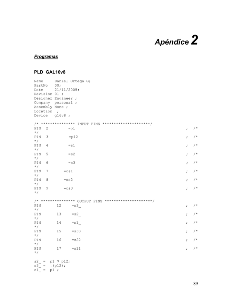
Apéndice 2 ; /* ; /* ; /* ; /* ; /* ; /* ; /* ; /* ; /* ; /* ; /* ; /* ; /* ; /* Programas PLD GAL16v8 Name PartNo Date Revision Designer Company Assembly Location Device Daniel Ortega G; 00; 21/11/2005; 01 ; Engineer ; personal ; None ; ; g16v8 ; /* *************** INPUT PINS *********************/ PIN 2 =p1 */ PIN 3 =p12 */ PIN 4 =s1 */ PIN 5 =s2 */ PIN 6 =s3 */ PIN 7 =os1 */ PIN 8 =os2 */ PIN 9 =os3 */ /* *************** OUTPUT PINS *********************/ PIN 12 =s3_ */ PIN 13 =s2_ */ PIN 14 =s1_ */ PIN 15 =s33 */ PIN 16 =s22 */ PIN 17 =s11 */ s2_ = s3_ = s1_ = p1 $ p12; !(p12); p1 ; 89 s11 = !(!(os3) & s1) ; s22 = !(!(os1) & s2) ; s33 = !(!(os2) & s3) ; PIC 16F877 ;============================================================================= ;============================================================================= ; Author: Daniel Ortega G. ; Company: UDLAP. ; Revision: 1.00 ; Date: 2005 ; Assembled using MPASMWIN V3.20 ;============================================================================= list p=16f877 ;list directive to define processor #include <p16f877.inc> ;processor specific definitions errorlevel -302 ;suppress "not in bank 0" message __CONFIG _CP_OFF & _WDT_OFF & _BODEN_OFF _LVP_OFF & _DEBUG_OFF & _CPD_OFF & _PWRTE_ON & _XT_OSC & _WRT_ENABLE_OFF & ;---------------------------------------------------------------------------;Bit Definitions flag adover adif adgo adie gie rp0 equ equ equ equ equ equ equ 10 0 1 2 6 7 5 ;----------------------------------------------------------------------------; Macros to select the register bank ; Many bank changes can be optimized when only one STATUS bit changes Bank0 Bank1 Bank2 Bank3 MACRO bcf bcf ENDM STATUS,RP0 STATUS,RP1 MACRO bsf bcf ENDM STATUS,RP0 STATUS,RP1 MACRO bcf bsf ENDM STATUS,RP0 STATUS,RP1 MACRO bsf bsf ;macro to select data RAM bank 0 ;macro to select data RAM bank 1 ;macro to select data RAM bank 2 ;macro to select data RAM bank 3 STATUS,RP0 STATUS,RP1 90 ENDM ;---------------------------------------------------------------------------;This code executes when a reset occurs. ORG ando dor prod_h prod_l ando_h conta equ equ equ equ equ equ 0x0000 ;place code at reset vector H'20' H'21' H'22' H'23' H'24' H'25' INDICE2 EQU 0X43 INDICE EQU 0X26 dd1 equ 0x27 dd2 equ 0x28 tmp equ 0x29 ddinA equ 0x30 m1 equ 0x31 m2 equ 0x32 baja equ 0x33 dda equ 0x34 dd2_ equ 0x35 ddinB equ 0x36 signo equ 0x37 off equ 0x38 regtmp equ 0x39 pwmA equ 0x40 ACC0 equ 0x41 pa dd12 dd3 equ 0x42 equ 0x43 equ 0x44 ACC1 equ 0x45 resulthi equ 0x46 resultlo equ 0x47 x equ 0x48 y equ 0x49 res_lo equ 0x50 ResetCode: clrf PCLATH goto Main ;select program memory page 0 ;go to beginning of program ;---------------------------------------------------------------------------;Main routine checks for for reception of a <CR> and ;calls a routine to move the data to transmit back. Main: Bank0 clrf PORTA ; Initialize PORTA by clearing output Bank1 movlw 0xCF ; Value used to initialize data direction movwf TRISA ; PORTA<3:0> = inputs PORTA<5:4> = outputs ; TRISA<7:6> always read as '0' Bank0 clrf PORTB ;Initialize PORTB by clearing output data latches clrf PORTA ;Initialize PORTB by clearing output data latches clrf PORTD clrf baja; Bank1 movlw 0xFF; movwf TRISA; clrf TRISB ; PortB as outputs clrf TRISD 91 Bank0 call call initAD initPWM MOVLW .249 MOVWF INDICE LOOP call call call call selectCH1 call convert addlw .16 movwf ddinA; delayfrec delayfrec delayfrec call selectCH2 call convert addlw .16 movwf ddinB ;movwf PORTB movlw HIGH faseC ;load high 8-bit;address of Table movwf PCLATH ;into PCLATH MOVF INDICE,0 CALL faseC movwf PORTB movlw HIGH faseB ;load high 8-bit;address of Table movwf PCLATH ;into PCLATH MOVF INDICE,0 CALL faseB ;movwf PORTB movwf PORTD movlw HIGH faseA ;load high 8-bit;address of Table movwf PCLATH ;into PCLATH MOVF INDICE,0 CALL faseA movwf dda; ;movwf PORTD ;movwf PORTB movf ddinA,0 call modula_dd movwf dd1; ;movwf PORTD ;movlw 0x00 ;movwf PORTB movf ddinB,0 call modula_dd movwf dd2; ;movwf PORTB ; ; ;movwf movf dd1,0 addwf dd2,0 movwf dd12 xorwf dd1,0 movwf dd3 PORTB match BTFSS PIR1, TMR2IF GOTO match BCF PIR1, TMR2IF MOVF dd1,0; MOVWF CCPR1L MOVF dd12,0; MOVWF CCPR2L DECFSZ INDICE ; YA ES LA ULTIMA GOTO LOOP MOVLW .249 MOVWF INDICE ; APUNTA A LA 1A. MUESTRA 92 GOTO LOOP modula_dd ;movwf PORTB clrf signo call offset call multi2; ;para checar la alimentacion de 15 volts movwf movf call resultlo dda,0 offset ;movwf PORTB call mul8x8 movf resulthi,0 addlw .127 btfsc signo,0 goto resta goto sigue_ resta sublw .255 sigue_ movwf pa; movlw .64 subwf pa,1 movf pa,0 call multi2; call divw3 call multi2; movwf pa; ; movwf PORTB ;//////////////////////////////////////////////////////////////////////////// return complemento2 movwf regtmp; comf regtmp,0; addlw .1 return complemento incf signo,1 movwf regtmp; comf regtmp,0; addlw .1 return offset movwf off; movlw .127 subwf off,0 btfss STATUS,C call complemento return initPWM CLRF CLRF CLRF CLRF MOVLW MOVWF MOVLW MOVWF MOVWF CLRF BSF MOVLW MOVWF CLRF CLRF BCF CLRF T2CON CCP1CON CCP2CON TMR2 0Xff PR2 0Xff CCPR1L CCPR2L INTCON STATUS, RP0 0Xff PR2 TRISC PIE1 STATUS, RP0 PIR1 93 MOVLW 0X01C MOVWF MOVWF CCP1CON CCP2CON ; Bits 5-4(Least significant) Bits 3-0 =11xx PWM MODE movlw B'00000100' ;Prender 4 el TIMER 2 (ultimos LBS bits),,, PR =FF ;00 Prescaler 1 19.53 kHz ;01 Prescaler 4 ;1x Prescaler 16 4.88 kHz movwf ; 1.2 kHz T2CON; BSF T2CON, TMR2ON return ORG 0X100 faseA ADDWF PCL,1 NOP RETLW 0x7F . . return ORG 0X200 faseC ADDWF PCL,1 NOP RETLW 0xC5 . . NOP return ORG faseB 0X300 ADDWF PCL,1 NOP RETLW 0xEE NOP return ;---------------------------------------------------------------------------;Set up serial port and buffers. convert call delay ; provide necessary sampling time bsf ADCON0, adgo ; start new A/D conversion loop btfsc ADCON0, adgo ; A/D over? btfsc ADCON0, 2 ; A/D over? goto loop ; no then loop movf ADRESH, W ; yes then get A/D value return ;InitializeAD, initializes and sets up the A/D hardware. ;select ch0 to ch3, RC OSC., a/d interrupt. initAD Bank1; clrf ADCON1; Bank0; movlw B'11000001' movwf ADCON0 clrf ADRESH return selectCH1 Bank0; bcf bcf bcf ;select:RC osc,ch0... ;turn on a/d ;clr result reg. ADCON0,CHS0 ADCON0,CHS1 ADCON0,CHS2 94 ;clrf return selectCH2 Bank0; bsf bcf bcf ;clrf return multi2 clrc rlf clrf rlf ADRESH ADCON0,CHS0 ADCON0,CHS1 ADCON0,CHS2 ADRESH ACC0, f ACC1 ACC1, f movf ACC0,0 return divw3 Bank0 movwf ACC0 movf ACC0, clrc rrf ACC0, clrc rrf ACC0, addwf ACC0, rrf ACC0, clrc rrf ACC0, addwf ACC0, rrf ACC0, clrc rrf ACC0, addwf ACC0, rrf ACC0, clrc rrf ACC0, addwf ACC0, rrf ACC0, clrc rrf ACC0, incf ACC0,1 movf ACC0,0 return mul8x8 w f f f f f f f f f f f f f f ;* 2 cycles for call - instruction mult MACRO btfsc addwf rrf rrf ENDM clrf rrf STATUS,C resulthi,1 resulthi,1 resultlo,1 resulthi resultlo,F mult mult mult mult mult mult mult mult ; retlw 0 movf resultlo,0 return ;* 1 cycle ;* 1 cycle ;* ;* ;* ;* ;* ;* ;* ;* 4 4 4 4 4 4 4 4 cycles cycles cycles cycles cycles cycles cycles cycles ;* 2 cycles ;This routine is a software delay of 10uS for the a/d setup. ;At 4Mhz clock, the loop takes 3uS, so initialize TEMp with ;a value of 3 to give 9uS, plus the move etc should result in 95 ;a total time of > 10uS. delay movlw movwf .5 tmp SD decfsz goto return delayfrec movlw movwf SD2 decfsz goto return tmp, F SD .200 tmp tmp, F SD2 END 96

