configuring the base • configuración de la base
Anuncio
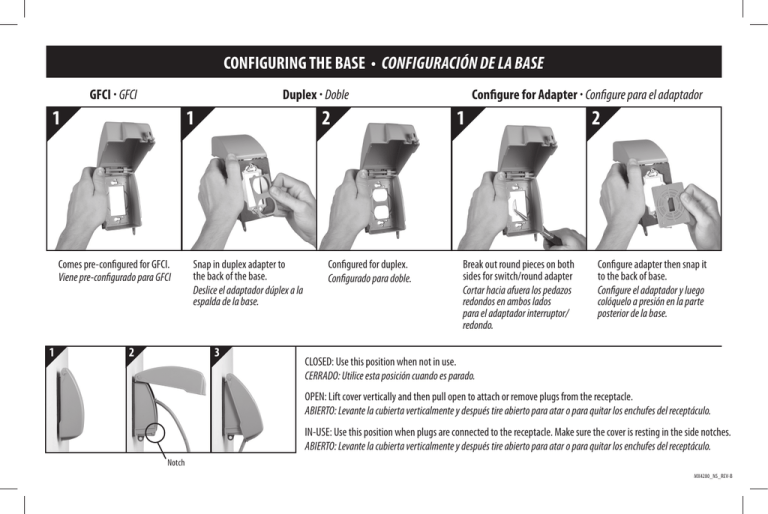
CONFIGURING THE BASE • CONFIGURACIÓN DE LA BASE GFCI · GFCI 1 1 Comes pre-configured for GFCI. Viene pre-configurado para GFCI 1 Configure for Adapter · Configure para el adaptador Duplex · Doble 2 2 Snap in duplex adapter to the back of the base. Deslice el adaptador dúplex a la espalda de la base. 3 Configured for duplex. Configurado para doble. 1 Break out round pieces on both sides for switch/round adapter Cortar hacia afuera los pedazos redondos en ambos lados para el adaptador interruptor/ redondo. 2 Configure adapter then snap it to the back of base. Configure el adaptador y luego colóquelo a presión en la parte posterior de la base. CLOSED: Use this position when not in use. CERRADO: Utilice esta posición cuando es parado. OPEN: Lift cover vertically and then pull open to attach or remove plugs from the receptacle. ABIERTO: Levante la cubierta verticalmente y después tire abierto para atar o para quitar los enchufes del receptáculo. IN-USE: Use this position when plugs are connected to the receptacle. Make sure the cover is resting in the side notches. ABIERTO: Levante la cubierta verticalmente y después tire abierto para atar o para quitar los enchufes del receptáculo. Notch MX4280_NS_REV-B MX4280 SERIES • MX4280 SERIE INSTALL UNIT • PARA INSTALAR LA UNIDAD IMPORTANT: Turn off power to receptacle at the circuit breaker box or equivalent. Configure base as shown on other side. Back-out box screws. (Note: Make sure that box is flush or slightly behind the finished surface and that receptacle is flush with the finished surface in accordance with NEC 406.4 and 314.20.) Using keyholes, place base with preattached gasket over screws. Tighten screws. Do not over-tighten mounting hardware. NOTE: Base should be installed on a smooth flat surface. To ensure a weatherproof seal on irregular surfaces such as brick or cedar siding, a 1/4 inch bead of non-hardening silicone caulk (not included) must be placed between the gasket and the mounting surface WARNING: Improper installation of any electrical device can cause serious injury or death. CAUTION: Device must protrude through the base or duplex/round adapters. If not, please use UL approved spacers (not included) to move the device forward in the box. DIAGRAM: GFCI Installation DIAGRAMA: Instalación de GFCI Screws Los Tornillos Keyholes Hoyo de Tornillos (Not Included) No Incluido Receptacle Box La Caja Receptáculo Gasket La Junta Base La Base IMPORTANT: Turn off power to outlet. IMPORTANTE: Desconecte corriente del circuito del desaque o toma. IMPORTANTE: Desconecte corriente del circuito del desaque o toma. Configure la base como se ilustra al lado. Coloque la empaquetadura sobre los tornillos. (Nota: Asegurece que la caja este a nivel con la pared o un poco mas abajo de la superficie terminada y el receptor este a nivel de la superficie terminada de acuerdo con el NEC 406.4 y 314.20.) Usando los ojos de la cerradura, ponga la base con la junta pre-atada sobre los tornillos. Apriete los tornillos. No apriete demasiado los accesorios de montaje. NOTA: La base deberá instalarse en una superficie suave y plana. A fin de garantizar un sello a prueba de agua en superficies irregulares, tales como ladrillo o tablas de cedro, se deberá colocar un reborde de 1/4 de pulgada de calafateo de silicón (no incluido) flexible entre el empaque y la superficie de montaje. AVISO: Instalacion incorrecta del algun aparato electrico puede causar heridas graves o hasta la muerte. Precaucion: El aparato debe salir de la base o duplex/adaptador redondo. Si no utilice expanciones aprovados por UL (no incluidos) para mover el aparato hacia el frente de la caja. MX4280_NS_REV-B
