Electrical connection Instalation of the spot track
Anuncio
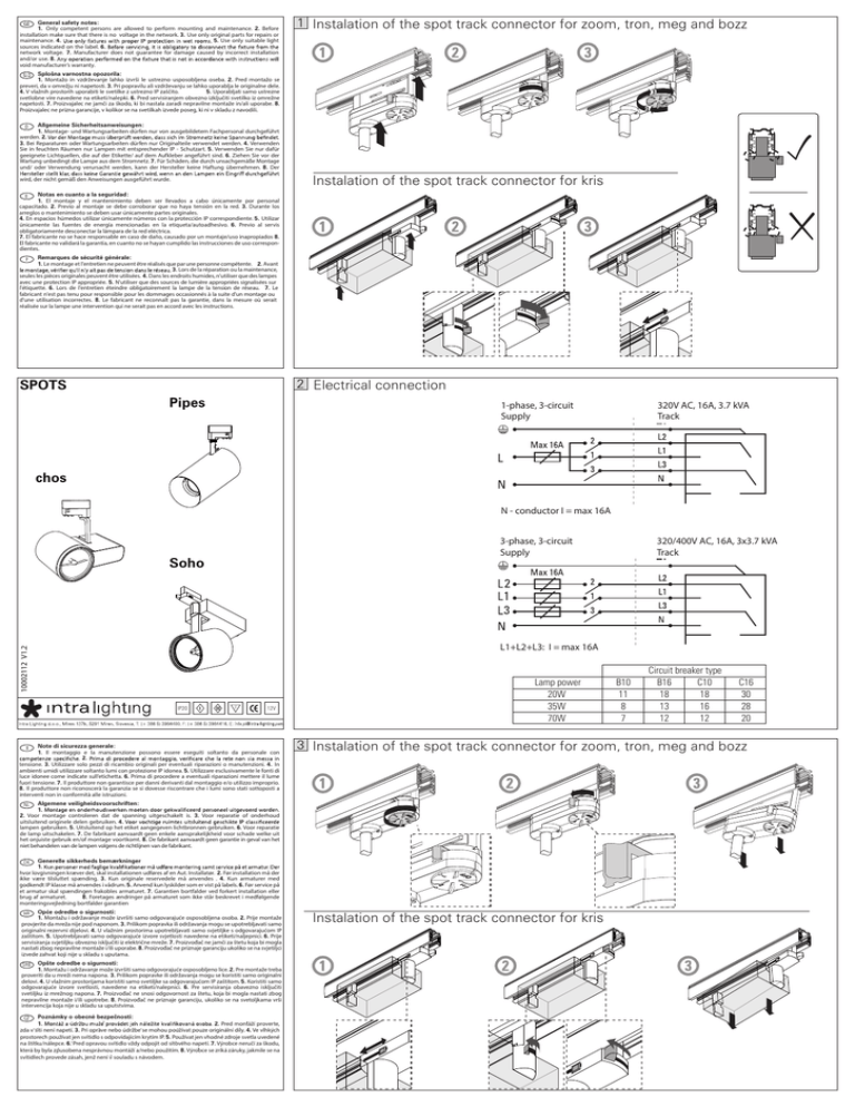
General safety notes: 1. Only competent persons are allowed to perform mounting and maintenance. 2. Before installation make sure that there is no voltage in the network. 3. Use only original parts for repairs or maintenance. 4. 5. Use only suitable light sources indicated on the label. 6. network voltage. 7. Manufacturer does not guarantee for damage caused by incorrect installation and/or use. 8. void manufacturer’s warranty. Instalation of the spot track connector for zoom, tron, meg and bozz Splošna varnostna opozorila: 1. Montažo in vzdrževanje lahko izvrši le ustrezno usposobljena oseba. 2. Pred montažo se preveri, da v omrežju ni napetosti. 3. Pri popravilu ali vzdrževanju se lahko uporablja le originalne dele. 4. V vlažnih prostorih uporabiti le svetilke z ustrezno IP zaščito. 5. Uporabljati samo ustrezne svetlobne vire navedene na etiketi/nalepki. 6. Pred servisiranjem obvezno izključiti svetilko iz omrežne napetosti. 7. Proizvajalec ne jamči za škodo, ki bi nastala zaradi nepravilne montaže in/ali uporabe. 8. Proizvajalec ne prizna garancije, v kolikor se na svetilkah izvede poseg, ki ni v skladu z navodili. Allgemeine Sicherheitsanweisungen: 1. Montage- und Wartungsarbeiten dürfen nur von ausgebildetem Fachpersonal durchgeführt werden. 2. 3. Bei Reparaturen oder Wartungsarbeiten dürfen nur Originalteile verwendet werden. 4. Verwenden Sie in feuchten Räumen nur Lampen mit entsprechender IP - Schutzart. 5. Verwenden Sie nur dafür geeignete Lichtquellen, die auf der Etikette/ auf dem Aufkleber angeführt sind. 6. Ziehen Sie vor der Wartung unbedingt die Lampe aus dem Stromnetz. 7. Für Schäden, die durch unsachgemäße Montage und/ oder Verwendung verursacht werden, kann der Hersteller keine Haftung übernehmen. 8. Der Instalation of the spot track connector for kris wird, der nicht gemäß den Anweisungen ausgeführt wurde. Notas en cuanto a la seguridad: 1. El montaje y el mantenimiento deben ser llevados a cabo únicamente por personal capacitado. 2. Previo al montaje se debe corroborar que no haya tensión en la red. 3. Durante los arreglos o mantenimiento se deben usar únicamente partes originales. 4. En espacios húmedos utilizar únicamente números con la protección IP correspondiente. 5. Utilizar únicamente las fuentes de energía mencionadas en la etiqueta/autoadhesivo. 6. Previo al servis obligatoriamente desconectar la lámpara de la red eléctrica. 7. El fabricante no se hace responsable en caso de daño, causado por un montaje/uso inapropiados 8. El fabricante no validará la garantía, en cuanto no se hayan cumplido las instrucciones de uso correspondientes. Remarques de sécurité générale: 1. Le montage et l'entretien ne peuvent être réalisés que par une personne compétente. 2. Avant 3. Lors de la réparation ou la maintenance, seules les pièces originales peuvent être utilisées. 4. Dans les endroits humides, n'utiliser que des lampes avec une protection IP appropriée. 5. N'utiliser que des sources de lumière appropriées signalisées sur l'étiquette. 6. Lors de l'entretien éteindre obligatoirement la lampe de la tension de réseau. 7. Le fabricant n'est pas tenu pour responsible pour les dommages occasionnés à la suite d'un montage ou d'une utilisation incorrectes. 8. Le fabricant ne reconnaît pas la garantie, dans la mesure où serait réalisée sur la lampe une intervention qui ne serait pas en accord avec les instructions. Electrical connection SPOTS Pipes 1-phase, 3-circuit Supply 320V AC, 16A, 3.7 kVA Track chos N - conductor I = max 16A 3-phase, 3-circuit Supply Soho 320/400V AC, 16A, 3x3.7 kVA Track 2 1 3 10002112 V1.2 L1+L2+L3: I = max 16A IP20 12V Note di sicurezza generale: 1. Il montaggio e la manutenzione possono essere eseguiti soltanto da personale con 2. tensione. 3. Utilizzare solo pezzi di ricambio originali per eventuali riparazioni o manutenzioni. 4. In ambienti umidi utilizzare soltanto lumi con protezione IP idonea. 5. Utilizzare esclusivamente le fonti di luce idonee come indicate sull’etichetta. 6. Prima di procedere a eventuali riparazioni mettere il lume fuori tensione. 7. Il produttore non garantisce per danni derivanti dal montaggio e/o utilizzo improprio. 8. Il produttore non riconoscerà la garanzia se si dovesse riscontrare che i lumi sono stati sottoposti a interventi non in conformità alle istruzioni. Lamp power 20W 35W 70W DK Generelle sikkerheds bemærkninger 1. hvor lovgivningen kræver det, skal installationen udføres af en Aut. Installatør. 2. Før installation må der ikke være tilsluttet spænding. 3. Kun originale reservedele må anvendes . 4. Kun armaturer med godkendt IP klasse må anvendes i vådrum. 5. Anvend kun lyskilder som er vist på labels. 6. Før service på et armatur skal spændingen frakobles armaturet. 7. Garantien bortfalder ved forkert installation eller brug af armaturet. 8. Foretages ændringer på armaturet som ikke står beskrevet i medfølgende monteringsvejledning bortfalder garantien SRB Opšte odredbe o sigurnosti: 1. Montažu i održavanje može izvršiti samo odgovorajuće osposobljeno lice. 2. Pre montaže treba proveriti da u mreži nema napona. 3. Prilikom popravke ili održavanja mogu se koristiti samo originalni delovi. 4. U vlažnim prostorijama koristiti samo svetiljke sa odgovarajućom IP zaštitom. 5. Koristiti samo odgovarajuće izvore svetlosti, navedene na etiketi/nalepnici. 6. Pre servisiranja obavezno isključiti svetiljku iz mrežnog napona. 7. Proizvođač ne snosi odgovornost za štetu, koja bi mogla nastati zbog nepravilne montaže i/ili upotrebe. 8. Proizvođač ne priznaje garanciju, ukoliko se na svetoljkama vrši intervencija koja nije u skladu sa uputstvima. Poznámky o obecné bezpečnosti: 1. 2. Pred montáží proverte, zda v síti není napetí. 3. Pri oprave nebo údržbe se mohou používat pouze originální díly. 4. Ve vlhkých prostorech používat jen svítidlo s odpovídajícím krytím IP. 5. Používat jen vhodné zdroje svetla uvedené na štítku/nálepce. 6. Pred opravou svítidlo vždy odpojit od sítového napetí. 7. Výrobce neručí za škodu, která by byla zpusobena nesprávnou montáží a/nebo použitím. 8. Výrobce se zríká záruky, jakmile se na svítidlech provede zásah, jenž není v souladu s návodem. Circuit breaker type B16 C10 18 18 13 16 12 12 C16 30 28 20 Instalation of the spot track connector for zoom, tron, meg and bozz Algemene veiligheidsvoorschriften: NL 1. 2. Voor montage controleren dat de spanning uitgeschakelt is. 3. Voor reparatie of onderhoud uitsluitend originele delen gebruiken. 4. lampen gebruiken. 5. Uitsluitend op het etiket aangegeven lichtbronnen gebruiken. 6. Voor reparatie de lamp uitschakelen. 7. De fabrikant aanvaardt geen enkele aansprakelijkheid voor schade welke uit het onjuiste gebruik en/of montage voortkomt. 8. De fabrikant aanvaardt geen garantie in geval van het niet behandelen van de lampen volgens de richtlijnen van de fabrikant. Opće odredbe o sigurnosti: 1. Montažu i održavanje može izvršiti samo odgovarajuće osposobljena osoba. 2. Prije montaže provjerite da mreža nije pod naponom. 3. Prilikom popravka ili održavanja mogu se upotrebljavati samo originalni rezervni dijelovi. 4. U vlažnim prostorima upotrebljavati samo svjetiljke s odgovarajućom IP zaštitom. 5. Upotrebljavati samo odgovarajuće izvore svjetlosti navedene na etiketi/naljepnici. 6. Prije servisiranja svjetiljku obvezno isključiti iz električne mreže. 7. Proizvođač ne jamči za štetu koja bi mogla nastati zbog nepravilne montaže i/ili uporabe. 8. Proizvođač ne priznaje garanciju ukoliko se na svjetiljci izvede zahvat koji nije u skladu s uputama. B10 11 8 7 Instalation of the spot track connector for kris Asennusohje D2252g FIKosketinkiskojärjestelmän asennusohje DMontageanweisung für Stromschienen 3-vaih. (3P+N+PE) Un 400V, In 16A 50Hz Suojausluokka I, IP 20 Asennuskorkeus suositus min. 1,7 m 3-Phasen (3P+N+PE) Un 400V, In 16A 50 Hz Schutzklasse I, IP 20 SMonteringsanvisning för kontaktskensystem GBInstallation instructions of lighting track system 3-fas. (3P+N+PE) Un 400V, In 16A 50Hz Skyddsklass I, IP 20 Min. Installationshöjd 2,2 m (S) 3-phase. (3P+N+PE) Un 400V, In 16A 50Hz Class I, IP 20 3-phases (3P+N+PE) Un 400V, In 16A 50 Hz Classe I, IP 20 Trifase (3P+N+PE) Un 400V, In 16A 50 Hz Classe di protezione I, IP 20 3-fases (3P+N+PE) Un 400V, In 16A 50Hz Clase I, IP 20 *) Peut être utilisé comme alimentation *) Anslutningsmöjlighet *) Ptede ser usado como toma de alimentación *) Può essere utilizzato per l’alimentazio *) Can be used as feed IIstruzioni per I’installazione dei binari elettrificati ESInstrucciones de instalación para carril de iluminación. *) Virransyöttömahdollisuus *) Einspeisung möglich FInstruction d’installation pour un système des rails d’allumage XTSF 40 10 0 66 XTS 14 *) XTS 11 * ) XTS 4100 (l=1000) XTS 4200 (l=2000) XTS 4300 (l=3000) XTS 4400 (l=4000) XTS 12 *) l 66 XTSF 10 XTSA 71 XTS 21 10 0 XTS 38 *) GA 70 l XTSF 4100 (l=1000) XTSF 4200 (l=2000) XTSF 4300 (l=3000) XTSF 4400 (l=4000) XTS 41 XTSF 30 XTS 37 *) VALAISINPISTOTULPPA ADAPTER XTSA67V-3 ja GB67V-3 GA 69 GA 30 XTS 35 *) XTS 36 *) GA 100 66 XTSA 67V 1:1 1:1 66 GA 300 GAT 69 XTS 40 *) XTS 39 *) XTSA 67 XTS 34 *) XTSA 67S XTSA 68 FISDGBFESI- N-johtimen sijaintia osoittava epäsymmetriaharja on merkitty paksulla viivalla Kanten som utmärker N-ledaren är märkt med en bred linje. Der Nulleiter ist mit einer breite Linie gezeichnet. The placing of the N-conductor is pointed out with a wide line. La position du conducteur N est indiquée par la ligne en gras. La posición del conductor Neutro viene indicado por la linea ancha. La posizione del conduttore N (neutro) viene indicata da una linea in grassetto. XTSF 30 o o 90 ,180 , 270o o o o 60 - 300 o 90 ,180 , o 270 XTS 24 l=160 o o 0 - 360 XTS 23 l=175 FI- Kiskon katkaisu S- Kapning av skenan D- Kürzen der Schiene XTSV 12 GB- Cutting of tracks on site F- Coupe des rails sur le lieu d’installation ES- Cortado de los carriles de iluminación sobre el terreno 1 I- Taglio del binario in loco FI- 1. Kiskon katkaisu 2. Taivutusavain painetaan paikoilleen 3. Taivutus 4. Johtimet taivutettu 5. Tulkkaus D- S- 1. 2. 3. 4. 5. GB- 1. Cutting of tracks Kapning Böjverktyget trycks på plats Böjning Ledarna är böjda Tolkning 1. Kürzen der Schiene 2. Der Biegewerkzeug wird im platz gedrückt 3. Biegung 4. Die Leitern sind gebogen 5. Prüfung 2. Placing the bending tool into the track 3. Bending 4. Conductors bent 5. Gauging 3 2 F- 5 4 1. Couper le rail 2. Poser la pince à plier dans le rail 3. Plier 4. Conducteurs pliés 5. Vérification des conducteurs pliés I- ES- 1. Cortado del carril 1. Taglio del binario 2. Posizionamento dell’ attrezzo perla piegatura dei conduttori nel binario’ 3. Piegatura dei conduttori 4. I conduttori sono piegati 5. Verifica dell’ esatto posizionamente dei conduttori 2. Posicionamiento de la herramienta de doblado en el carril 3. Doblado 4. Conductores doblados 5. Comprobación de los conductores doblados FI- Kytkentä GA 100 / XTSA 68 Asennuksessa noudatettava ko. maan asennusmääräyksiä. GA 69 230 V, 6 A GA 300 230 V, 3 A S- Koppling Vid monteringen bör vederbörande lands monteringsanvisningar följas. D- Anschluss Örtliche Vorschriften befolgen. GB- Connection Local installation requirements have to be followed. F- Connexion La réglementation locale doit être suivie lors de I’installation. ES- Conexionado La instalación particular ha de cumpir los requerimientos locales. I- Connessione È necessario osservare le normative nazionali per I’installazione. 2 3 1 FI- Virranottolaitteet: S- Strömuttagsdon: D- Adaptoren: GB- Adapters: F- Adaptateurs: ES- Adaptadores: I- Adattatori: FI- Liitososien asennus kiskoon D- Montageanweisung der Verbinder F- Installation des raccords I- Installazione dei giunti nel binario 1. Ohjausnokka 2. Ura 3. Lukitusruuvi 1. Steuerungsnase 2. Schlitz 3. Arretierschraube 1. Point de guidage 2. Sillon 3. Vis de verrouillage 1. Guida 2. Scanalatura 3. Vite di fissaggio S- Montering av kontaktdon i skenan GB- Installation of the connection parts into the track ES- Instalación de los conectores en el carril 1. Styrnäbb 2. Skåra 3. Fästskruv 2 Asennusohjeet GA 100 GA 69 Monteringsanvisningar XTSA 67 GAT 69 XTSA 67S GA 300 Montageanweisungen XTSA 68 Installation instructions Instruction d’installation Instrucciones de instalación Istruzioni per I’installazione 1. Guide lug 2. Groove 3. Lock screw 1. Lengueta guia 2. Canal 3. Tomillo de anclaje FRANCE SKB 18 us parties de suspension Kiinnitys ja D- Befestigung und F- Fixation des rails et I- Ancoraggio dei binari GB- Fastening of the capacité dey charge des e portata delle briglie gnikkeiden och tracks and Belastung loading der Klammern ES- Fijación del carril 11+XTS 41 rmitettavuus parties de suspension tning capacity of themontage clamps capacidad deXTS carga Instructions de Montagevoorrschrift Monteringsanvisning GB- Fastening of thede las fijaciones RCS750 EPSL Fastsättning och tracks and loading Fijación del carril y 66 ESAsennusohje D1365f D1365e SKB 21 enas belastning capacity of the clamps Istruzioni capacidaddi de carga XTS 14Fmax. Installation instructions montaggio 100 N 10Asennusohje de las fijaciones 0 RCS750 CPS SKB 16 Intruções de M 750 Track circuit Montageanweisung FI- Kiinnitys FI- ja Kiinnitys ja BP14-RN20-VIVIER Instructions 41600 LAMOTTE-BEUVRON XTS 21 FRANCE D- Befestigung D- Befestigung und und F- Fixation F-des Fixation rails et des rails etI- Installation in kiinnikkeiden kiinnikkeiden Belastung Belastung der Klammern der Klammern capacité de des charge de des charge e FI- Kiinnitys ja D- Befestigung D- Befestigung und F- Fixation desrails rails et FI- Kiinnitys ja und F- capacité Fixation et des Instrucciones de montaje Instrukcja montazu kuormitettavuus kuormitettavuus departies suspension de suspension kiinnikkeiden Belastung der Klammern parties capacité de charge des kosketinkiskojen kiinnitys SKB 18 Laipallisten kiinnikkeiden Belastung der Klammern capacité de charge des +neutral+earth) I- Kiinnitys ja D- Befestigung und F- Fixation des rails et I- Ancoraggio dei binari kuormitettavuus parties de suspension XTS 12+XTS Kiinnitys Belastung ja D- Befestigung und de chargeFFixation des rails etFastening I-ofAncoraggio dei41 binari Montageanw innikkeiden der Klammern capacité des e portata delle briglie GBthe Auormitettavuus / 400 Mounting V.FIInstructions de m of recessed tracks kiinnikkeiden Belastung der Klammern de charge des and loading e portata delle briglie BP14-RN20-VIVIER l capacité EPSR parties suspension S- de Fastsättning och XTS tracks ES- Fijación del carril y 11+XTS 41 RCS750 SKB 16 GB- Fastening GB- Fastening of the of the kuormitettavuus parties de suspension 55 Fmax. 200 N 18 D- Befestigung F-des Fixation des railsI- et I- Ancoraggio I- dei Ancoraggio dei dei D- Befestigung D- Befestigung undund SKB und F- Fixation F- Fixation des railsrails et et Ancoraggio binari S- binari Fastsättning S- binari Fastsättning och och tracks tracks loading and ES- Fijación ES-del Fijación carril del y carril y GB-and Fastening ofloading the Belastung der Klammern capacité dedes chargeedes e portata edelle portata briglie delle briglie Belastung Belastung der der Klammern Klammern capacité capacité de charge de charge des portata delle briglie fästenas belastning fästenas belastning capacity capacity theloading clamps of the clampscapacidad capacidad de carga de carga tracksof and SFastsättning och ES- Fijación del carril y SKB 21 de suspension parties parties de suspension departies suspension de las fijaciones de lasde fijaciones capacity of the clamps fästenas belastning capacidad carga XTSF 40 Fmax. 100 N GBof the GB-GBFastening ofFastening the Fastening of the de las fijaciones parties de suspension 41600 LAMOTTE-BEUVRON GBFastening ofESthe S- Fastsättning och tracks and loading ESFijación ESFijación carril yfästenas carril y belastning - Fastsättning S- Fastsättning ochoch kuormitettavuus tracks and loading Fijación del del carril y del tracks and loading capacity of the clamps capacidad de carga XTS 21 clamps GBFastening of the fästenasoch belastning capacity of the capacidad capacidad de carga de carga ästenas fästenas belastning belastning capacity of the clamps capacidad de carga capacity of the clamps - Fastsättning tracks and loading ESFijación del carril y deSKBlas FRANCE XTSF 21 fijaciones BP14-RN20-VIVIER de las fijaciones de las fijaciones de las fijaciones 6 SKB 18 SKB 18 XTSF 40 6 31,5 S- Fastsättning och tracks and loading ESFijación del carril y I- FIKiinnitys Kiinnitys FIja ja Kiinnitys ja iinnikkeiden kiinnikkeiden kiinnikkeiden uormitettavuus kuormitettavuus kuormitettavuus RCS750 EPSL RCS750 Track ästenas belastning capacity of the clamps capacidad de carga 41600 LAMOTTE-BEUVRON fästenas belastning capacity(3P+N+PE) of the clamps - 3-vaiheinen de las fijaciones capacidad de carga XTS 21 XTS 21 de las fijaciones - U 400 V, I 16 A 50 Hz SKB 16 FRANCE 3-circuit n L=1m Montagevoorrschrift SKB 16 SKB 21 RCS750 Fmax. 100 N L100 18 (3P+N+PE) - SKB 3-phase XTS 11 XTS 36 - Un 400 V, In 16 A1250 Hz 37 SKB 18 BP14-RN20-VIVIER BP14-RN20-VIVIER BP14-RN20-VIVIER 40 40 XTSF 40 Class I, IP20 14 38 XTSFXTSF 2 41600 41600 LAMOTTE-BEUVRON LAMOTTE-BEUVRON 41600 LAMOTTE-BEUVRON 34 39 BP14-RN20-VIVIER 56 RCS750 RCS750 XTS 21 XTS 21 RCS750 XTS 21 XTS 11 XTS 36 35 40 FRANCE FRANCEFRANCE XTKRF & GBF R SKB 18 BP14-RN20-VIVIER BP14-RN20-VIVIER BP14-RN20-VIVIER 41600 LAMOTTE-BEUVRON 41600 LAMOTTE-BEUVRON XTS 21 XTS 21 41600FRANCE LAMOTTE-BEUVRON SKB 21 FRANCE XTS 21 l FRANCE XTSF 40 Monteringsanvisning SKB 12/SKB10 XT XTS 12+ RCS750 E Monteringsanvisn l +L2+ Instructions de montageIstruzioni Montagevoorrschrift 55 1 Installation instructions di montaggio Asennusohje (L BP14-RN20-VIVIER L200 SKB 12/SKB10 12 37 L400 41600 LAMOTTE-BEUVRON 14 38 L300 Fmax. 200 N SKB 16 RCS SKB 16 SKB 16 3 41600 LAMOTTE-BEUVRON Instructions Instructions de montage de montage M XTS 21 Asennusohje montaggio XTS 11 XTS XTS 36 11 XTS Instructions de montage FRANCE montaje Instrukcja montazu XTSF 40 12 37 12 FRANCE 21 BP14-RN20-VIVIER 34 39 - 1-vaiheinen (P+N+PE) BP14-RN20-VIVIER XTSF 40 SKBdi Installation instructions Istruzioni Montageanweisung deFmax. 100 N 35 Instrucciones 40 - U 250 V, IBP14-RN20-VIVIER 16 A 50 Hz 41600 XTS 11 XTS 36 41600 LAMOTTE-BEUVRON XTS 21 LAMOTTE-BEUVRON XTSF4200 XTSF4300 14 12 38 14 l 37 Fmax. 200 -NSuojausluokka 41600 LAMOTTE-BEUVRON XTS 21I, IP20 34 14 39 34 BP14-RN20-VIVIE BP14-RN 38 Installation Installation instructions instructions Is SKB 12/SKB10 SKB 12/SKB10 SKB 12/SKB10 FRANCE RCS750 ICP FRANCE -de Asennuskorkeus suositus 1,7 mMontagevoorrschrift Instructions Instructions Instructions de montage montage de montage Montagevoorrschrift Monteringsanvisning Monteringsanvisning Monteringsanvisning 36 35 34Intruçõ 35 40 Intru XTS 21Montagevoorrschrift SKB 21 SKB 21 SKB 21 39 BP14-RN20-V 1 41600 2 L=1m L=2m L=3m L=4m Installation instructions LAMOTTE 41600 L3 FRANCE XTS 11 XTS XTS 11 36 XTS XTS 36 11 XTS 36 Montageanweisung Instrucciones de montaje Instrukcja monta Fmax.Fmax. 100 N100 N Fmax. 100 N SKB 16 35 40 55 olevaan 55 uraan RCS750 RCS750 - 1-phase (P+N+PE) Fmax. 200 N Fmax. 200 N Kiinnitys katossa 12 12 37 37 12 37 41600 LAMOT FRANCE FRANCE SKB 21 55 Fmax. 200 N 14 14 38 38 14 38 Rec L200Installation Rec L300 Mounting indi a groove in the ceiling Montageanweisung Montageanweisung FRANCE In XTS 11+XTS 41 34Istruzioni 39 39 39 - Uinstructions 250 I 16 A34BP14-RN20-VIVIER 5034 Hz BP14-RN20-VIVIER BP14-RN20-VIVIER XTS4100 XTS4300 XTS4400 Installation Installation instructions instructions Istruzioni Istruzioni didi montaggio montaggio montaggio Asennusohje Asennusohje Asennusohje Instructions de montage M SKBV,XTS4200 16 35 35 40 40 35 40 Montageanweisung XTSP 11 Montagevoorrschrift l Class I, IP20 41600 41600 LAMOTTE-BEUVRON LAMOTTE-BEUVRON 41600 LAMOTTE-BEUVRON SKB 16 23 31.5 RCS750 EPSL 55 55 55 Instructions de montage Fmax. Fmax. 200 N 200 N Fmax. 200 N SKB 10T SKB 21 55 RCS750 CS XTSF & GBF SKB 21 FRANCE FRANCEFRANCE 6SKB XTS 36 RCS750 RCS750 RCS750 RCS750 Fmax. 100 Nde 11+XTS 4111 6Instrukcja Montageanweisung Montageanweisung Montageanweisung Instrucciones Instrucciones Instrucciones de montaje montaje de montaje Instrukcja Instrukcja montazu montazuXTS 21 SKB 21 montazu Instructions de montage Montagevoorrschrift 2 SKB 12/SKB10 12 37 A B l=3000 Installation instructions Istruzioni diXTS montaggio Katso myös ko. kiskojärjestelmien erilliset XTS 41 Instructions de montage Montagevoorrschrift Monter - kiskoSKB voidaan kiinnittää laipoista (A) tai pohjan läpi (B) 21 1 SKB 21 Instructi Ins L100 L200 L300 L400 56 SKB 12/SKB10 EPSL 14 38 0 RCS750 Instructions Montagevoorrschrift XTS 11 de XTS 36montage - Tapa A: ruuvi Ø 3,0-4,5, kiinnitysväli 500 mm 34Instruc SKB 21 5asennusohjeet. Fmax. 100 N 5 45611.2 39 BP14-RN20 31. 55 instructions 55 Installation 6 12 37 XTS 11 XTS 36 Ø Tapa B: XTSF ruuvi uppokantainen 3,0, GBF ruuvi 6 EP55 RCS750 35 Trac 40 SP 4R XTS 36 *) SKB 21SKB 21Fmax.SKB10021 N RCS750 See also XTSF4200 separate inst.instructions of each 14 38 RCS750 12 37 Installation instructions Istruzioni dimontaje montaggio Ø 3,0, kupukantainen 1000 mm 41600 XTSF4300 LAM Installati InsT l 11+XTS XTS 11+XTS XTS 11+XTS 41 41 kiinnitysväli 41RCS750 Montageanweisung Instrucciones de I Tra Instructions Instructions Instructions de34de montage Montagevoorrschrift Monteringsan Monteringsa Monte 39de montage 14Montagevoorrschrift 38XTS system. 3 55montage BP14-RN20-VIVIER Fmax. 200 N20 kg/m SKB 10T Installation instructions Istruzioni di montaggio Asennu - Montagevoorrschrift kuormitettavuus RCS750 TCP R Installa FRANCE 35instructions 34 39RCS750 RCS750 RCS750 EPSL EPSL EPSL A 40 BP14-RN20-VIVIER Installation Istruzioni di montaggio 55 255 553 1 41600 LAMOTTE-BEUVRON 35 6 640 66 can be fixed through the flanges (A) or through RCS750Track RCS750 - tracks 6Istruzioni 6 Montageanweisung RCS750 RCS750 Track Track Fmax. 200 N RCS750 Montage Mo GBF 55 41600 LAMOTTE-BEUVRON XTS XTS 1 Montageanweisung Instrucciones montaj Installation Installation Installation instructions instructions instructions Istruzioni Istruzioni didi montaggio montaggio di montaggio Asennusohje Asennusohj Asenn Asennuksessa otettava huomioon 1+L 1de 10Monta the track bottom (B) 55 Fmax. 200L300 N FRANCE (L +L (L +L +neutral+ +neu Rec L200 Rec 0 0 30 1 1 2 2 3 3 31.5 0 0 0 RCS7 RCS FRANCE Ø manner A: with screws 3,0-4,5, at distance of 500 mm l To be2observed3 Montageanweisung Instrucciones de montaje Instruk (L +L +L +neutra N XTSP 11 1 SP 4R 3 56 Ø 3,0 - manner B: XTSF with1flat head2 screws GBF Montageanweisung Instrucciones de montaje 16A 16A / mm, 400 / XTS 40 V.mV Montageanweisung Montageanweisung Montageanweisung Instrucciones Instrucciones Instrucciones dede montaje montaje Instrukcja Instrukcja Instruk mo RCS750 CS Øde with pan head screws 3,0,montaje both 16A at distance of 400 1000 mm - kiskojärjestelmien etusulake maks. 16 A. RCS / SKB 21 (L(L +L +L (L +L +L +neutral+earth) +L +neutral+earth) +neutral+earth) 8 noudatettava - max. load 20 kg/m 1 1 2 -12asennuksessa 3 23 3 0 l l=3000 6XTS 90°,180°, 41 20 asianomaisen maan asennusmääräyksiä 6Instru 100 SKB 21 16A 16A / 16A / 400 400 / V. 400 V. V. 45611.2 XTKRF 270° 500 l l l XTS 56 SKB 21 XTS 11+XT fuse 16 A 5 XTS 11+XTS 11+XTS XTS 11+X 4141 Instructions de montage560°300°Montagevoorr XTS-- Local 36max. *) XTS 35 *)50 RCS750 6 installation requirements have to*) Instructions montage Mo XTS 38 - kiskot voidaan de kiinnittää vain laipoista, katso XTSF: tapa AEP RCS750 RCS750 RCS750 EPSL EPSL RCS750 EP RCS750 RSKB 10 be followed RCS750 CCPE N Insta 500SKB 12 5TCP -L=4m kuormitettavuus 20 kg/m 6 6 5 SKB 10 SKB 10 6 L=1m L=2m L=3m RCS750 XCP 6 66 6 RCS750 RCS750 Track Track Track SKB 10T 55 RCS750 L=1m L SKB 10 SKB 10T SKB 10T SKB 16 32.5 n n n n (L +L +L 16 32.5 SKB 16 SKB 16 XTKRF 55 SKB 21 Fmax. 100 N 21 Fmax. 100 N SKB 32.5 RCS750 Track 3-circuit RCS750 Track (L +L +L +neutral+earth) 3-circuit 3-circu 3-circuit 3-circuit 16A / 3-circuit 400 V. (L +L +L +neutral+earth) 3-circuit 3-circuit 16A / 400 V. RCS750 Track 3-circuit RCS750 Track RCS750 Tr 6 RCS750 Track (L1+L2+L (L 3-circuit L=1m 3+neutral+earth) Installation instructions Istruzioni di(L m 3-circu 16+ 621(+ RCS750 Track XTS XTS 2121 XTS 3-circuit 3-circuit 3-circuit Installation instructions Istr 56 XTS4100 XTS4200 XTS4300 XTS4400 XTS4100 XT XTS 35 *) l=175 L=1m L=2m L=3m L=4m RCS750 RCS75 ICP ICP N L=2m Mont 16A / 400 V.L=4m XTS41 Kiinnitys katossa olevaan uraan Kiinnitys alaslasketun katon yhteydessä, 31.5 31.5RCS750 3-circuit 90°,180°, L=1m L=1m L=1m L=2m L=2m L=3m L=3m L=4m L=4m (L +neutral+earth) 31.5 RCS750 C 1+L 2+L 3L=3m (L +L +L N (L (L (L +neutral+earth) +L +neutral+earth) +neutral+earth) 3-circuit 31.5 3+neutr 1+L 1+L 2+L 12+L 3 2 3 3 1 2 Mounting in a groove in the ceiling laippoja käytetään kattolevyn tukemiseen RCS750 R 270° Montageanweisung Instrucciones 0°360° RCS750 RCS750 RCS750 RCS750 XTS4100 XTS4200 XTS4300 XTS4400 8 0 RCS75 XTS4100 XTS4100 XTS4100 XTS4200 XTS4200 XTS4200 XTS4300 XTS4300 XTS4300 XTS4400 XTS4400 XTS4400 Montageanweisung Ins 90°,180°, L100 66 16A / 400 V. (L +L +L +neutral+earth) 6 16A 16A / 16A / 400 400 / V. 400 V. V. Mounting in suspended ceilings 6 L100 L200 +neutral+earth) L300 L400 131.5 3+L +L 1002 (L 31.5 31.5 31.5 L100 16A / 400 SKB 10 SKB 10 SKB 10 SKB 12 SKB 12 SKB 10T 32.5 - the tracks can only be SKB 10Tfixed through the flanges, see above (A) - max. load 20kg/m SKB 12 SKB 10 32.5 32.5 SKB 10T SKB 10T SKB 10T Kiinnitys katossa olevaan uraan Mounting in a groove in the ceiling 32.5 32.5 32.5 32.5 32.5 32.5 32.5 66 I, IP20 - Asennuskorkeus suositus 1,7 m 32.5 55 32,5 L=2m SKB 12 L=3m XTS 14 Fmax. 200 N 06 Montageanweisu RCS750 CPS 55 6 10 55 RCS750 ICP SKB 18 - Suojausluokka SKB 18 SKB 18 L=4m (L1+L2+L 3+neutral+earth) Instructions de montage XTS4100 XTS4200 XTS4300 XTS4400 16A / 400 V. SKB 10 SKB 21 max. 100 N n Installation instru SKB 18 SKB 12 SP 4R SP 4R SP 4R Kiinnitys alaslasketun katon yhteydessä, laippoja käytetään kattolevyjen tukemiseen Mounting in suspended ceilings 32.5 32.5 32.5 32.5 32.5 32.5 2 1 3 32.5 32.5 32.5 / Instruction manual copyright, 05-1997, by Nordic Aluminium Ltd. / Piir. no D1365e / STAROFFSET OY 2 1 3 32.5 32.5 32.5 32.5 32.5 2 1 3 32.5 RCS750RCS750 Track Track 3-circuit 3-circuit(L (L +L +L (L +neutral+earth) +L +L +neutral+ 16A / 400 V. / 400 V. 16A 32.5 32.5 32.5 32.5 32.5 32.5 32.5 32.5 32.5 32.5 32.5 32.5 32.5 32.5 32.5 32.5 16A / 400 V./ 400 V. 16A SP 4R XTS 39B *) RCS750 TCP L 32.5 32.5 XTS 35 *) 270° XTSF & GBF 1 RCS750 2 3RCS750 XTSF RCS750 RCS750 RCS750 RCS750 RCS750 RCS750 RCS750RCS750 RCS750 RCS750 RCS750 RCS750 N RCS750 RCS750 60 XTSF, XTKRF & GBF RCS750 CCPE XTSF N L100 L100 L100 L200 L200 L200 L300 L300 L300 L400 L400 L400 SKB 31 XTS 38 *) - kisko voidaan kiinnittää laipoistalaipioista (A) tai pohjan läpi (B) -kisko voidaan kiinnittää (A) XTSF4200 XTSF4300 L300XTS 24L400 L100 L200 l XTS 23 - Tapa A: ruuvi Ø 3,0-4,5, kiinnitysväliN 500 mm - kiinnikkeellä 12 (XTSF, XTKRF)12 tai (XTSF) GBS 33(GBF) RCS750 XCP SKB RCS750 ACP -kiinnikkeillä SKB 10,ollaSKB tai pohjan läpi (B) - Tapa B: XTSF ruuvi uppokantainen Ø 3,0, GBFRCS750 ruuvi FCP helposti purettavissa, levyjä 6 XTSF4200 XTSF4200 XTSF4200 XTSF4300 XTSF4300 XTSF4300 L=1m- kattolevyrakenteen L=2m tulee L=3m L=4m l l l kupukantainen Ø 3,0, kiinnitysväli 1000 mm ei kiinnitetä kiskon laippoihin RCS750 RCS750 XTSF4200 XTSF4300 -kattolevyrakenteen tuee olla helposti l SKB 10 12/ 12 -Tapa A: ruuvi20Økg/m 3,0 – 4,5, kiinnitysväli SKB - kuormitettavuus 56 56L=4m L=1m L=1m L=1m L=2m L=2m L=2m L=3m L=3m1000 L=3m L=4m L=4m - ripustusväli enintään mm l=175 Rec L200 Rec L300 RCS750 RCS750 RCS750 RCS750 RCS750 RCS750 56 N1,2 kg/m connectionA possible 90°,180°, - kattolevyn kuormitus laippaa kohden purettavissa, levyjä ei kiinnitetä kiskon XTS4100 XTS4200 XTS4300 XTS4400 L=1m L=2m L=3m L= T-välilista 500mm - tracks can be fixed through the flanges (A) or through Rec Rec L200 L200 RecRec L200 Rec L300 L300 Rec - kiskosta ripustettava muu massa enintään 10 kg/SKB 10 T-bar L300 RCS750 RCS750 56 XTS4100 XTS4100 XTS4100 XTS4200 XTS4200 XTS4200 XTS4300 XTS4300 XTS4300 XTS4400 XTS4400 XTS4400 31.5 6XTSP 270° the track bottom (B) laippoihin XTSP XTSP 11 11 6 0°360° ripustusväli L= -Tapa B: 56 ruuvi Ø 3,0, 56 uppokantainen 56 SKB 10T 31.5 31.5 N - manner A: with screws Ø 3,0-4,5, at distance of 500 mm 31.5Rec L200 RCS750 Rec L300 RCS750 RCS750 RCS750 RCS750 RCS7 CSCS XTS4100 XTS4200 XTS4300 -ripustusväli enintään 1000mm - manner B: XTSF with flat head screws Ø 3,0 mm, GBFSKB 10 XTSXTS 36 X RCS750 RCS750 RCS750 RCS750 RCS750 RCS750 RCS750 RCS750 RCS750 SKB 12and XTS 35 XTS *)RCS750 35 12, *)RCS750 XTSF XTKRF withRCS750 clamp SKB GBF with clamp kiinnitysväli 1000mm SKB 10 L=2m L=3m L=4m 1,2 L=1m kg/m SKB 10T56 31.5 L100 L200 L300 L400 l=3000 l=3000 l=300 Ø 3,0, both at distance of 1000 mm with pan head screws XTSR XTS 35 *) SKB 12 GBS 33 L200 (and all with eg.L300 threaded rod SKB 31) RCS75 N L100 L100 L=1m L100 L200 L200 L300 L300 L400 L400 L400 RCS750 RCS750 CCPE CCPE XTS4 XTSV 12 L=2m L=3m L=4 -kattolevyn kuormitus laippaa kohden SKB 10T max. load 20 kg/m the ceiling plate structure must be easy to demount, the -kuormitettavuus 20 kg/m 1 2 3RCS750 RCS750 CCPERCS750 XTS 34 *) RCS750 RC XTS 24RCS RCS700 TDB XTS 39 *) and 2 the tracks31.5 are fixed onto each others. 1plates 3notXTS4400 1,2 kg/m XTS 23 XTS 36SP 36 *) XTS *) XTS 36 *) 36 *) enintään 1,2 kg/m XTS 35 35 *) XTS *) 35TCP *) L XTS 35 *) XTS4100 XTS4200 XTS4300 XTSF4200 XTSF4200 XTSF4200 XTSF4300 XTSF4300 RCS750 CCPI XTSXTS RCS750 RCS750 AC XTSF4200 XTSF4300 4R L100 L200 L300 XTKRF - hanging at XTSF4300 max. 1000 mm distance 500 XTS4200 XTS4300 RCS750 RCS750 RCS750 TCP TCP R RTCP RCSL RCS750 RCS750 RCS750 RCS750 CCPE CCPE CCPE NXTS4 - plate loadFCP max. 1,2 kg/m permuu track flange RCS750 TCP R R 3 3 3 3XTS4100 RCS750 CCPE 31.5 -kiskosta ripustettava massa -tracks can be fixed through the - other from track - kiskot voidaan kiinnittää vain laipoista, katso XTSF:31.5 tapa A N hanging N load max. 10 kg/hanging SP 4R RCS750 RCS750 RCS750 RCS750 RCS750 RCS750 XTS 36RCS750 *) XTS 3520*) 500 distance - kuormitettavuus kg/m RCS750 RCS750 RCS750 RCS750 RCS750 XTSF4200 XTSF4300 L1 enintään 10 kgNL300 / Rec ripustusväli flanges (A) or through the track bot*230-240 SP V24R cable connection possible Rec Rec L200 L200 Rec Rec L200 Rec L300 L300 5 3 4 3 RCS750 RCS750 RCS750 6 6 6 RCS750 TCP R RCS750 CCPE 6 RCS7 6 N N N L200 Rec L400 L300 L100 L200 tekninenRec L300 - the tracks can only be fixed through the flanges,56 see 56 56 66 66 XTS N6 6 34 *) tom Valmistaja, neuvonta ja myynti / Manufacturer 6 N N N (B)(A)N L100 L200 L300 L40 above RCS750 RCS750 56 RCS750 CC XTS 3 -with clamps SKB 10, SKB 12 - max. load A: 20kg/m N -Manner Ø 3,0 – 4,5, 90°,180°, 90°,180°, 90°,180° XTS 66with 66 screws 6 Rec L200 Rec L300 RCS7 66666 66 XTSF4200 XTSF4300 101000 100 -the ceiling plate structure must be N XTS 34 *) P.O.117, Box 117, FI-02401 Kirkkonummi, Finland 270° 270° 270° RC XTSV 12 at distance of 500mm P.O.Box FIN-02401 Kirkkonummi, Finland XTSF4200 XTSF4300 9 6 laippoja 56 XTS Kiinnitys alaslasketun katon yhteydessä, kattolevyjen tukemiseen 6 Tel. +358 20 7660 200, fax +358 20 7660 485 6käytetään XTS 3636 *) XTS *)Tel.easy 36 *)9towww.nordicaluminium.fi +358 68 251, fax +358 9 298 2154 RCS750 XTS XTS 3535 *) XTS *)135 *) N 6 *230-240 VL CCPI RCS700 TDB 0 demount, the plates and the Mounting in suspended ceilings L=1m L=2m XTS XTS 38 38 *) XTS *) 38 *) 0 -Manner B: with flat head screws RCS750 RCS750 TCP TCP R RTCP R RCS750 RCS750 RCS750 CCPE CCPE CCPE RCS750 RCS750 RCS750 L=1m 2 RCS750 RCS750 RCS750 XCP XCP XCP others XTS 36 *) are tracks not fixed onto each 6 distance61000mm RCS750 RCS750 6XTS 35 *) N N 1 N Rec 56 ØXTSF, 3,0,XTKRF supporting N & GBF6 XTS 38 XTS4200 *) L200 Rec SKB 31 N XT XTS4100 RCS750 TCP RL300 RCS750 230/400 V 16 A, 3×3.7 kW 230/400 V Rec A, 11.1 kW Rec 230 V 16 CCPE A, 3.7 kW 00 *230-240 V cable -hanging at16 max. 1000mm distance L200 L300 N N -max. load 20 kg/m N RCS750 XCP XTS4100 l=175 l=175 l=175 56 tai GBS 33(GBF) - kiinnikkeellä SKB 12 (XTSF, N NN N 31.5 5 3 4 1 2 XTKRF) XTS 36 *) XTS 35 *) 90°,180°, 90°,180°, 90°,180 - kattolevyrakenteen tulee olla helposti 56 max. 1,2 kg/m perXTS track38 *) L L-plate load N purettavissa, N N 12levyjä 31.5 RCS750 TCP R 0°- 360° ei kiinnitetä kiskon laippoihin1-circuit L L L RCS750 CCPE 3-phase RCS750 RCS750 270° 270° 270° R 0°0°360° 360° 3 SKB 12 3-circuit L N XTS 34 XTS *) 34 *) XTS 39 X RCS750 XCP flange L N N enintään N 1000 mm - ripustusväli l=175 RCS750 6 6 N max. 16 A max. 16 A XTS 666666 66 34 *) XTSR9 3 L100 L200 1 1 1 Nkg/mmax.6166A N N kattolevyn kuormitus laippaa kohden 1,2 0-other 00 from 0 RCS750 RCS750 CCPI CCPI RCS750 T-välilista XTS 0 0 XTStrack 35 *) CCPI hanging load max. N 10 kg/ L100RCS7 - kiskosta ripustettava muu massa enintään RCS750 NN N ripustusväli RC l=175 CCPE0°- 360° XTS 3434 *) XTS *) 34 *)35 *) XTS XTS 3939 *) XTS *) 39 *) XTS 36 *) XTS 38 38 *) X2 NXTS 10 kg /RCS750 hanging distance XTS NXTS 6 XTS XTS 23 23 XTS 23 XTSF4200 XT 6 6 1 *230-240 *230-240 V cable V connection cable connectio poss N N N RCS750 RCS750 RCS750 CCPI CCPI CCPI RCS750 RCS750 RCS750 TCP TCP L L TCP L RCS750 RCS750 RX XTS 36 *) 6 35 - XTSF and XTKRF with clamp SKB 12,XTS GBF with clamp 100 RCS750 N*) RCS750 3 1,2 kg/m TCP R RCS750 RCS750 FCP *230-240 VFCP cableFCP connection po CCPE GBS 33 (andRCS750 all with eg. threaded rod SKB 31) 1 3 0°360° RCS750 RCS750 CCPE 6 N TCP R - the ceiling plate be easy to demount, the N structure must N l=17 Veach 16 others. A,*) 3×3.7 kW 230/4001V l=175 16 A, RCS750 R 6 plates are not230/400 fixedconnection onto XTS*230-240 34 *)and XTS 39 66230 V 16 A, 3.7 kW 10 1,2 kg/m *230-240 *230-240 Vthecable Vtracks cable connection V connection cable possible possible possible 0 - hanging at max. 1000 mm distance XTS 23 Rec L200 Re 2 N RCS750 CCPI RCS750 TCP L N N N 3-phase - plate load max. 1,2 kg/m perL track flange L 0°-0° 3 1 XTS 34 RCS750 FCP N NXTSN39 *) L max. 10 kg/hanging L L - other from track hanging load 3-circuit 1-circuit56 XTS 34 *) 3 XTS N L L RCS75 distance N 56 16 A RCS750 TCP L max. 16 A max. 1623 A 66N NN 6 N 6 XTS NN RCS750 CCPI N max. RCS N possible XTSV XTSV 12 12XTSV 12 1 *230-240 V cable connection RCS750 F XTS XTS 3434 *) XTS *) 34 *) XTS XTS 3939 *) XTS *) 39 *) SP 4R SPSP 4R4R 2 1 3 FI- Kiskon kiinnitysväli ja kuormitettavuus Suositeltava kiinnitysväli I~1000 mm. Kiskoissa reiät kiinnitystä varten. D- Befestigungsabstand und Belastbarkeit Empfohlener Abstand I~1000 mm. Schlenen mit Befestigungslöcher. S- Skenans fästavstånd och belastning Rekommenderat fästavstånd I~1000 mm. Skenorna har fastsättningshål. GB-Fastening distance and loading capacity Rekommended fastening distance I~1000 mm. The tracks have fastening holes. F- Distance de fixation et Icapacité de charge Distance de fixation recommendée 1~1000 mm. Les rails ont des trous pour la fixation. ES- Distancia de fijación y capacidad de carga Distancia de fijación recomendada I~1000 mm. Tomillos incluidos, asi como taladros de fijación. Distanza di ancoraggio e portata La distanza di ancoraggio raccomandata è I~1000 mm. I binari sono dotati di fori di ancoraggio. FI- Järjestelmän osat ja käyttöturvallisuus D- Systembauteile und Sicherheit F- Système des rails et sécurité d’emploi I- Componenti del sistema e sicurezza d’uso Järjestelmässä saa käyttää vain tässä asennusohjeessa esitettyjä osia tämän ohjeen mukaisesti asennettuina. Järjestelmän valmistaja NORDIC ALUMINIUM Oyj ei vastaa järjestelmän turvallisuudesta ja toimivuudesta, jos jokin osa korvataan vieraalla osalla tai asennusohjeesta poiketaan. Vastuu siirtyy käyttäjälle, jonka on varmistuttava järjestelmän ja siihen kiinnitettyjen valaisimien/ kojeiden sähköisestä, mekaanisesta ja termisestä yhteensopivuudesta. Mit diesem Systemt dürfen nur in der Anweisung präsentierten und gemäß ihr installierten Teile eingebaut werden. Der Hersteller des Systems, NORDIC ALUMINIUM Plc, verantwortet nicht für die Sicherheit und die Funktion des Systems, falls irgendeiner Teil ausgetauscht wird oder die Montage-anweisung nicht befolgt wurde. In solchem Fall ist der Benutzer selbst dafür verantwortlich, sich der elektrische, mechanische und termische Anpassung des Stromschienensystems und der daran installierten Armaturen zu vergewissern. Il est obligatoire d’utiliser les composants présentés dans la notice d’installation et de suivre strictement les instructions lors de l’installation. NORDIC ALUMINIUM Plc, constructeur de ce système, n’est pas responsable de la sécurité et du fonctionnement du système d’allumage si d’autres composants que ceux de NORDIC ALUMINIUM sont utilisés ou si les instructions d’installation ne sont pas suivies. C’est la responsabilité de l’utilisateur de s’assurer de la compatibilité électrique,mécanique et thermique entre le système et les luminaires ou appareils qui y sont attachés. È permesso di utilizzare solo i componenti illustrati, che devono essere installati secondo queste istruzioni. NORDIC ALUMINIUM Plc, nella sua veste di fabbricante, non è responsabile per la sicurezza ed il funzionamento del sistema se i componenti utilizzati non fanno parte della specifica del prodotto né se non sono state eseguite alla lettera le istruzioni di installazione. Sarà responsabilità dell’ utente assicurarsi della compatibilità elettrica, meccanica e termica del sistema rispetto alle strutture sulle quali viene ancorato. S- Systemets delar och användningssäkerhet I systemet får användas endast delar som visas i och är monterade enligt denna anvisning. Systemets tillverkare NORDIC ALUMINIUM Plc ansvarar inte för systemets säkerhet och funktion om någon del ersätts med en främmande del eller om man avviker från monterings-anvisningen. Ansvaret överförs till användaren som bör förvissa sig om sken-systemets och där fastsatta armaturers elektriska, mekaniska och termiska anpassning till varandra. GB- Track system and operational safety It is allowed only to use the parts presented and they must be installed according to these installation instructions. NORDIC ALUMINIUM Plc as manufacturer of the system is not responsible for the safety and function of the system if parts not belonging to this are used or if any deviations from the installation instructions are made. It is then the user’s responsibility to ensure the electrical, mechanical and thermal compatibility between the system and the fixtures attached to it. ES- Elementos del sistema de carril y seguridad de uso Está permitido usar solamente los componentes presentados en estas instrucciones de instalación, asi como montados según se expone. NORDIC ALUMINIUM Plc, como fabricante del sistema de carril, no es responsable de seguridad y funcionamiento del mismo su Ud. Usa piezas no pertenecientes a nuestro sistema o si se aparta de las instrucciones de instalación. Es por tanto responsabilidad del usario asegurar la compatibilidad eléctrica, mecánica y térmica entre el sistema de carril y las luminarias en él instaladas. Valmistaja, tekninen neuvonta ja myynti Tillverkare Hersteller Constructeur Manufacture Fabbricazione P.O. Box 117, FI-02401 Kirkkonummi, Finland Tel. +358 20 7660 200, fax +358 20 7660 485 www.nordicaluminium.fi 4
