DATA A - 5238 ED 04 (Page 1)
Anuncio
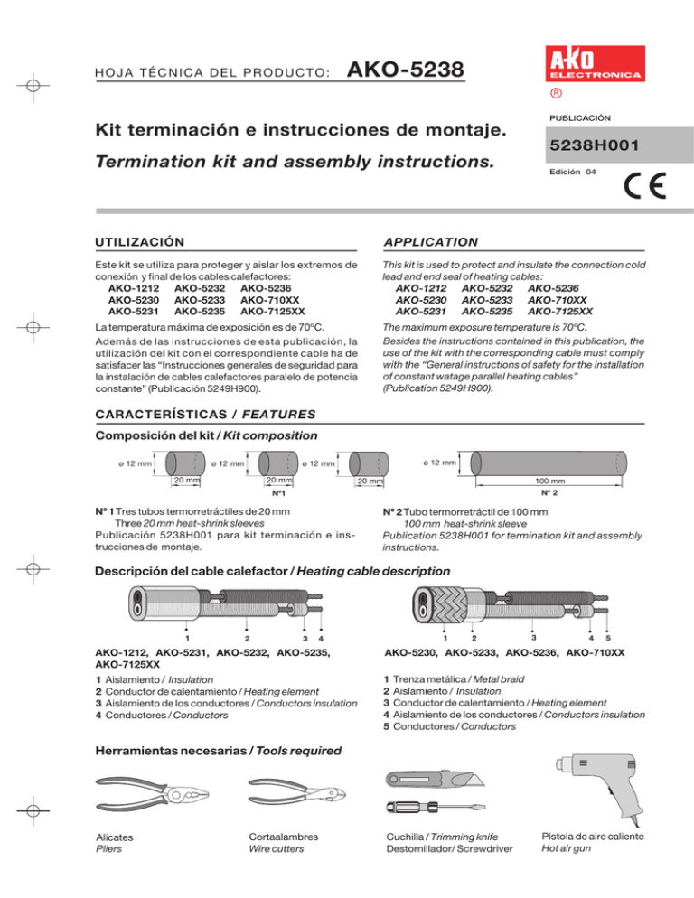
HOJA TÉCNICA DEL PRODUCTO: AKO-5238 R PUBLICACIÓN Kit terminación e instrucciones de montaje. 5238H001 Termination kit and assembly instructions. Edición 04 UTILIZACIÓN APPLICATION Este kit se utiliza para proteger y aislar los extremos de conexión y final de los cables calefactores: AKO-1212 AKO-5232 AKO-5236 AKO-5230 AKO-5233 AKO-710XX AKO-5231 AKO-5235 AKO-7125XX This kit is used to protect and insulate the connection cold lead and end seal of heating cables: AKO-1212 AKO-5232 AKO-5236 AKO-5230 AKO-5233 AKO-710XX AKO-5231 AKO-5235 AKO-7125XX La temperatura máxima de exposición es de 70ºC. The maximum exposure temperature is 70ºC. Besides the instructions contained in this publication, the use of the kit with the corresponding cable must comply with the “General instructions of safety for the installation of constant watage parallel heating cables” (Publication 5249H900). Además de las instrucciones de esta publicación, la utilización del kit con el correspondiente cable ha de satisfacer las “Instrucciones generales de seguridad para la instalación de cables calefactores paralelo de potencia constante” (Publicación 5249H900). CARACTERÍSTICAS / FEATURES Composición del kit / Kit composition ø 12 mm ø 12 mm ø 12 mm ø 12 mm 20 mm 20 mm 20 mm 100 mm Nº 2 Nº1 Nº 1 Tres tubos termorretráctiles de 20 mm Three 20 mm heat-shrink sleeves Publicación 5238H001 para kit terminación e instrucciones de montaje. Nº 2 Tubo termorretráctil de 100 mm 100 mm heat-shrink sleeve Publication 5238H001 for termination kit and assembly instructions. Descripción del cable calefactor / Heating cable description 1 2 3 1 4 2 3 4 5 AKO-1212, AKO-5231, AKO-5232, AKO-5235, AKO-7125XX AKO-5230, AKO-5233, AKO-5236, AKO-710XX 1 2 3 4 1 2 3 4 5 Aislamiento / Insulation Conductor de calentamiento / Heating element Aislamiento de los conductores / Conductors insulation Conductores / Conductors Trenza metálica / Metal braid Aislamiento / Insulation Conductor de calentamiento / Heating element Aislamiento de los conductores / Conductors insulation Conductores / Conductors Herramientas necesarias / Tools required Alicates Pliers Cortaalambres Wire cutters Cuchilla / Trimming knife Destornillador/ Screwdriver Pistola de aire caliente Hot air gun INSTRUCCIONES DE MONTAJE PARA CABLES: AKO-1212, AKO-5231 ASSEMBLY INSTRUCTIONS FOR CABLES: AKO-5232, AKO-5235, AKO-7125XX Extremo frío de conexión / Connection cold lead Cortar el cable como mínimo a 500 mm del primer contacto (hendidura). 1 Cortar 120 mm de aislamiento. Para extraer el aislamiento hay que cortarlo parcialmente en todo su contorno, y doblarlo hacia ambos lados hasta separarlo. Cortar el conductor de calentamiento de forma que su extremo quede debajo del aislamiento. 2 Cut the heater at minimum 500 mm from the first contact (depression). m m 0m 0m 50 12 um im in m /M Cut 120 mm of insulation. To remove the insulation it must be cut partially all the way around, and folded towards both sides until it separates. Cut the heating element so that it end is covered by insulation. 0m o 50 m ni í M Colocar un tubo termorretráctil Nº 1 según se muestra y retractilar. 3 Dejar 6 mm sin aislamiento en conductores. 4 Position one heat-shrink sleeve No.1 as show, and shrink. Leave 6 mm without from insulation on conductors. m 6m Extremo final / End seal Cortar el cable a 100 mm del primer contacto (hendidura). 5 Cut the heater at 100 mm from the first contact (depression). m 0m 10 Cortar 16 mm de aislamiento. Para extraer el aislamiento hay que cortarlo parcialmente en todo su contorno, y doblarlo hacia ambos lados hasta separarlo. Cortar el conductor de calentamiento de forma que su extremo quede debajo del aislamiento. m 6 16 m Cut 16 mm of insulation. To remove the insulation it must be cut partially all the way around, and folded towards both sides until it separates. Cut the heating element so that it end is covered by insulation. Cut 8 mm one of the conductors. m 8m Colocar el tubo Nº 2 según se indica y retractilar. Pasar inmediatamente al punto 9. 8 Cortar 8 mm uno de los conductores. 7 Presionar el extremo del tubo Nº 2 hasta que quede pegado y sellado. 9 Squeeze the No. 2 sleeve end to stick and seal. 10 m m Position the heat-shrink sleeve No. 2 as shown, and shrink. Move immediately on the Step 9. 0 1 2 3 4 5 6 7 8 9 10 11 12 13 14 15 16 17 18 AKO-5230, AKO-5233 AKO-5236, AKO-710XX INSTRUCCIONES DE MONTAJE PARA CABLES: ASSEMBLY INSTRUCTIONS FOR CABLES: Extremo frío de conexión / Connection cold lead Cortar el cable como mínimo a 500 mm del primer contacto (hendidura). 1 Hacer una abertura a 120 mm. Retroceder la trenza para que aumente su diámetro y quede suelta. Extraer el cable. 2 Cut the heater at minimum 500 mm from the first contact (depression). Make an opening at 120 mm. Push back braid to increase its diameter and loosen. Remove the heater. m 0m um 50 im in m /M 0m o 50 m m ni 12 0m í M Cortar 120 mm de aislamiento. Para extraer el aislamiento hay que cortarlo parcialmente en todo su contorno, y doblarlo hacia ambos lados hasta separarlo. Cortar el conductor de calentamiento de forma que su extremo quede debajo del aislamiento. 12 0m m 3 Colocar un tubo termorretráctil Nº 1 según se muestra y retractilar 4 Position one heat-shrink sleeve No. 1 as show, and shrink. Cut 120 mm of insulation. To remove the insulation it must be cut partially all the way around, and folded towards both sides until it separates. Cut the heating element so that it end is covered by insulation. Colocar un tubo termorretráctil Nº 1 según se muestra y retractilar 5 Dejar 6 mm sin aislamiento en los conductores. 6 Position one heat-shrink sleeve No. 1 as show, and shrink. Leave 6 mm without insulation on conductors. m 6m Extremo final / End seal Cortar el cable a 140 mm del primer contacto (hendidura). 7 Cut the heater at 140 mm from the first contact (depression). m 0m 14 Retirar la trenza hacia atrás. Cortar 40 mm de cable. 8 Cortar 16 mm de aislamiento. Para extraer el aislamiento hay que cortarlo parcialmente en todo su contorno, y doblarlo hacia ambos lados hasta separarlo. Cortar el conductor de calentamiento de forma que su extremo quede debajo del aislamiento. 9 40 m m 16 m m Push back braid. Cut 40 mm of heater. Cut 16 mm of insulation. To remove the insulation it must be cut partially all the way around, and folded towards both sides until it separates. Cut the heating element so that it end is covered by insulation. Cortar 8 mm uno de los conductores. 10 Cut 8 mm one of the conductors. Colocar el tubo Nº 2 según se indica y retractilar. Pasar inmediatamente al punto 12 11 Position the heat-shrink sleeve No. 2 as shown, and shrink. Move immediately on the Step 12 10 m m m 8m 12 Presionar el extremo del tubo Nº 2 hasta que quede pegado y sellado. 13 Squeeze the No. 2 sleeve end to stick and seal. Recuperar la trenza hasta que quede cubierto el tubo Nº 2 Enrollar el extremo de la trenza y doblarlo. Pull back braid to cover the sleeve No. 2 Twist the braid end and bend it. 14 Colocar un tubo Nº 1 según se indica y retractilar. 15 Position one heat-shrink sleeve No. 3 as shown, and shrink. Nos reservamos el derecho de suministrar materiales que pudieran diferir levemente de los descritos en nuestras publicaciones. 355238001 REV. 03 2001 D.L.: B-12.408-97
