Vehicle fuzzy driving based on dgps and vision
Anuncio
VEHICLE FUZZY DRIVING BASED ON DGPS AND VISION
Migucl Angel Sotelo
Departanicnto de Electrhca, I, niversidad de A Icala,
Madt id. Fsparia
mic hael~depeca.alcala,ss
Sergio Alcalde' ' I . Jesus Keviejo"', J. Eugenio Karanjo'",
'.
Gonzalez'6'
Ricardo Garcia'"', Teresa di: P ~ d r o ( ~Carlos
Instituto de Automitica Industrial, Consejo Superior de
Investigaciones Cientificas
Madrid, Espaiia
"!salcalde~~solusof.es,
('ijesus@iai.csic.es.
( 3 )j. naranjo@iai.csic.es %caido@iai .csic.es,
(5 I tere@iai.csic.es, '6'gonzalez@iai.csic.es
Abstract
This document presents a fuzzy control application in
the unmanned driving field. Two electric cars have
been conveniently insnumented in order to transform
them in platforms for automatic driving experiments.
Onboard speed and steering fuzzy controllers are the
core of the guiding system. Navigation is essentially
DGPS-based providing obstacles detection and
avoidance by means of artificial vision in a reactive
manner.
The electric vehicles in use are commercial models.
The main differences with conventional cars arc in the
throttle and the gear shift. The bottle is a
potentionieter which acts upon the speed regulator and
is actuated by the pedal. They have not mechanical
gearbox and only forward and reverse motion can be
selected.
1 Introduction
Aiming at creating vehicle automatic driving
techniques, f k z y controllers are a good tool to
describe driving tasks in a near-natural language. So,
an expert knowledge based system like this is easily
modelled.
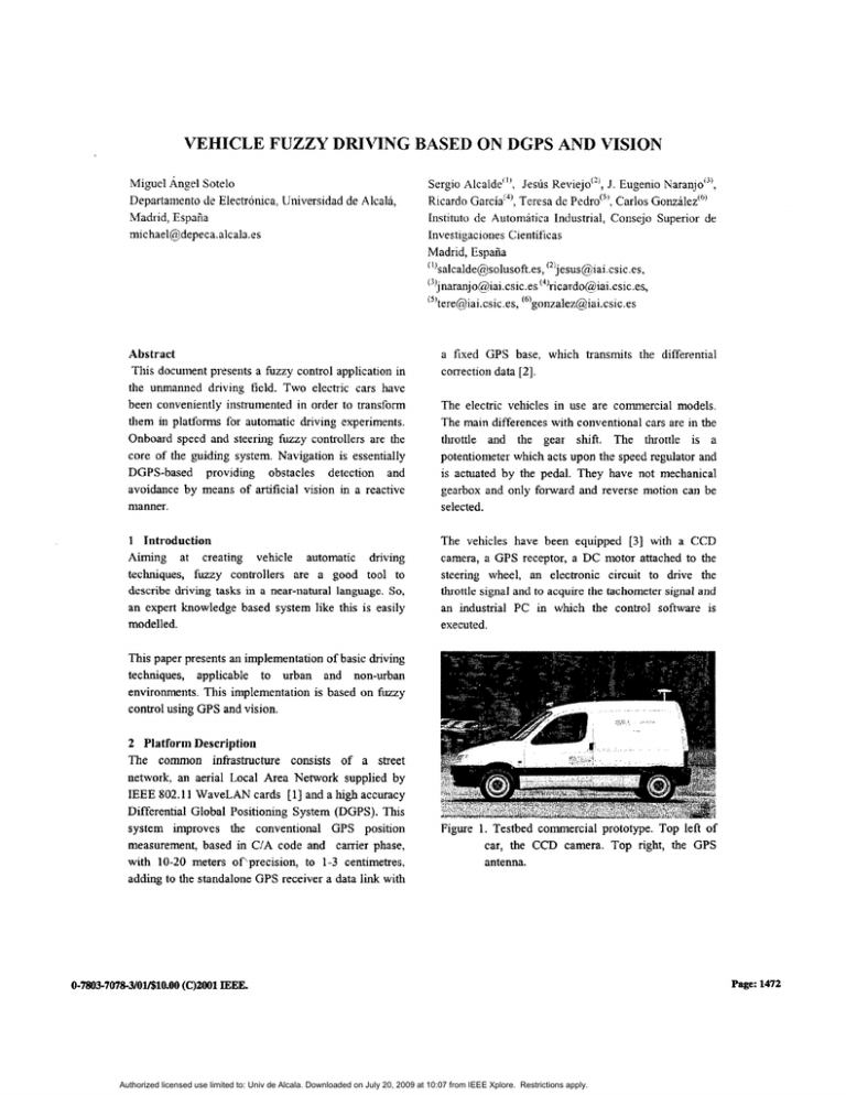
The vehicles have been equipped [3] with a CCD
camera, a GPS receptor, a DC motor attached to the
steering wheel, an electronic circuit to drive the
throttle signal and to acqulre the lachorncler signal and
an industrial PC in which the control software is
executed.
a fixed GPS base. which transmits the differential
correction data 121.
This paper presents an implementation of basic driving
techniques, applicable to urban and non-urban
environments. This implementation is based on fuzzy
control using GPS and vision.
2 Platform Description
The common infrastructure consists of a street
network. an aerial Local Area Network supplied by
IEEE 802.11 WaveLAN car& [11 and a high accuracy
Differential Global Positioning System (DGPS). This
system improves the conventional GPS position
measurement, based in C/A code and carrier phase,
with 10-20 meters ofiprecision, to 1-3 centimetres.
adding to the standalone GPS receiver a data link with
Figure 1. Testbed commercial prototype. Top left of
car, the CCD camera. Top right, the GPS
antenna.
0-7803-7078-3/0U$l0.00
(C)U)ol IEEE.
Authorized licensed use limited to: Univ de Alcala. Downloaded on July 20, 2009 at 10:07 from IEEE Xplore. Restrictions apply.
Page: 1472
3 Logical Description
The representation of a circuit in order to perform the
automatic dnving is a concatenation of reference
straight segments, represented by the North and East
UTM coordinates of its extremes, previously obtained
from the DGPS. The tracking of each segment and
transition among them is done by means of the
actuation upon the steering wheel, which is performed
by a fuzzy controller [4][5]. This is accomplished by
taking as inputs the orientation angle and the lateral
error (in the rules, yaw and drift, respectively for
short) between the car and the reference segment. The
input data are computed fiom the positions acquired
by the DGPS. Besides, a speed fuzzy controller has
been implemented too. This controller provides an
increment on the position of the throttle, taking as
inputs the speed error and the acceleration [6].
3.1 Speed Fuzzy Controller
The aim of the speed fuzzy controller is to guarantee
the car moves at the desired speed. The inputs are the
speed error and the acceleration. The output is a
change in the voltage of the throttle signal (an
increment in this voltage is equivalent to increase the
pressure on the throttle and a decrement is similar to
decrease it). There are four rules which govern this
behaviour (Table 1). The fuzzy strategies description
language pennits the utilisation of modifiers in
expressions like less than or greater than .
Table 1. Speed fuzzy controller rules
Iif speed-error is less than zero
then throttle down
if speed-error is greater than zero
then throttle up
if acceleration is greater than zero
then throttle up
if acceleration is less than zero
then throttle down
Speed-error = real-speed - desired-speed
I
3.2 Steering Fuzzy Controller
The steering fuzzy controller is in charge of tracking
each reference segment as well as each transition
between them. To achieve this, two sets of basic
behaviours have been defined by means of two
different fuzzy contexts, which are needed in order to
emulate human driving: usually, in straight line
driving, the vehicle speed is high and thus the steering
wheel must be turned slightly and smoothly. However,
in closed curves,-the car speed is low and thus the
driver moves the steering wheel widely and rapidly.
The defined fuzzy contexts match these two observed
driving modes and are applied to track the segments
and the transitions respectively. Though the rules for
both contexts are the same (Table 2), the membership
functions of the linguistic values are different.
Table 2. Steering fuzzy controller Id e s
if yaw is left
then steering right
if yaw is right
then steering left
if drift is right
then steering left
if drift is left
then steering right
3 3 Obstacle Detection and Avoidance
The main goal is to provide obstacle detection using
computer vision. Additional inputs and rules must be
added to both the speed and steering fuzzy controllers
in order to account for obstacles.
The incoming image is on hardware re-scaled,
building a low resolution image of what can be called
the Area of Interest (AOI), comprising a squared area.
3.3.1 Road Estimation
Previous research groups [7] have widely
demonstrated that the reconstruction of road geometry
can be simplified by assumptions on its shape. Thus,
we use a polynomial representation assuming that the
road edges can be modelled as parabolas [8] in the
image plane. Similarly, the assumption of smoothly
varying lane width allows the enhancement of the
search criterion, limiting the search to almost parallel
edges. On the other hand, due to both physical and
continuity constraints, the processing of the whole
image is replaced by the analysis of a specific region
of interest in which the relevant features are more
likely to be found. This is a generally followed
0-7803-7078-3/Oll$lO.W(C)U#)lIEEE.
Authorized licensed use limited to: Univ de Alcala. Downloaded on July 20, 2009 at 10:07 from IEEE Xplore. Restrictions apply.
Page: 1473
strategy [9] that can be adopted assuming a priori
knowledge on the road environment. All these well
known assumptions enhance and speed-up the road
estimation processing [lo].
The incoming image is on hardware re-scaled,
building a low resolution image of what we call the
Area of Interest (AOI), comprising the nearest 20 m
ahead of the vehicle. The A01 is segmented basing on
colour properties and shape restrictions. The proposed
segmentation relies on the HSI (hue, saturation,
intensity) colour space [ l l ] because of its close
relation to human perception of colours. The hue
component represents the impression related to the
dominant wavelength of the colour stimulus. The
saturation corresponds to relative colour purity, and so,
colours with no saturation are grey-scale colours.
Intensity is the amount of light in a colour. In contrast,
the RGB colour space has a high correlation between
its components( R-B, R-G, G-B). In terms of
segmentation, the RGB colour space is usually not
preferred because it is psychologically non-intuitive
and non-uniform, The scheme performs in two steps:
Pixels are classified as chromatic or achromatic as a
function of their HSI colour values: hue is meaningless
when the intensity is extremely high or extremely low.
On the other hand, hue is unstable when the saturation
is very low. According to this, achromatic pixels are
those complying with the conditions specified in
equation 1.
where the saturation S and the intensity I values are
normalised from 0 to 100.
Pixels are classified into road and non-road (including
obstacles). Chromatic pixels are segmented using their
HSI components: each pixel in the low resolution
image is compared to a set of pattem pixels obtained
in the first image in a supervised manner. The distance
measure used for comparing pixel colours is a
cylindrical metric. It computes the distance between
the projections of the pixel points on a chromatic
plane, as defined in equation 2.
d,, =J(S,)’
+ ( S i ) ’ + 2 S , S i cos0
where
Subscript i stands for the pixel under consideration,
while subscript s represents the pattem value. An
examination of the metric equation shows that it can
be considered as a form of the popular Euclidean
distance (L2 norm) metric. A pixel is assigned to the
road region if the value of the metric dcYl~dricalis lower
than a threshold T b m . To account for shape
restrictions, the threshold Tho, is affected by an
exponentially decay factor yielding the new threshold
value r that depends on the distance from the current
pixel to the previously estimated road model, denoted
by d as defined in equation 6.
w
where
stands for the estimated width of the road
and K is an empirically set parameter. This makes
regions closest to the previous model be more likely to
be segmented as road.
For achromatic pixels, intensity is the only justified
colour attribute that can be used when comparing
pixels. A simple linear distance is applied in this case,
so that the pixel is assigned to the road region if the
difference is lower than a threshold value Tach,,,,
similarly affected by an exponential factor, as equation
7 shows.
0-7803-7078-3/0V$l0.00
(C)u)Ol IEEE.
Authorized licensed use limited to: Univ de Alcala. Downloaded on July 20, 2009 at 10:07 from IEEE Xplore. Restrictions apply.
Page: 1474
(7 I
Once the segmentation is accomplished, a time-spatial
filtcr removes non consistent objects in the low
resolution image, both in space and t h e (sporadic
noise), After that. the maximum horizontal clearance
(absence of non-road sections) is determined for each
line in the A01. The measured points are fed into a
Least Squares Filter with Exponential Decay that
computes the road edges in the image plane, using a
second order (parabolic) polyiornial. Using the road
shape and an estimation of' the road width (basing on
the previous segmentation) the exact area of the image
where the obstacles are expected to appear can be
calculated. Obviously, obstacles are searched for only
within the estimated area in the previous iteration.
Inlage I depicts an example of lane tracking in which
both the road edges and the centxe of the road have
been highlighted.
4.1 Speed Fuzzy Controller Results
The obtained results show an erroT less than 0.5 km'h
when a constant speed is tried to be maintained (Figure
3).
25
20
-f
15
ii.
T)
j
i
\
16
5
Figure 3. Speed controller behaviour example: step
response at several speeds.
4.2 Steering Fuzzy Controller Results
The system is able to track straight segments at speeds
up to 65 Kmh, which i s the maximum s p e d the car
can reach in the longcst street (about 250 meters).
Furthermore, straight angle and more closed curves,
like a circle to turn around, are tracked at speeds less
than 6 Kndh (Figure 4).
#
458.8
458.85
4589
45895
459
I___._ L.......;
459.05
East (Km)
Figure 2. Lane tracking example
4 Experiments and Results
Next, the behaviour of the dfferent subsystems is
shown separately.
Figure 4. An steering control example: tracking of a
circuit with several straight segments and
curves (axes units expressed in UTM
coordinates).
4.3 Obstacle Detection Results
Obstacles in front of the vehicle, such as cars, are
detected with enough resolution within a safety
distance of loin ahead of the vehicle, processing up to
0-7803-7@78-3/0l/$10.00(C)zoOl IEEE.
Authorized licensed use limited to: Univ de Alcala. Downloaded on July 20, 2009 at 10:07 from IEEE Xplore. Restrictions apply.
Page: 1475
15 framesis. Figure 2 shows a series of images
covermg a stretch of road where another vehicle
appears in the opposite lane. The obstacle and lane
positions are determined, as illustrstcd in the figure, so
as to modify the fiizzy controller inputs hozh for angle
and velocity to issue obstacles detection capacity.
4.4 Obstacle Avoidance Results
Obstacles detected along the vehicle path can bc
avoided by the fuzzy controller whenever the vision
system determines thcrc is enough space for the robot
to perform the avoidance manoeuvring. It starts
decreasing speed and modifying the tuming response
until the obstacle is surroundcd. After that, nonnal
tracking is resumed. In case that not enough space is
detected, the vehicle stops.
6 Acknowledgements
This work has been founded by the projects: COVAN
C.4M 06T/042/96; ORBEX CICYT TIC 9611393.~0603, ZOCO CICYT I1\: 96-01 18: GLOB0 CICYI ‘YAP
98-0513.
7 References
J.E. Karanjo, J. Reviejo, and C. Gonzilez,
“Sistema distribuido de conduccion automitica
usando control borroso”, SET11 2000,
September 2000, pp 107-1 15.
RTCM Special Committee no. 104, RTCM
Recommended Standards f o r Differenlid
Navstar GPS Sewice, Radio Technical
Commission for Maritime Services, USA 1994.
S. Alcalde. ItistmmentuciLin de un vehiculo
electrico paru una conriirccion autombtica. End
of grade project, Escuela IJniversitaria de
Infodtica, Universidad Politkcnica de
Madrid, Madrid. Spain, January 2000.
R. Garcia, and T. de Pedro. “Modeling a Fuzzy
Coprocessor and its Programming Language”,
Mathware and Soft Computing, V, 1998, pp
167-174.
M.
Sugeno, and Murofoshi, “Fuzzy
Algorithmic Control of Model Car by Oral
Instructions”, 2”* IFSA Congress, Tokyo, 1991.
Figure 5. Obstacle and lane determination.
5 Conclusions
An autonomous navigation system based on
cooperation between DGPS and vision has been
designed and implemented on a commercial vehicle
for unmanned transport applications. The technology
techniques developed in this work can also be applied
to provide assisted driving. Current tests are being
carried out to enhance performance robustness.
The real application of theoretical and simulated fizzy
controllers is the main novelty of this vehicle driving
system. This is not linlited to platoon or highway
tracking but it is a emulation of the human car driving
applicable to any road circumstances like highway,
platoons [121, city driving, overtaking [ 131. parking,
etc. This system is adaptable to any circumstances if
needed.
J. Reviejo, T. de Pedro, J.E. Waranjo, K. Garcia,
C. Gonzalez, and S. Alcalde, ”An Open Frame
to Test Techniques and Equipment for
Autonomous Vehicles”, IFAC Symposium on
Manufacturing, Modeling, Management and
Control (MIM ZOOO), University of Patras, Rio,
Greece, July 2000, pp 350-354.
M. IAtzeler, and E.D. Dickmanns, “Road
Recognition with MarVEye”, Proceedings of
the IEEE Intelligent Vehicles Symposium ’98,
Stuttgart, Germany, October 1998, pp. 341-346.
S.L. Michael Beuvais, and C. Kreucher,
“Building world model for mobile platforms
using heterogeneous sensors fusion and
temporal analysis”, Proceedings of the IEEE
International Conference on Intelligent
Transportation Systems ‘97, Boston, MA,
November 1997, p.101.
J. Goldbeck, D. Graeder, B. Huertgen, S. Emst,
and F. WiIms, “Lane following combining
vision and DGPS”, Proceedings of the IBEE
Intelligent Vehicles Symposium ’98, Stuttgart,
Germany, October 1998, pp. 445-450.
0-7803-7078-3/0V$l0.00
(C)2001IEEE.
Authorized licensed use limited to: Univ de Alcala. Downloaded on July 20, 2009 at 10:07 from IEEE Xplore. Restrictions apply.
Page: 1476
[lo]
M. Bertozzi, A. Broggi, and A. Fascioli,
“Vision-based intelligent vehicles: State of the
art and perspectives”, Robotics and
Autonomous Systems, 32,2000, pp. 1-16.
[ 111 N. Ikonomakis, K.N. Plataniotis, A.N.
Venetsanopoulos, “Colour Image Segmentation
for Multimedia Applications”, Journal of
Intelligent and Robotics Systems 28, 2000
Kluwer Academic Publishers, pp. 5-20.
[12]
Mun, Dickerso, Kosko, “Fuzzy throttle and
brake control for platoon of smart cars”, Fuzzy
Sets and Systems, 84, 1996, pp. 209-234.
[13]
S. Huang, W. Ren,“Use of neural fuzzy
networks
with
mixed
genetidgradient
algorithm in automatic vehicle control”, IEE
Transactions on Industrial Electronics,46, 1999,
pp. 1090-1 102.
0-7803-7078-3/0l/$l0~00
(C)U#)l IEEE.
Authorized licensed use limited to: Univ de Alcala. Downloaded on July 20, 2009 at 10:07 from IEEE Xplore. Restrictions apply.
Page: 1477
