instrucciones _610_50
Anuncio
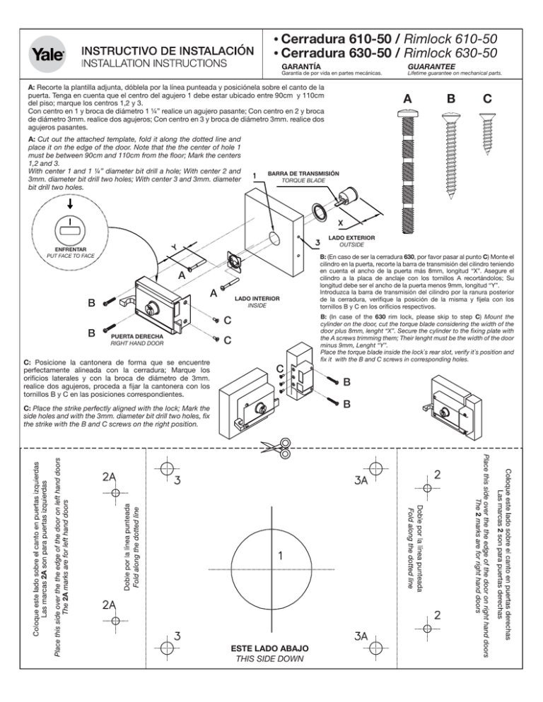
Cerradura 610-50 / Rimlock 610-50 Cerradura 630-50 / Rimlock 630-50 GARANTÍA Garantía de por vida en partes mecánicas. A: Recorte la plantilla adjunta, dóblela por la línea punteada y posiciónela sobre el canto de la puerta. Tenga en cuenta que el centro del agujero 1 debe estar ubicado entre 90cm y 110cm del piso; marque los centros 1,2 y 3. Con centro en 1 y broca de diámetro 1 ¼” realice un agujero pasante; Con centro en 2 y broca de diámetro 3mm. realice dos agujeros; Con centro en 3 y broca de diámetro 3mm. realice dos agujeros pasantes. A: Cut out the attached template, fold it along the dotted line and place it on the edge of the door. Note that the the center of hole 1 must be between 90cm and 110cm from the floor; Mark the centers 1,2 and 3. With center 1 and 1 ¼” diameter bit drill a hole; With center 2 and 3mm. diameter bit drill two holes; With center 3 and 3mm. diameter bit drill two holes. A B C BARRA DE TRANSMISIÓN TORQUE BLADE LADO EXTERIOR OUTSIDE ENFRENTAR PUT FACE TO FACE A A B B GUARANTEE Lifetime guarantee on mechanical parts. LADO INTERIOR INSIDE C PUERTA DERECHA RIGHT HAND DOOR C: Posicione la cantonera de forma que se encuentre perfectamente alineada con la cerradura; Marque los orificios laterales y con la broca de diámetro de 3mm. realice dos agujeros, proceda a fijar la cantonera con los tornillos B y C en las posiciones correspondientes. C C B: (En caso de ser la cerradura 630, por favor pasar al punto C) Monte el cilindro en la puerta, recorte la barra de transmisión del cilindro teniendo en cuenta el ancho de la puerta más 8mm, longitud “X”. Asegure el cilindro a la placa de anclaje con los tornillos A recortándolos; Su longitud debe ser el ancho de la puerta menos 9mm, longitud “Y”. Introduzca la barra de transmisión del cilindro por la ranura posterior de la cerradura, verifique la posición de la misma y fíjela con los tornillos B y C en los orificios respectivos. B: (In case of the 630 rim lock, please skip to step C) Mount the cylinder on the door, cut the torque blade considering the width of the door plus 8mm, lenght “X”. Secure the cylinder to the fixing plate with the A screws trimming them; Their lenght must be the width of the door minus 9mm, Lenght “Y”. Place the torque blade inside the lock`s rear slot, verify it`s position and fix it with the B and C screws in corresponding holes. B B C: Place the strike perfectly aligned with the lock; Mark the side holes and with the 3mm. diameter bit drill two holes, fix the strike with the B and C screws on the right position. ESTE LADO ABAJO THIS SIDE DOWN
