cathedral ceiling fan canopy kit
Anuncio
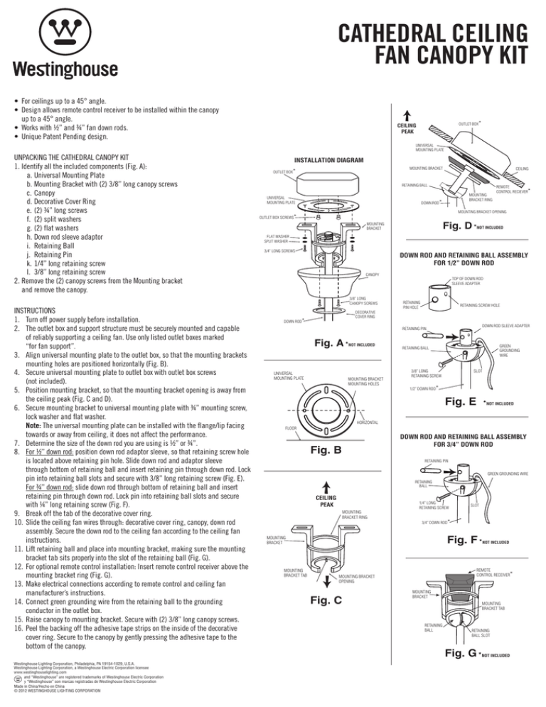
CATHEDRAL CEILING FAN CANOPY KIT • For ceilings up to a 45° angle. • Design allows remote control receiver to be installed within the canopy up to a 45° angle. • Works with ½” and ¾” fan down rods. • Unique Patent Pending design. OUTLET BOX* CEILING PEAK UNIVERSAL MOUNTING PLATE UNPACKING THE CATHEDRAL CANOPY KIT 1. Identify all the included components (Fig. A): a. Universal Mounting Plate b. Mounting Bracket with (2) 3/8” long canopy screws c. Canopy d. Decorative Cover Ring e. (2) ¾” long screws f. (2) split washers g. (2) flat washers h. Down rod sleeve adaptor i. Retaining Ball j. Retaining Pin k. 1/4” long retaining screw l. 3/8” long retaining screw 2. Remove the (2) canopy screws from the Mounting bracket and remove the canopy. INSTALLATION DIAGRAM MOUNTING BRACKET OUTLET BOX* RETAINING BALL UNIVERSAL MOUNTING PLATE MOUNTING BRACKET RING DOWN ROD* REMOTE CONTROL RECIEVER* MOUNTING BRACKET OPENING OUTLET BOX SCREWS* Fig. D * MOUNTING BRACKET NOT INCLUDED FLAT WASHER SPLIT WASHER 3/4” LONG SCREWS DOWN ROD AND RETAINING BALL ASSEMBLY FOR 1/2” DOWN ROD CANOPY 3/8” LONG CANOPY SCREWS INSTRUCTIONS 1. Turn off power supply before installation. 2. The outlet box and support structure must be securely mounted and capable of reliably supporting a ceiling fan. Use only listed outlet boxes marked “for fan support”. 3. Align universal mounting plate to the outlet box, so that the mounting brackets mounting holes are positioned horizontally (Fig. B). 4. Secure universal mounting plate to outlet box with outlet box screws (not included). 5. Position mounting bracket, so that the mounting bracket opening is away from the ceiling peak (Fig. C and D). 6. Secure mounting bracket to universal mounting plate with ¾” mounting screw, lock washer and flat washer. Note: The universal mounting plate can be installed with the flange/lip facing towards or away from ceiling, it does not affect the performance. 7. Determine the size of the down rod you are using is ½” or ¾”. 8. For ½” down rod: position down rod adaptor sleeve, so that retaining screw hole is located above retaining pin hole. Slide down rod and adaptor sleeve through bottom of retaining ball and insert retaining pin through down rod. Lock pin into retaining ball slots and secure with 3/8” long retaining screw (Fig. E). For ¾” down rod: slide down rod through bottom of retaining ball and insert retaining pin through down rod. Lock pin into retaining ball slots and secure with ¼” long retaining screw (Fig. F). 9. Break off the tab of the decorative cover ring. 10. Slide the ceiling fan wires through: decorative cover ring, canopy, down rod assembly. Secure the down rod to the ceiling fan according to the ceiling fan instructions. 11. Lift retaining ball and place into mounting bracket, making sure the mounting bracket tab sits properly into the slot of the retaining ball (Fig. G). 12. For optional remote control installation: Insert remote control receiver above the mounting bracket ring (Fig. G). 13. Make electrical connections according to remote control and ceiling fan manufacturer’s instructions. 14. Connect green grounding wire from the retaining ball to the grounding conductor in the outlet box. 15. Raise canopy to mounting bracket. Secure with (2) 3/8” long canopy screws. 16. Peel the backing off the adhesive tape strips on the inside of the decorative cover ring. Secure to the canopy by gently pressing the adhesive tape to the bottom of the canopy. CEILING TOP OF DOWN ROD SLEEVE ADAPTER RETAINING PIN HOLE RETAINING SCREW HOLE DECORATIVE COVER RING DOWN ROD* DOWN ROD SLEEVE ADAPTER RETAINING PIN Fig. A * UNIVERSAL MOUNTING PLATE NOT INCLUDED MOUNTING BRACKET MOUNTING HOLES GREEN GROUNDING WIRE RETAINING BALL 3/8” LONG RETAINING SCREW SLOT 1/2” DOWN ROD* Fig. E *NOT INCLUDED HORIZONTAL FLOOR DOWN ROD AND RETAINING BALL ASSEMBLY FOR 3/4” DOWN ROD Fig. B RETAINING PIN GREEN GROUNDING WIRE RETAINING BALL CEILING PEAK MOUNTING BRACKET RING 1/4” LONG RETAINING SCREW 3/4” DOWN ROD* Fig. F * MOUNTING BRACKET MOUNTING BRACKET TAB SLOT REMOTE CONTROL RECEIVER* MOUNTING BRACKET OPENING Fig. C NOT INCLUDED MOUNTING BRACKET MOUNTING BRACKET TAB RETAINING BALL RETAINING BALL SLOT Fig. G * NOT INCLUDED Westinghouse Lighting Corporation, Philadelphia, PA 19154-1029, U.S.A. Westinghouse Lighting Corporation, a Westinghouse Electric Corporation licensee www.westinghouselighting.com and “Westinghouse” are registered trademarks of Westinghouse Electric Corporation y “Westinghouse” son marcas registradas de Westinghouse Electric Corporation Made in China/Hecho en China © 2012 WESTINGHOUSE LIGHTING CORPORATION JUEGO DE DOSEL PARA VENTILADOR DE TECHO ESTILO CATEDRAL • Para cielos rasos que requieren un ángulo de hasta 45˚ • El diseño permite la instalación del receptor del control remoto dentro del dosel en un ángulo de hasta 45°. • Funciona con varillas verticales de ventilador de 1.27 y 1.91 cm (½” y ¾ pulg.) • Diseño exclusivo con patente en trámite. EXTRAIGA EL JUEGO DE DOSEL ESTILO CATEDRAL: 1. Identifique todos los componentes incluidos (Fig. A): a. Placa de montaje universal b. Soporte de montaje con (2) tornillos para dosel de 0.95 cm (3/8 pulg.) de longitud c. Dosel d. Anillo decorativo e. (2) tornillos largos de 1.91 cm (¾ pulg.) f. (2) arandelas grower g. (2) arandelas planas h. Adaptador para cubierta de varilla vertical i. Bola de sujeción j. Pasador de sujeción k. Tornillo de sujeción de 0.64 cm (¼ pulg.) de longitud l. Tornillo de sujeción de 0.95 cm (3/8 pulg.) de longitud 2. Quite los (2) tornillos del dosel del soporte de montaje y extraiga el dosel. CAJA DE EMBUTIR* CÚSPIDE DEL TECHO BARRA DE MONTAJE UNIVERSAL DIAGRAMA DE INSTALACIÓN SOPORTE DE MONTAJE CAJA DE EMBUTIR* CIELO RASO BOLA DE SUJECIÓN BARRA DE MONTAJE UNIVERSAL RECEPTOR DEL CONTROL REMOTO* ANILLO DEL SOPORTE DE MONTAJE VARILLA VERTICAL* ORIFICIO DEL SOPORTE DE MONTAJE TORNILLOS DE LA CAJA DE EMBUTIR* Fig. D * SOPORTE DE MONTAJE NO INCLUIDO ARANDELA PLANA ARANDELA GROWER TORNILLOS DE 1.91 CM (3/4 PULG.) INSTRUCCIONES 1. Desconecte el suministro eléctrico antes de la instalación. 2. La caja de embutir y la estructura de apoyo deben estar montadas de forma segura y poder soportar de forma confiable un ventilador de techo. Use solo en una caja de embutir rotulada como “adecuada para ventilador”. 3. Alinee la placa de montaje universal a la caja de embutir, de modo que los orificios de montaje de los soportes de montaje estén ubicados de forma horizontal (Fig. B). 4. Fije la placa de montaje universal a la caja de embutir con los tornillos de la caja de embutir (no incluidos). 5. Posicione el soporte de montaje de modo que el orificio del soporte de montaje quede lejos de la cúspide del techo (Fig. C y D). 6. Fije el soporte de montaje a la placa de montaje universal usando el tornillo de montaje de 1.91 cm (¾ pulg.), la arandela de presión y la arandela plana. Nota: La placa de montaje universal puede ser instalada con la pestaña/el borde orientada/o hacia abajo o hacia el cielorraso, lo que no afecta su desempeño. 7. Determine si el tamaño de la varilla vertical que está usando es de 1.27 o 1.90 cm (½ o ¾ pulg.). 8. Para una varilla de 1.27 cm (1/2 pulg.): Posicione el adaptador para cubierta de varilla vertical, de modo que el orificio del tornillo de sujeción quede ubicado sobre el orificio del pasador de sujeción (Fig. E). Deslice la varilla vertical y el adaptador a través de la parte inferior de la bola de sujeción e introduzca el pasador de sujeción a través de la varilla vertical. Fije el pasador por las ranuras de la bola de sujeción y asegure con el tornillo de sujeción de 0.95 cm (3/8 pulg.) de longitud (Fig. F). Para una varilla de 1.91 cm (3/4 pulg.): deslice la varilla vertical a través de la parte inferior de la bola de sujeción e introduzca el pasador de sujeción a través de la varilla vertical. Fije el pasador por las ranuras de la bola de sujeción y asegure con el tornillo de sujeción de 0.63 cm (1/4 pulg.) de longitud (Fig. F). 9. Corte la lengüeta del anillo decorativo. 10. Pase los cables del ventilador de techo a través del: anillo decorativo, dosel y conjunto de la varilla vertical. Asegure la varilla vertical al ventilador de techo siguiendo las instrucciones del ventilador de techo. 11. Levante la bola de sujeción y colóquela dentro del soporte de montaje, asegúrese de que las lengüetas del soporte de montaje calcen adecuadamente en la ranura de la bola de sujeción (Fig. G). 12. Instrucciones para la instalación óptima del control remoto: introduzca el receptor del control remoto encima del anillo del soporte de montaje (Fig. G). 13. Haga las conexiones eléctricas siguiendo las indicaciones del fabricante del control remoto y ventilador de techo. 14. Conecte el cable verde de tierra de la bola de sujeción al conductor de tierra de la caja de embutir. 15. Levante el dosel hacia el soporte de montaje. Asegure con (2) tornillos para dosel de 0.95 cm (3/8 pulg.) de longitud. 16. Quite la parte posterior de las tiras de cinta adhesiva del interior del anillo de la cubierta decorativa. Fíjelo al dosel presionando levemente la cinta adhesiva contra la parte inferior del dosel. DOSEL CONJUNTO DE VARILLA VERTICAL Y BOLA DE SUJECIÓN PARA VARILLA DE 1.27 CM (1/2 PULG.) PARTE SUPERIOR DEL ADAPTADOR PARA CUBIERTA DE VARILLA VERTICAL TORNILLOS PARA DOSEL DE 0.95 CM 3/8 PULG.) DE LONGITUD ANILLO DECORATIVO VARILLA VERTICAL* ORIFICIO PARA TORNILLO DE SUJECIÓN ORIFICIO PARA PASADOR DE SUJECIÓN Fig. A * NO INCLUIDO ADAPTADOR PARA CUBIERTA DE VARILLA VERTICAL PASADOR DE SUJECIÓN CABLE VERDE DE TIERRA BOLA DE SUJECIÓN TORNILLO DE SUJECIÓN DE 0.95 CM (3/8 PULG.) DE LONGITUD PLACA DE MONTAJE UNIVERSAL MOUNTING HOLES ORIFICIOS DE MONTAJE VARILLA VERTICAL DE * 1.27 CM (1/2 PULG.) RANURA Fig. E *NO INCLUIDO HORIZONTAL PISO Fig. B CONJUNTO DE VARILLA VERTICAL Y BOLA DE SUJECIÓN PARA VARILLA DE 1.91 CM (3/4 PULG.) PASADOR DE SUJECIÓN CABLE VERDE DE TIERRA BOLA DE SUJECIÓN CÚSPIDE DEL TECHO ANILLO DEL SOPORTE DE MONTAJE TORNILLO DE SUJECIÓN DE 0.64 CM(1/4 PULG.) DE LONGITUD VARILLA VERTICAL DE* 1.91 CM (3/4 PULG.) RANURA Fig. F * SOPORTE DE MONTAJE LENGÜETA DEL SOPORTE DE MONTAJE RECEPTOR DEL CONTROL REMOTO* ORIFICIO DEL SOPORTE DE MONTAJE Fig. C NO INCLUIDO SOPORTE DE MONTAJE LENGÜETA DEL SOPORTE DE MONTAJE BOLA DE SUJECIÓN RANURA DE LA BOLA DE SUJECIÓN Fig. G * NO INCLUIDO Westinghouse Lighting Corporation, Philadelphia, PA 19154-1029, U.S.A. Westinghouse Lighting Corporation, a Westinghouse Electric Corporation licensee www.westinghouselighting.com and “Westinghouse” are registered trademarks of Westinghouse Electric Corporation y “Westinghouse” son marcas registradas de Westinghouse Electric Corporation Made in China/Hecho en China © 2012 WESTINGHOUSE LIGHTING CORPORATION
