Multiplexor de 4-a-1
Anuncio
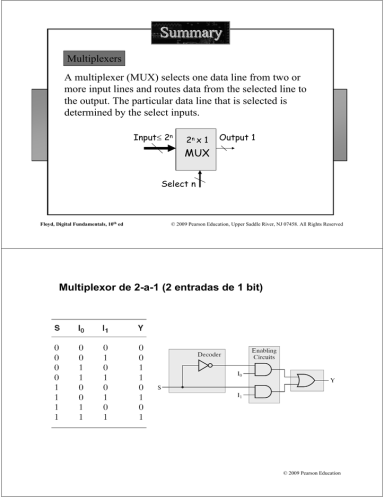
Summary Multiplexers A multiplexer (MUX) selects one data line from two or more input lines and routes data from the selected line to the output. The particular data line that is selected is determined by the select inputs. Input≤ 2n 2n x 1 Output 1 MUX Select n Floyd, Digital Fundamentals, 10th ed © 2009 Pearson Education, Upper Saddle River, NJ 07458. All Rights Reserved Multiplexor de 2-a-1 (2 entradas de 1 bit) © 2009 Pearson Education Multiplexor de 4-a-1 (4 entradas de 1 bits) Two select lines are shown here to choose any of the four data inputs. Data Select Inputs S1 S0 0 0 1 1 0 1 0 1 Input Selected Y D0 D1 D2 D3 © 2009 Pearson Education Diagrama lógico del multiplexor de 4-a-1 Floyd, Digital Fundamentals, 10th ed © 2009 Pearson Education, Upper Saddle River, NJ 07458. All Rights Reserved Otra visión © 2009 Pearson Education 74HC157: Cuádruple multiplexor de 2-a-1 (multiplexor de 2 entradas de 4 bits) Floyd, Digital Fundamentals, 10th ed © 2009 Pearson Education, Upper Saddle River, NJ 07458. All Rights Reserved Floyd, Digital Fundamentals, 10th ed © 2009 Pearson Education, Upper Saddle River, NJ 07458. All Rights Reserved 74x157: otra descripción Floyd, Digital Fundamentals, 10th ed © 2009 Pearson Education, Upper Saddle River, NJ 07458. All Rights Reserved Multiplexación de dígitos BCD para un display 7-segmentos Floyd, Digital Fundamentals, 10th ed © 2009 Pearson Education, Upper Saddle River, NJ 07458. All Rights Reserved 74x153: Multiplexor de 4 entradas de 2 bits (doble multiplexor de 4-a-1) Floyd, Digital Fundamentals, 10th ed © 2009 Pearson Education, Upper Saddle River, NJ 07458. All Rights Reserved 74LS151: Multiplexor de 8-a-1 con habilitación bajo-activa Floyd, Digital Fundamentals, 10th ed © 2009 Pearson Education, Upper Saddle River, NJ 07458. All Rights Reserved De otra forma © 2009 Pearson Education Diagrama lógico © 2009 Pearson Education Aplicación: multiplexar 16 entradas de datos Floyd, Digital Fundamentals, 10th ed © 2009 Pearson Education, Upper Saddle River, NJ 07458. All Rights Reserved Expansión de multiplexores: multiplexor de 32-a-1 © 2009 Pearson Education Multiplexor de 64-a-1 © 2009 Pearson Education Cuádruple multiplexor de 4-a-1 (de 4 entradas de 4 bits) © 2009 Pearson Education Generador de funciones lógicas en forma de suma de productos Función de 3 variables con un mux 3-a-1 Inputs A2 A1 A0 0 0 0 0 0 1 0 1 0 0 1 1 1 0 0 1 0 1 1 1 0 1 1 1 Output Y 0 1 0 1 0 1 1 0 Floyd, Digital Fundamentals, 10th ed © 2009 Pearson Education, Upper Saddle River, NJ 07458. All Rights Reserved Para una función de 4 variables A0 A1 A2 A3 Floyd, Digital Fundamentals, 10th ed © 2009 Pearson Education, Upper Saddle River, NJ 07458. All Rights Reserved Dos realizaciones de un sumador completo © 2009 Pearson Education Summary Demultiplexers A demultiplexer (DEMUX) performs the opposite function from a MUX. It switches data from one input line to two or more data lines depending on the select inputs. Input 1 1 x 2n Output≤ 2n DEMUX Select n Floyd, Digital Fundamentals, 10th ed © 2009 Pearson Education, Upper Saddle River, NJ 07458. All Rights Reserved Un decodificador utilizado como demultiplexor (de 1-a-16) The 74LS138 was introduced previously as a decoder but can also serve as a DEMUX. When connected as a DEMUX, data is applied to one of the enable inputs, and routed to the selected output line depending on the select variables. Note that the outputs are active-LOW as illustrated in the following example… DEMUX Select lines Data input A0 A1 A2 G1 G2A G2B Y0 Y1 Y2 Y3 Y4 Y5 Y6 Y7 Data outputs 74LS138 © 2009 Pearson Education Summary Demultiplexers Determine the outputs, given the inputs shown. The output logic is opposite to the input because of the active-LOW convention. (Red shows the selected line). DEMUX A0 A1 A2 Data select lines Enable inputs G1 G2A G2B 74LS138 Floyd, Digital Fundamentals, 10th ed Y0 Y1 Y2 Y3 Y4 Y5 Y6 Y7 Data outputs A0 A1 A2 G1 G2A LOW G2B LOW Y0 Y1 Y2 Y3 Y4 Y5 Y6 Y7 © 2009 Pearson Education, Upper Saddle River, NJ 07458. All Rights Reserved El decodificador 74HC154 usado como demultiplexor (de 1-a-16) © 2009 Pearson Education Summary Parity Generators/Checkers Parity is an error detection method that uses an extra bit appended to a group of bits to force them to be either odd or even. In even parity, the total number of ones is even; in odd parity the total number of ones is odd. The ASCII letter S is 1010011. Show the parity bit for the letter S with odd and even parity. S with odd parity = 11010011 S with even parity = 01010011 Floyd, Digital Fundamentals, 10th ed © 2009 Pearson Education, Upper Saddle River, NJ 07458. All Rights Reserved Lógica básica de paridad © 2009 Pearson Education Summary Parity Generators/Checkers The 74LS280 can be used to generate a parity bit or to check an incoming data stream for even or odd parity. Checker: The 74LS280 can test codes with up to 9 bits. The even output will normally be HIGH if the data lines have even parity; otherwise it will be LOW. Likewise, the odd output will normally be HIGH if the data lines have odd parity; otherwise it will be LOW. Data inputs Generator: To generate even parity, the parity bit is taken from the odd parity output. To generate odd parity, the output is taken from the even parity output. Floyd, Digital Fundamentals, 10th ed (8) (9) (10) (11) (12) (13) (1) (2) (4) A B C D E (5) (6) F G H I Σ Even Σ Odd 74LS280 © 2009 Pearson Education, Upper Saddle River, NJ 07458. All Rights Reserved © 2009 Pearson Education
