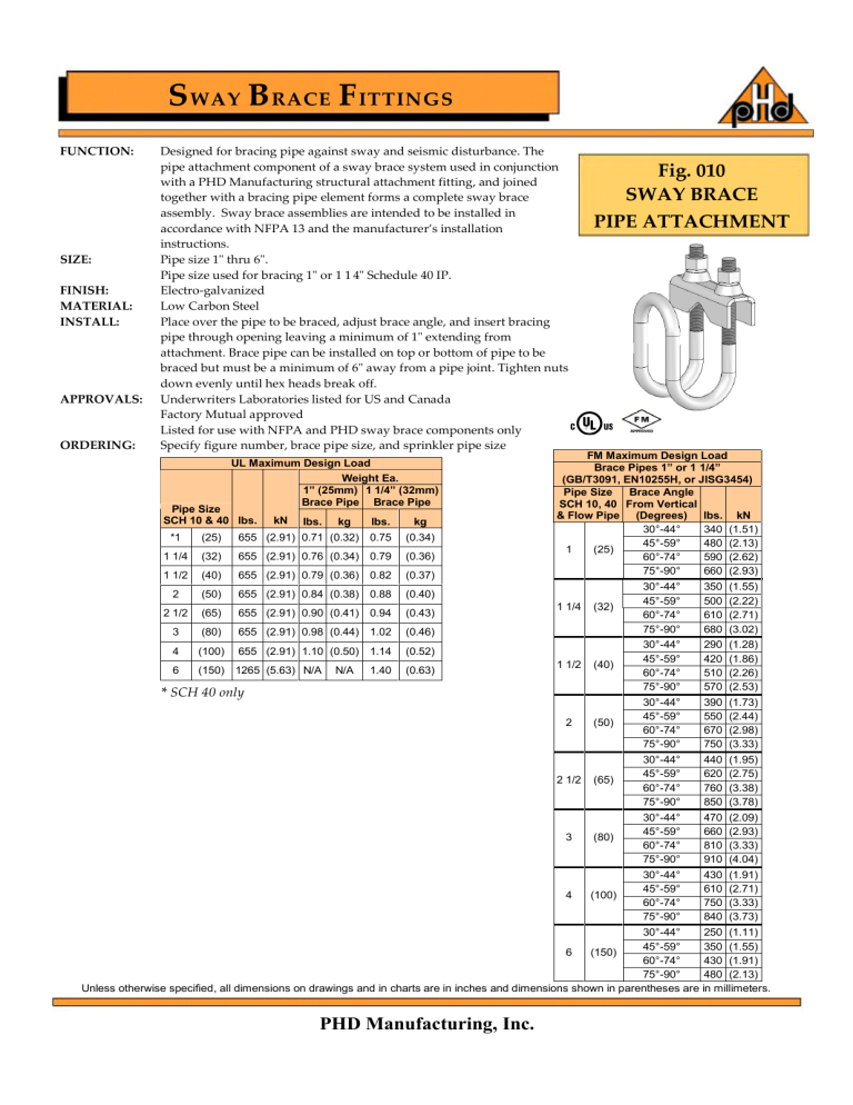
S WAY B RACE F ITTINGS FUNCTION: SIZE: FINISH: MATERIAL: INSTALL: APPROVALS: ORDERING: Designed for bracing pipe against sway and seismic disturbance. The pipe attachment component of a sway brace system used in conjunction with a PHD Manufacturing structural attachment fitting, and joined together with a bracing pipe element forms a complete sway brace assembly. Sway brace assemblies are intended to be installed in accordance with NFPA 13 and the manufacturer’s installation instructions. Pipe size 1" thru 6". Pipe size used for bracing 1" or 1 1/4" Schedule 40 IP. Electro-galvanized Low Carbon Steel Place over the pipe to be braced, adjust brace angle, and insert bracing pipe through opening leaving a minimum of 1" extending from attachment. Brace pipe can be installed on top or bottom of pipe to be braced but must be a minimum of 6" away from a pipe joint. Tighten nuts down evenly until hex heads break off. Underwriters Laboratories listed for US and Canada Factory Mutual approved Listed for use with NFPA and PHD sway brace components only Specify figure number, brace pipe size, and sprinkler pipe size UL Maximum Design Load Weight Ea. 1” (25mm) 1 1/4” (32mm) Brace Pipe Brace Pipe Pipe Size SCH 10 & 40 lbs. kN lbs. kg lbs. kg *1 (25) 655 (2.91) 0.71 (0.32) 0.75 (0.34) 1 1/4 (32) 655 (2.91) 0.76 (0.34) 0.79 (0.36) 1 1/2 (40) 655 (2.91) 0.79 (0.36) 0.82 (0.37) 2 (50) 655 (2.91) 0.84 (0.38) 0.88 (0.40) 2 1/2 (65) 655 (2.91) 0.90 (0.41) 0.94 (0.43) 3 (80) 655 (2.91) 0.98 (0.44) 1.02 (0.46) 4 (100) 655 (2.91) 1.10 (0.50) 1.14 (0.52) 6 (150) 1265 (5.63) N/A N/A 1.40 (0.63) Fig. 010 SWAY BRACE PIPE ATTACHMENT FM Maximum Design Load Brace Pipes 1” or 1 1/4” (GB/T3091, EN10255H, or JISG3454) Pipe Size Brace Angle SCH 10, 40 From Vertical & Flow Pipe (Degrees) lbs. kN 30°-44° 340 (1.51) 45°-59° 480 (2.13) 1 (25) 60°-74° 590 (2.62) 75°-90° 660 (2.93) 1 1/4 1 1/2 (32) 30°-44° 45°-59° 60°-74° 75°-90° 350 500 610 680 (1.55) (2.22) (2.71) (3.02) (40) 30°-44° 45°-59° 60°-74° 75°-90° 290 420 510 570 (1.28) (1.86) (2.26) (2.53) (50) 30°-44° 45°-59° 60°-74° 75°-90° 390 550 670 750 (1.73) (2.44) (2.98) (3.33) (65) 30°-44° 45°-59° 60°-74° 75°-90° 440 620 760 850 (1.95) (2.75) (3.38) (3.78) (80) 30°-44° 45°-59° 60°-74° 75°-90° 470 660 810 910 (2.09) (2.93) (3.33) (4.04) (100) 30°-44° 45°-59° 60°-74° 75°-90° 430 610 750 840 (1.91) (2.71) (3.33) (3.73) * SCH 40 only 2 2 1/2 3 4 30°-44° 250 (1.11) 45°-59° 350 (1.55) 6 (150) 60°-74° 430 (1.91) 75°-90° 480 (2.13) Unless otherwise specified, all dimensions on drawings and in charts are in inches and dimensions shown in parentheses are in millimeters. PHD Manufacturing, Inc.
