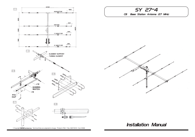
SY 27-4 1.1 CB Base Station Antenna (27 MHz) 1.2 2.0 3.0 3.1 4.0 Installation Manual B Copyright SIRIO antenne - Technical Data are subjected to change - Printed in ITALY - Rev. 09/07/2010 - Cod. ID099 DESCRIPTION MOUNTING INSTRUCTIONS 4 elements Yagi Beam antenna working on 27 MHz band with Gamma Match System. It has been completely made of anticorodal aluminium and supplied with big section Boom and steel bracket for the fitting on the support mast. The fixing part with rapid mounting system is made of die-cast metal to get the maximum strength. Every elements is supplied with jointing sleeves of polythene for a perfect water-proofing. Its supplied with UHF Female connector. 1.0 Assembling of elements Extract the telescopic elements unstringing the tube ∅ 12 and mount the jointing sleeve fixing the first section by means of the supplied phillips screw. Assemble the second jointing sleeve, string the top tube ∅ 8 together with its PVC cap and fix the end section by your phillips screw. SPECIFICATIONS Electrical Data Type Frequency Range Impedance Radiation Polarization Gain Bandwidth @ SWR ≤ 2 SWR @ res. freq. Max Power : : : : : : : : : Front to Back Ratio Connector : : Mechanical Data Materials Wind Load / Resistance Wind surface Dimensions (approx) Boom Length / Diameter Max. element lenght Element Diameter Turning Radius Weight (approx.) Mounting Mast : : : : : : : : : : 4 Elem. Yagi Beam Antenna 26.9-27.5 MHz @ SWR ≤ 2 50 Ω Directional Horizontal 11 dBd - 13.15 dBi ≥ 600 KHz (55 channel) ≤ 1.2 1000 Watts (CW) continuous, 3000 Watts (CW) short time 20 dB UHF Female Aluminium, Nylon, Steel 80 N at 150 Km/h / 120 Km/h 0.07 m2 5740 x 4030 x 100 mm 4030 mm / ∅ 33 mm 5740 mm ∅ 8-12-16 mm 3600 mm 6100 gr ∅ 35-50 mm HI-QUALITY ANTENNAS MADE IN ITALY ID099 1.1 Placing of elements on the Boom See the picture. 1.2 Assembling of elements to the Boom String the tuning element of Gamma Match on one element of the radator dipole, insert the elements into the metal support and fix them by using the screws and key supplied. 2.0 Assembling of Gamma Match Extract the final tube of Gamma Match to the length L1=365 mm and fix without locking the flat end ∅ 12 to the connector by using the supplied nut and washer. Move the tuning element towards the Boom stringing the end part ∅ 8 of Gamma Match as far as size L=675 mm. Then fix the tuning element by means of screw and key. Check once again the sizes L and L1, lock the nut on the flat part of Gamma Match and mount the PVC protection cap. 3.0 Assembling of bracket to the Boom See the picture. PLEASE, PAY ATTENTION. THE GREAT LOCKING TORQUE OF NUTS THAT FIX THE BOOM CAN CAUSE DAMAGE TO THIS LAST ONE. 3.1 Installation to the support tube See the picture. 4.0 Cable connection See the picture. 1.0
